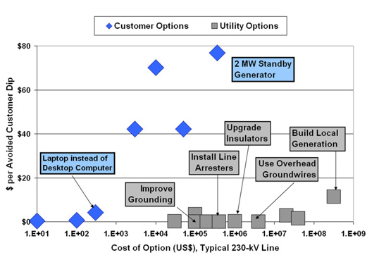
Transmission line surge arresters (TLSAs) have become an important design and mitigation alternative to improve grounding and reduce investment in overhead ground wire. However, they have also been known to experience a number of mechanical problems in service. Perhaps the most common of these is degradation of the components associated with flexible leads. Should a lead break away from a tower or the bottom of the arrester, its uncontrolled motion under wind can reduce electrical clearances. Moreover, some TLSAs have been installed in ways that negatively impact or even completely defeat the protection provided by Aeolian vibration dampers. This is of particular concern since current line design practice sees generally higher conductor tensions and therefore greater need for vibration control.
This edited contribution to INMR by Dr. William A. Chisholm and Dr. David G. Havard reviewed cases of interaction of TLSAs with vibration dampers as well as other line hardware such as aircraft marker balls, anti-galloping de-tuning pendulums, clamps on spacer dampers and post insulator struts. Vibration modes considered are: Aeolian type low amplitude high frequency vertical vibration that accumulates millions of stress cycles; and galloping, which is large amplitude low frequency oscillation. The later involves complex vertical, longitudinal and torsional motions that accumulate thousands of stress cycles, almost invariably with an ice layer on conductors. A third vibration mode: wake induced oscillation affects only bundled conductors and is not discussed.

Mounting Configurations
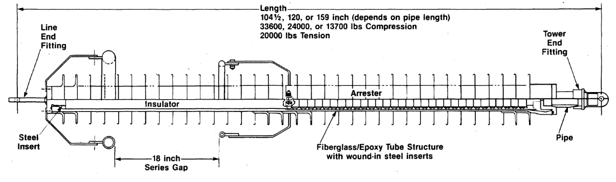
Perhaps the first recorded application of a metal-oxide type TLSA occurred in the early 1980s when a 138 kV line with single overhead ground wire was converted to a ‘compact’ construction by restraining the lateral motion of phase conductors. A hollow strut assembly provided an interior volume for the stack of cylindrical MOV blocks with diameters of 61 and 76 mm. The larger-diameter, heavier MOV elements were used on the top phases of the double circuit line to deal with the anticipated energy associated with shielding failures. Lightning strokes that bypass the OHGW transfer all their surge energy through a single arrester into the phase conductor and this arrester placement is called on to dissipate significantly higher levels of charge and energy.

The TLSAs in this case were attached directly to the conductor clamps (see Fig. 2). Since this design was rated for 89 kN (20,000 lb) tension and similar load in compression, it satisfied mechanical requirements for lateral restraint. At the same time, it did not interfere with function of the double sets of Aeolian vibration dampers. The 457 mm (18”) series ring gap provided electrical isolation from normal AC line voltage and switching surges and connected the MOV elements across the insulator only when lightning overvoltage exceeded 500 kV. As such, this was an early example of an externally gapped line arrester (EGLA) as now defined in IEC 60099 Part 8. This same type of arrester strut configuration could also be used in a braced post design provided that mechanical and electrical failure modes are coordinated. If the arrester base becomes pinned, its mass does not have much impact on tension equalization among spans. Moreover, it would also not affect line clearances and thermal ratings. Function of vibration dampers and other motion control devices are also not affected by this arrester configuration.
Arrester Suspended from Conductor
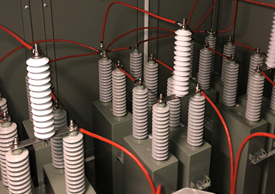
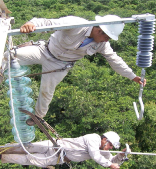
Provision of an external gap in the EGLA design calls for use of an insulating element that can withstand full line voltage for weeks or even years should the series varistor unit (SVU) component fail, e.g. by typical short circuit. A low-cost alternative for two insulating housings in series has been use of an external disconnecting device. On overload, e.g. at a charge level of 2 to 10 Coulomb, electrical energy heats and fires an explosive charge that separates either the lead connecting the arrester to the power line or the lead connecting the arrester to ground (see Fig. 3).
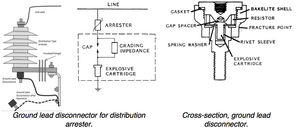
(left) Ground lead disconnector for distribution arrester; (right) cross-section, ground lead disconnector.
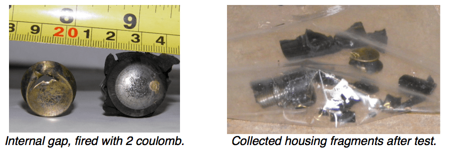
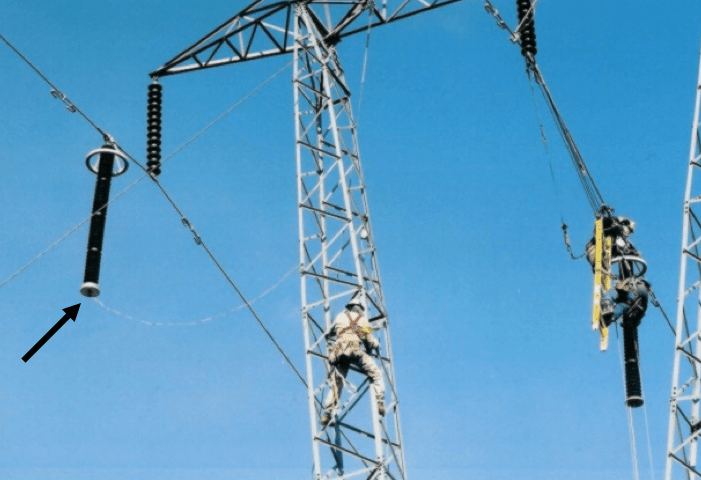
The modest weight of the arrester body is supported from below by an insulated hanger. If the ground lead disconnector operates, it shatters (as in Fig. 4) and the ground lead falls away. The base of the distribution arrester remains energized but the broken lead is a signal that it needs replacement.
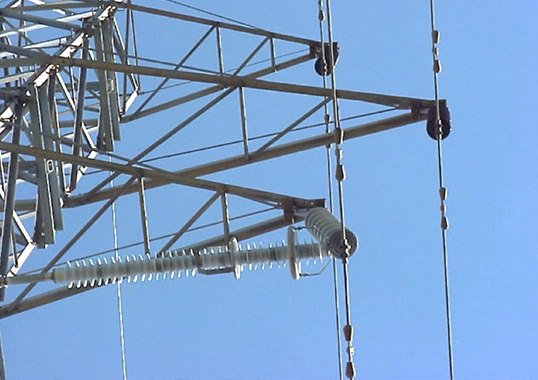
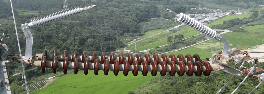
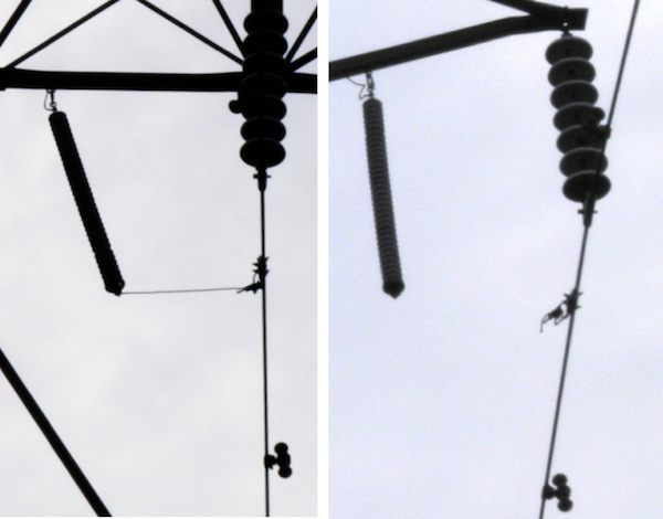
By 2001, polymer housed TLSA technology using explosive disconnects in the ground lead had scaled from distribution systems up to ratings of 180 kV and 195 kV maximum continuous operating voltage (MCOV), i.e. suitable for application on 230 kV lines. It is argued that this is the highest voltage where a line arrester provides good value since the increasing dry arc distance of EHV lines makes OHGW and low-impedance grounding more effective in most regions. Fig. 5 shows that a 230 kV TLSA exceeds 2 m in length based on a 13-unit insulator string length of 1.9 m. Unfortunately, in this particular application the arrester was suspended from the conductor at a location halfway between conductor clamp and vibration damper. This placement is not ideal since it modifies the vibration mode shape of the span and essentially relocates the damper sub-optimally. The explosive disconnect is threaded into the base of the arrester and attached by a slack ground lead to the tower at a distance of about 5 m. As such, if the ground lead disconnector operates, it is unlikely that wind would blow the grounded lead upwards into the phase conductor causing a fault. Loop length must be managed carefully during installation to ensure this is always the case.
Documented problems that can develop with flexible ground leads on TLSAs include fatigue failures of 4/0 copper leads at both attachments and also corrosion. During galloping, conductors at the suspension insulators can move along the line with amplitudes of up to 1 m, depending on insulator length. Thus, if not long enough to accommodate such motion, the ground lead will be stressed by these repeated movements. Stress relieving clamp designs such as over armor rods reduce local stresses in ground leads while some utilities even use a polymeric insulator in parallel with the slack ground lead to relieve strain associated with conductor and ground lead motions due to wind. That type of configuration has offered reliable long-term performance at the cost of only an arrester fails. This is basically the same configuration as the insulated hanger for distribution arrester designs. The corona ring shown at the line end of the 230 kV arrester in Fig. 5 represents good practice. Placement of an arrester that weighs more than 100 kg will increase the vertical component of conductor tension but have modest effect on conductor sag, especially compared to placing the same weight at midspan. Installation halfway between insulator clamp and Aeolian vibration damper will reduce effectiveness of the damper.
Arrester Suspended from Tower
Some manufacturers propose and many utilities prefer hanging an arrester on a cross-arm member so that it spans the protected insulator dry arc distance. The same provision for explosive disconnect of an attachment lead is required. The consequence of such a way to separate a failed 115 kV arrester from the system and prevent permanent fault is seen in Fig. 6.
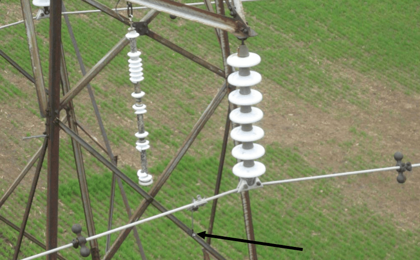
Canada. Arrow shows location of remaining explosive disconnect
and ground lead after operation.
In this case, the disconnect lead is hanging from its clamp, positioned about a third of the way between insulator clamp and the Tebo-Buchanan dumbbell torsional damper to its left. A close-up view (Fig. 7) shows that there are several protrusions, including a metal loop for live-line installation tools. The clamp has been used on many distribution systems but was never intended for corona-free performance at transmission voltages. Fortunately, the arrester mass is not supported by the conductor in this type of configuration and influence of the connecting lead and clamp on vibration behavior is relatively minor.
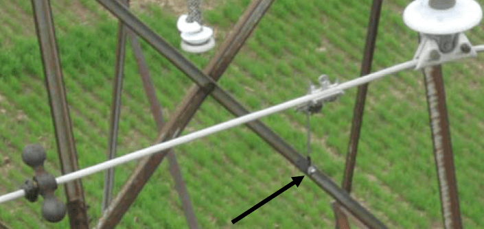
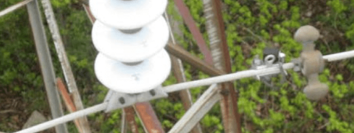
One of the difficulties in making a simple recommendation for existing lines relates to the fact that there is seldom consistent installation practice along an entire line. This, for example, is illustrated in this case by placement of a disconnect-lead clamp adjacent to a Tebo-Buchanan damper (as in Fig. 8).
Arrester Mounted Across Insulator
Many regions of the globe employ arcing horns to protect insulators from arcing damage. Notably, Japan has been development of active arcing horns that incorporate one or two MOR called series varistor units (SVUs), in series, with an air gap as shown in Fig. 9. This type of configuration is an attractive alternative to fixing an NGLA across the insulator since NGLA length generally exceeds insulator length. It also has no adverse influence on vibration damping design.
(Source: Mito/VISCAS).
Near-Term Improvements in Arrester Application Criteria
ELGA in Strut or Cross-Insulator Configurations
Arresters in strut configurations or those mounted across insulator strings add mass to the string. But calculations suggest that this has only minor impact on the imperfect equalization of tension among spans in suspension positions. In the limit of infinite arrester weight, the normal swing of insulators in response to tension differences will be reduced to zero and each span will have a different tension depending on its unique temperature. These types of arrester configurations have no effect on performance of vibration dampers placed on the conductor. The arresters themselves will be subject to normal vibration duty and testing in Clause 8.9.2 of the Standard calls for applying 106 cycles of 1-g vibration to the SVU at its resonant frequency.

NGLA Hung from Conductor
This arrangement has the greatest impact on mechanical characteristics of a line.
Effect of Arrester Weight on Line Clearance
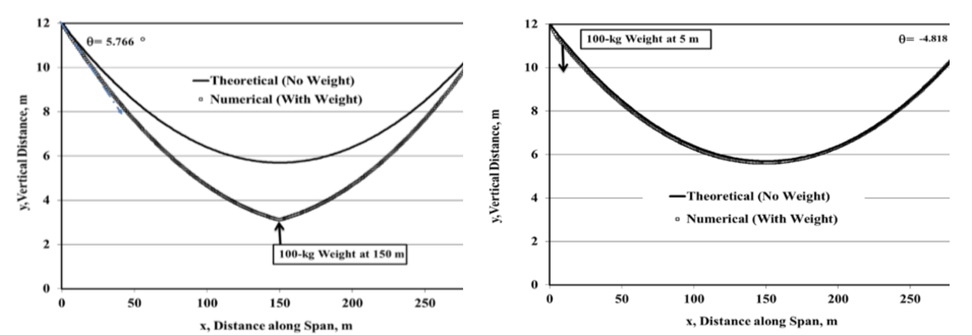
A typical TLSA has a height of about 14.5 mm/kV of maximum continuous voltage (kV line-to-ground). There are different energy duty classes, e.g. IEC Class II or Class III. Analysis shows that arrester weight is approximately 53 g/mm for Class III and 32 g/mm for Class II. Looking for example at the arrester shown in Fig. 5 with its 180 kV MCOV rating, its length is estimated at 2610 mm and its weight is 138 kg. By contrast, weight of a standard 795-kcmil ‘Drake’ ACSR conductor is about 1.63 kg/m and vibration dampers for that conductor fall in the range of 2 to 5 kg. In terms of thermal rating, addition of lumped weight is equivalent to increasing span length by the weight divided by conductor weight per unit length. As such, adding a 100 kg instrument package or arrester at midspan would increase sag of a 300 m span by about 2.6 m, i.e. roughly the sag of a 360 m span.
The numerical calculation of sag with a lumped weight only 5 m from a fixed attachment in Fig. 10 shows relatively minor effect on the catenary and clearance. Adding sufficient weight near the suspension points can actually reduce mid-span sag but at the cost of an increase in line tension that can exacerbate Aeolian vibration issues.
Effect of Arrester Weight on Vibration Dampers
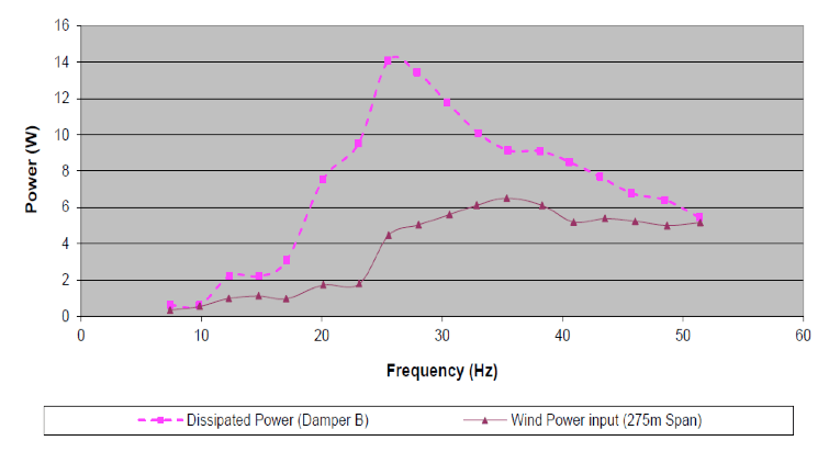
Introduction to vibration dampers takes note of the fact that wind input power to a 275 m span of 795 kcmil Drake ACSR conductor levels out at about 6 W from 25 to 50 Hz. Fig. 11 overlays test data for a damper placed 1 m from the insulator clamp. The damper shows an ability to absorb 14 W at 25 Hz and 6 W at 50 Hz for the same displacement amplitude. Its ability to absorb power in excess of that imparted by the wind protects the conductor from bending strain and fatigue.
Arrester weight is massive compared to typical damper weights of from 0.5 to 2 kg. An arrester forms a new node when placed between an insulator clamp and the vibration damper. This means that the arrester clamp rather than the insulator now needs vibration protection. Advice in an IEEE Technical Report on Aeolian Vibration states: “Surge arresters are specially designed insulator strings comparable in length and mass to the suspension insulators supporting the conductors. These are sometimes suspended directly from conductors. The installation of vibration dampers should be considered on the span side of the surge arrester, at the same distance as they are normally installed from suspension clamps.”
Additional advice by a CIGRE Task Force suggested:
• Key dimension for location of the damper is loop length. Loop length , l,i n metres, is given by ![]() where d is conductor diameter in metres, V is wind speed in m/s, H is conductor tension in Newtons and m is conductor mass in kg/m;
where d is conductor diameter in metres, V is wind speed in m/s, H is conductor tension in Newtons and m is conductor mass in kg/m;
• Loop length and relative motion both change with wind speed, as shown in Fig. 12. Amplitude of vibration in this example is scaled according to the Rayleigh distribution to reflect relative rate of occurrence of different wind speeds. Loop length at highest Aeolian wind speed usually taken as 7 m/s typically falls in the range of one or two metres;
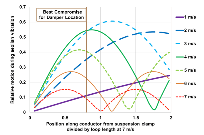
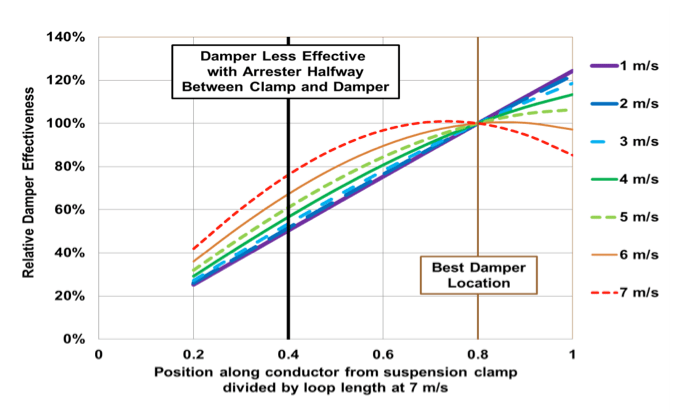
• The damper outside the surge arrester should be placed at 80% of loop length of the highest Aeolian vibration frequency of the conductor from the clamp;
• A wave trap consisting of two dampers separated by this same length can be placed anywhere along the span to suppress Aeolian vibration at the TLSA (e.g. as used in long-crossing spans).
Lack of proper vibration control can lead to serious conductor damage, as shown by the following examples: Separation of sub-spans of conductors from the end point damping is termed Aeolian vibration entrapment. Torsional de-tuning pendulums for galloping control use weights of 15 or 27 kg. On one line strung at unusually high tension, for example, Hydro-Québec noted conductor damage at 367 of 1602 de-tuning pendulum locations after a year of service. Moreover, all aluminum wires were broken at 40 locations. Metallurgical examination confirmed that Aeolian vibration caused fatigue of the Crow 54/7 ACSR conductor with 26.3 mm diameter and 116 kN rated tensile stress. Follow-up testing revealed conductor damage with metal-to-metal clamps after only 16 weeks of exposure in a test span. Compared to this metal- to-metal clamp, attachments with four or six helical rods and the commercial system shown in Fig. 14 all gave reduced bending amplitudes, with six-rod and commercial system staying below the 260 μm peak-to-peak bending amplitude endurance limit. Since line surge arresters have similar or greater weight compared to de-tuning pendulums, it seems prudent to provide a similar or greater degree of vibration protection to reduce fatigue stress to acceptable levels at the conductor attachment.
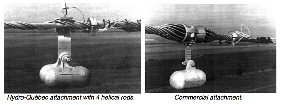
Hydro-Québec attachment with four helical rods; (right) commercial attachment.
Effect of Arrester Weight & Length on Torsional Resonance
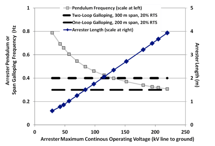
Wind pressure on an arrester will cause torque on the conductor. This can lead to problems of resonance, especially when the pendulum frequency of the arrester approaches the single or double loop galloping frequency of the conductor. Fig. 15 warns that there will be a match of single-loop resonance when a 220 kV MCOV arrester and 200 m span have the same poorly damped 0.3 Hz mechanical resonant frequency. This is in the range of the frequencies that commonly occur during galloping with ice on the conductor.
Tests have suggested that excessive fatigue damage of threaded studs on arresters can occur from 20 k cycles of torsional motion at the galloping/arrester pendulum frequency.
Damage shown in Fig. 16 can be partially mitigated (to 70 k cycles of endurance) if the clamp is tight and flush to the top of the arrester. For more than 70 k cycles, the clamp stays tight but aluminum wires beneath the temporary duckbill live-line clamp start to fail.
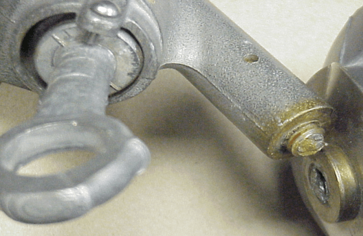
torsional oscillations in laboratory test.
NGLAs Hung from Tower
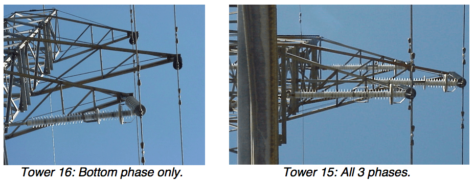
Unlike for EGLAs, IEC standards for NGLAs do not impose requirements for vibration duty. When the relatively light clamps for flexible leads are mounted between insulator and vibration damper, they are near anti-nodes, where vibration amplitude is greatest. When failed arresters, such as those in Fig. 17, are examined closely, the explosive disconnect is usually intact. Instead, the flexible wire has broken at a point of attachment. Arresters can be returned to service by replacing all flexible leads and hardware but this will allow only another limited period of service, e.g. on the order of 5 to 10 years. In locations prone to ice galloping, a longer lead to accommodate longitudinal conductor motion will reduce dynamic stresses at the connectors. Lead failures are usually easy to find since there is considerable corona noise. But they are also a concern, especially when the leads break at the arrester and fall, bringing line potential near to any cross-arms below the phases on double circuit lines. Electrically speaking, the greatest benefit of partial TLSA application is realized with installation on bottom phases, which represents partial mitigation of this possible clearance issue.
There are ways to address limited durability of flexible leads, including:
• Specifications that require limit cycle testing, similar to spacer dampers;
• Specifications that would apply an appropriate number of cycles and amplitude, considering the clamp mounting location and damper let-through frequency;
• Installation practices that would place the disconnect-lead clamp near or on the insulator clamp;
• Use of stress relieving clamping such as over armor rods.
Conclusions
Transmission line surge arresters (TLSA) are large and heavy enough to impact performance of vibration dampers if positioned inappropriately. At a minimum, any existing vibration damper should be displaced along the conductor, treating any conductor-mounted arrester as a new clamp. Concerns with long-term durability of the conductor should include re-selection of appropriate dampers for the new span as well as improved arrester attachment using armor rods or other stress reduction clamps. TLSAs can induce galloping when their pendulum frequency matches span galloping frequency – a possibility when applying 220 kV MCOV arresters on 200 m spans, synchronizing to 0.3 Hz. TLSA accessories, including flexible lead clamps as well as arc receivers for EGLAs, should also be reviewed to ensure that they meet appropriate vibration and flexion criteria for an anticipated service life of 20 to 50 years. Placement of low weight accessories close to existing insulator clamps would be recommended to reduce level of vibration. Since some accessories are about the same weight as vibration dampers, placement near existing dampers should be reviewed with manufacturers and supported by bending amplitude verification tests.
Future Outlook
There is a possibility that a vibration damper could perform the arc-receiver function for an EGLA. While the damper position is fixed by mechanical considerations, it is relatively easy to adjust the support for the SVU horizontally (as in Fig. 18).
The objective of maintaining a constant air gap distance for lateral sway of the conductor can be satisfied if the Aeolian vibration damper weights are positioned at right angle to and possibly above the conductor. Most vibration dampers are directional and their effectiveness would not be guaranteed if installed upside down (above the conductor) when designed for placement below. An elegant solution would therefore require consideration by both mechanical and electrical engineers. Many original installations of arrester tubes have been supported vertically from below. In some cases, on double circuit lines, an extra cross-arm was installed. Fig. 19, for example, shows an NGLA installation on the bottom phase of a steel pole transmission line that uses this approach. Aesthetically, and also considering reliability, it is suggested that placing the arrester a bit higher, modifying the shape of its corona ring and removing the flexible lead completely could yield a satisfactory EGLA installation.
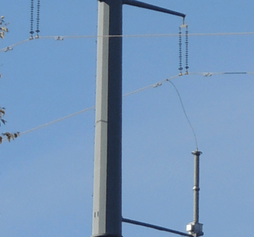
There is an additional benefit to lightning performance, convenient access to optical fibers and ease of helicopter inspection in areas of difficult grounding if an underbuilt optical fiber ground wire (OPGW) is strung from tower-to-tower at the base of the arrester (see Fig. 19). This aerial counterpoise would need to be positioned to provide adequate offset to bottom phase conductors while interphase spacers can also assist in some situations. Underbuilt OPGW, for example, have been applied in Germany on double-circuit lines with single OHGW.

References
[1] R.E. Koch, J.A. Timoshenko, J.A. Anderson and C.H. Shih, “Design of Zinc Oxide Transmission Line Arresters for Application on 138 kV Tower”, IEEE PAS, Vol. 104, No. 10, pp 2675-2680, Oct. 1985.
[2] Newfoundland Labrador Hydro, “Upgrade Transmission Line Corridor, Bay d’Espoir to Western Avalon”, Report to the Board of Commissioners of Public Utilities, Sept. 2011, 47 pp.
[3] T. Short, D. Crudele, J. Harding and C. Perry, T&D System Design and Construction for Enhanced Reliability and Power Quality, EPRI, Palo Alto, CA: 2006, 1010192, 366 pp. Available (free) at www.epri.com.
[4] IEC 60099-8 Ed. 1.0: Surge arresters – Part 8: Metal-oxide surge arresters with external series gap (EGLA) for overhead transmission and distribution lines of a.c. systems above 1 kV, 2010.
[5] M.V. Lat and J. Carr, Application Guide for Surge Arresters on Distribution Systems, CEATI, Montreal, Canada: 1987. 077-D-184A. 376 pp.
[6] W.A. Chisholm, Guidelines for the Installation of Surge Arresters on Sub-Transmission and Transmission Lines Using Different Structure Designs at Voltages from 69 kV to 345 kV, CEATI, Montreal, Canada: 2005. T033700-3312A. 140 pp.
[7] J. Williamson, “Lightning Protection and Surge Arrester Application on NB Power Transmission Lines”, Proceedings of 2008 IEEE PES T&D Conference and Exhibition, Chicago, IL.
[8] CIGRE WG B2.21, On the use of power arc protection devices for composite insulators on transmission lines, CIGRE, Paris: Technical Brochure 365, Dec. 2008, 19 pp.
[9] W.A. Chisholm, “Mechanical and Environmental Considerations in Transmission Line Surge Arrester Applications”, Invited Lecture, XII SIPDA, Belo Horzonte, Brazil, 7-11 Oct. 2013.
[10] Aeolian Vibration TF of Overhead Lines SC, An Introductory Discussion on Aeolian Vibration of Single Conductors, IEEE, Piscataway NJ: Technical Report PES-TR17, Aug.. 2015, 37 pp.
[11] Preformed Line Products, Dogbone® Vibration Damper, EN-SS-1090, 2011.
[12] P. Van Dyke, C. Hardy, R. Dansereau, Y. Blanchette and J.-G. Gagné, “Hydro-Québec’s Experience with Anti-Galloping Pendulums”, Canadian Electrical Association Meeting, Vancouver, B.C., Mar. 1995. 10 pp.
[13] C. Ramirez and G.E. Harper, “Improvements to the protection of overhead transmission lines using lightning detection system in the Mexican Yucatan Peninsula”, CIGRE IntColloq Lightning Power Sys., Lyon, May 2014.
[14] CIGRE TF B2.11.03, “State of the art survey on aircraft warning markers: Experience with current practice”, Electra, No. 224, pp. 24-29, Feb. 2006.
[15] M.L. Lu and M. Orth, Predicting the Failure of Line Post Insulator Mounting Studs Die to Aeolian Vibration, EPRI, Palo Alto, CA and Pinnacle West Capital Corporation, Phoenix, AX: 2006. 1013245.
[16] D. G. Havard, Dynamic Loads On Transmission Line Structures During Galloping – Field Data and Elastic Analysis, Fifth International Symposium on Cable Dynamics, Santa Margherita, Italy, 15-18 Sept, 2003.