The 38 kV to 110 kV Line Uprate Feasibility Study in Ireland introduced an outline for a compact distribution standard 110 kV line design. This design is tailored to the Irish context to enable conversion of existing 38 kV overhead lines to 110 kV, utilizing the same or similar structures and in the same locations as those they are replacing. This approach increases capacity along selected line corridors while leveraging existing infrastructure as well as minimizing environmental and community impact. It also has the potential to significantly accelerate capacity delivery to meet the net zero energy transition.
The 38 kV network in Ireland comprises about 6000 km overall length and includes some 500 separate overhead line circuits. Since loading has increased in recent years, voltage constraints have developed on the rural 38 kV network and this ageing network requires large scale asset replacement. The 110 kV voltage is already being used for both transmission and distribution.
The voltage uprating would target an increase in thermal power capacity from typically 20 MVA to 100 MVA (the current maximum distribution / transmission interface capacity) while addressing voltage constraints in the network.
Furthermore, this work identifies opportunities to introduce innovative materials such as composites (poles, cross-arms, composite core conductors, insulators, etc.). This will help prepare for and meet future regulatory changes and standards that may impose stricter requirements on infrastructure resilience and environmental impact.
Review of International Practice
Below is a brief review of international practices for compact line design.
ENA Standard Trident Design: UK Practice
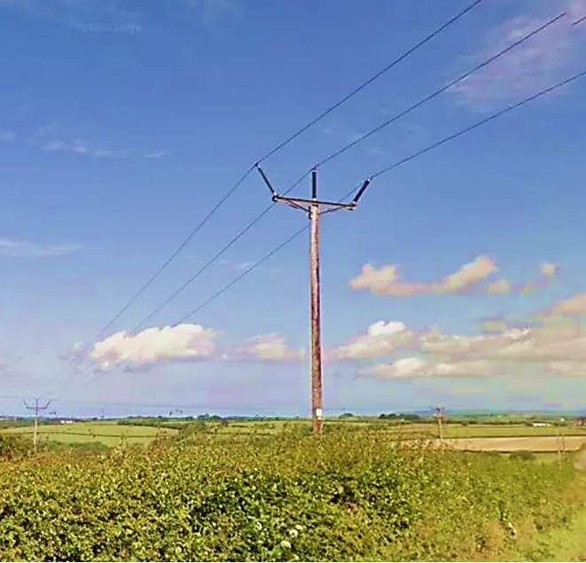
A good starting point is a review of UK practice and experience with the use of the Trident Wood Pole Design. This commenced in the 1980s and was originally based on ENA Technical Specification ENA TS 43-50 published in 1984. The Trident design featured single and portal wood pole post insulator intermediate structures along with portal strain angle and failure containment structures. A key disadvantage of the design is the extensive use of stays on the angle and failure containment structures. However, this reduces cost and simplifies construction, particularly in remote locations and therefore offers significant environmental benefits. Figs. 1 and 2 provide examples.

Finland
![]()
Eltel introduced the SlimLine concept on their network in 2005 (see Fig. 3). This replaced existing portal type construction of 110 kV lines (which featured stay wires). The SlimLine design, which is a compact Delta configuration design, generally includes a shield wire. It has been used to replace existing 20 kV lines increasing resiliency from better management of vegetation corridors which are significantly reduced from a nominal 26 m for existing 110 kV portal design (not dissimilar to ESB grow-in restrictions) to just 15 m in 110 kV SlimLine.
Slovenia
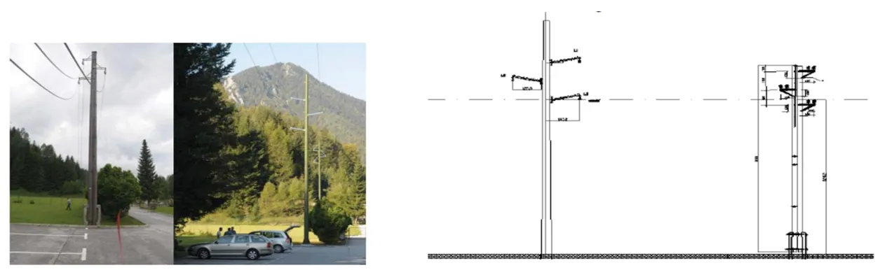
An example from Slovenia comes from a CIRED paper on experience uprating 35 kV lines to 110 kV using compact steel poles. In this case, the emphasis was on replacement with structures that were similar dimensionally and aesthetically. Planning permission was sought specifically on this basis for the 20 km line which runs in Northern Slovenia along scenic Upper Sava Valley between the towns of Jesenice and Kranskja Gora. Height to the lowest phase was maintained. Fig. 4 shows an example of both old and new structures.
USA/Canada
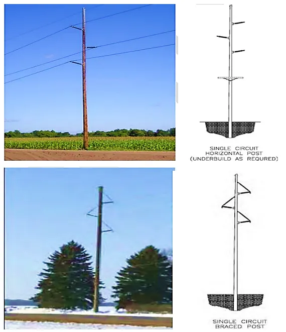
Single pole line constructions comprised of steel, wood or composite materials are common in the USA and Canada given the advantages of compaction, facilitation of shield wire placement and ability to also carry distribution lines below the transmission phases. However, these lines are often built in urban or suburban areas and along roads with short spans being typical to lower pole height.
Brazil
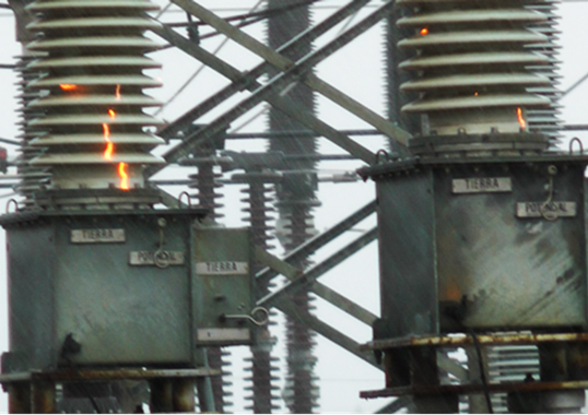
Included in CIGRE Technical Brochure No. 353 is an example of a 69 kV to 138 kV line uprating solution (see Fig. 6). This portal configuration of 69 kV line uses live line structure replacement to install new poles ready for a new portal and replacement of insulators. As the increase in capacity was noted to be from 50 MVA to 100 MVA, it can be assumed that the conductor remained unchanged.

Plan to participate at the 2025 INMR WORLD CONGRESS in Panama. Muhammad Shariq Hassan, Sr. Distribution Engineer with ESB Networks in Ireland will explain how the challenges in creating a compact line design for upgrading 38 kV lines to 110 kV lines were addressed. He will also review international practice related to upgrading networks and provide insight into key design considerations for 110 kV overhead lines. His presentation will include sample design analysis and impact assessment based on existing 38 kV line corridors considered to be representative of this network in Ireland.