Ensuring a reliable medium voltage distribution network requires that cable components can withstand electrical, mechanical, thermal and ambient stresses. One of the main degradation factors in insulation behavior is water. If sufficient tightness of cable joints or of the cable shield is lacking, water ingress can influence the inner interface and lead to an internal puncture. Several construction methods are used to protect this critical inner system and inner joint from water.
This edited past contribution to INMR by Mario Dreßler and Prof. Stefan Kornhuber at the University of Applied Science Zittau/Görlitz as well as Stephan Arndt and Christian Taube of BBC Cellpack in Germany reviewed a test procedure developed to verify tightness and functionality under extensive water stress. A test stand allowing combined stress with water and medium voltage was designed and cable joints without outer protection systems were investigated for up to 10 years. Some were stressed with continuous voltage stress and others at a certain test interval. In addition to continuous stress by water and voltage, breakdown voltage tests, PD tests and visual examination were conducted after dismantling.


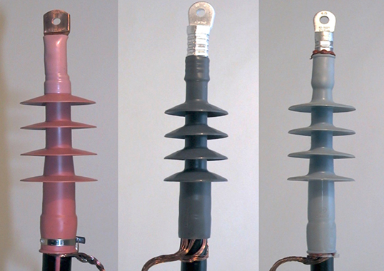
Service experience and testing have together helped improve the outer tightness of cables and accessories such as joints. As a result, the cable protection shield as well as sealing of the outer protection of joints provides the required tightness for different cables and cable diameters. Technologies used in this regard include epoxy resin field boxes as well as hot and cold shrink protection systems.
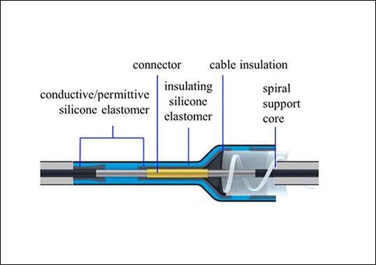
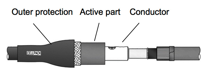
Fig. 1 shows an example of a joint consisting of three main parts: outer protection box, active insulation part and conductor connection clamp. The active insulation is responsible for control and homogenization of electric field in this section, starting from the pure radial field in the cable over the conductor clamp to the radial field in the cable.
Electric field control can be realized using different techniques but, due to manufacturing purposes, these parts of the joint are assembled with shrinking components that provide a physical interface. For example, this physical interface between cable insulation and the joint material (e.g. silicone) allows for different electrical withstand voltages depending on pressure, roughness, temperature, materials and humidity. Using stable long-term pressure allows achieving good ageing performance of this interface. Nonetheless, in spite of the tightness of the cable shield and outer protection box of a cable joint, there is still the possibility that small amounts of water can enter the cable, due for example to minor damage in the outer protection. This can influence the interface, which is stressed by the electric field but no longer being sufficiently weakened. For this reason, several investigations were conducted using cylindrical model arrangements, including long-term investigation to evaluate the electrical withstand of this physical interface in combination with water stress.

Test Set-up
Investigation of Cylinder Model Arrangement
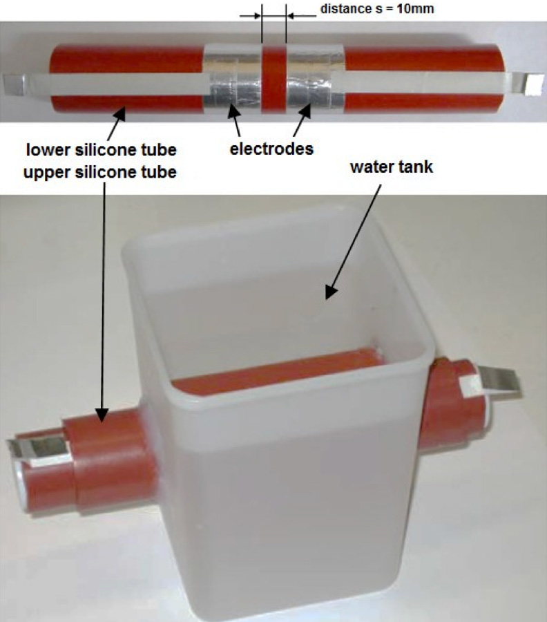
In order to investigate possible diffusion of water into the interface, a cylinder model was used. A silicone tube is mounted on a solid rod and thin metallic electrodes are positioned onto the silicone at a defined distance. After that optional a layer can be added (for simulation of paste in a real joint) and a second silicone tube, which is stretched during the mounting process, is positioned above the whole arrangement. The pressure between the silicone tubes (at the interface) can be varied by different diameters and elastic modulus of the second silicone tube.
This described cylinder model is suitable for water long term investigations, because in this setup only a water diffusion through the material (transverse to the surface and interface) is possible like at bottom part of figure 2 is visible.
To increase the speed of the diffusion of water these test objects were put into a climate chamber at 50°C for certain time.
Long-Term Evaluation
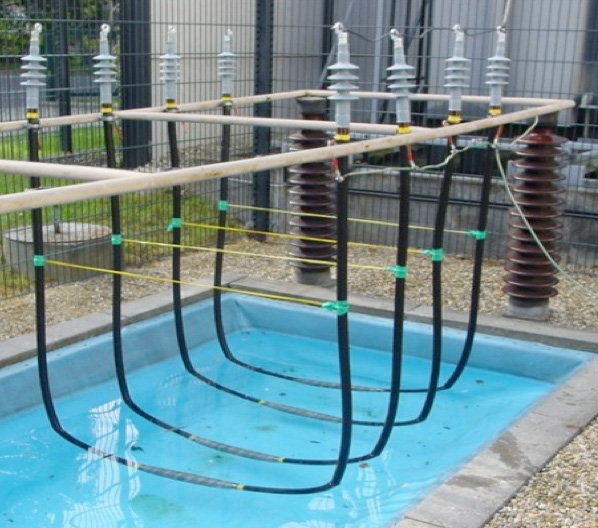
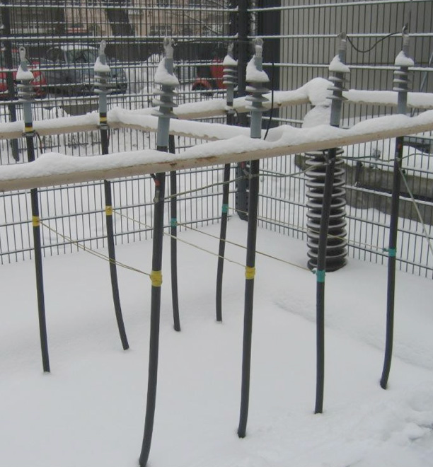
Beside the investigations with the cylinder model arrangement long term investigations with real cable joints in an outdoor water test basin were carried out. With this test setup the transfer of the results of the cylinder model arrangement should be investigated. In figure 3 two pictures of the test setup are shown at summer and winter. At this test setup cable joints were installed over years (including different weather conditions) and a test voltage was applied on a continuous and an interval level.
Results of Water Diffusion Test with Cylinder Model
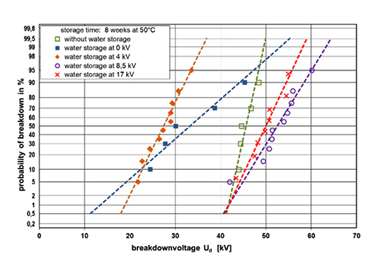
The breakdown voltage was measured at the cylinder models by using the voltage rise test with a voltage increasing speed 1 kV/s. The test samples were aged in different conditions and some samples got a continuous voltage stress over the whole time. After the aging time (8 weeks) the breakdown voltage for the in water aged cylinder test models was measured by using the voltage rise test. The results are shown in Fig. 4.
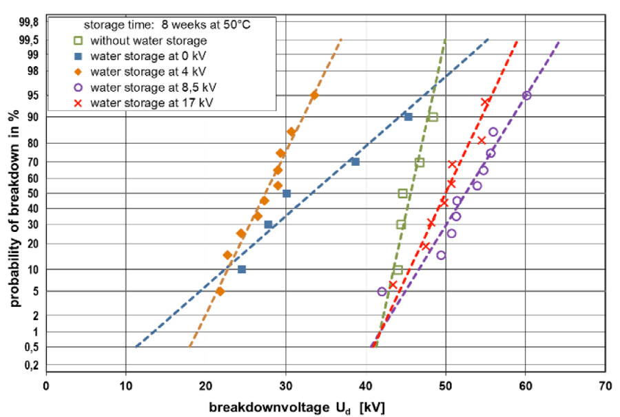
Due to the water stress a reduction of the break down voltage of the interface can be observed for test samples without a continuous voltage stress and with 4 kV voltage stress during the storage procedure. For test samples, stressed with 8,5 kV and 17 kV during the water aging time no reduction of the breakdown voltage after the aging period can be observed.

Long Term Evaluation of Cable Joints
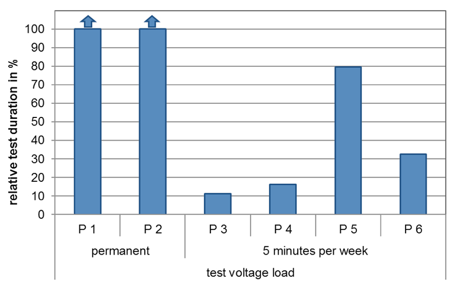
Based on the evaluation with the cylinder model the evaluation at cable joints with water stress were set up. The cable joints got no outer protection shield and were put into the water basin in the outdoor test facility of the High Voltage Lab of the University of Applied Science Zittau / Görlitz. This setup provides an extreme stress compared to a regular stress out in the field. At the test object, continuous or intermediate voltage stress was applied. At the test objects with the intermediate voltage stress the test voltage was applied 5 minutes per week. The test voltage was few times higher than the operation voltage in the field. The test objects were tested for several years. The results are summarized in figure 5. The test samples, which marked with an arrow indicate, that these samples did not break down during the testing time.
The investigated test samples with a continuous voltage stress have shown a longer lifetime at this long-term test as the test samples with the intermediate voltage stress. After the test period the breakdown voltage of the test samples was examined by using the voltage rise test. The breakdown voltage was significantly above the required test voltage according to the type test and achieved values in the range of the break down voltage of new test samples. In further investigations the partial discharge inception voltage was measured at cable joints with no outer protection arranged in a waterbasin. They applied also with and without permanent test voltage during the test time. Fig. 6 shows the results. The partial discharge inception voltage presented in percent to the first value at the start of the test.
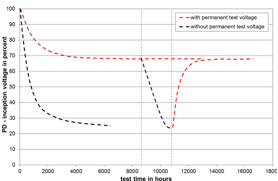
For test samples with a continuous voltage stress the partial discharge inception voltage is slightly reduced after starting the test and a stable value starting with 2000 h can be recognized. For test samples with an intermediate voltage stress a different behavior can be observed. During the time without a continuous voltage stress the partial discharge inception voltage is declining. After stressing the test samples with voltage again the partial discharge inception voltage is increasing back to approximate the values before the interruption of the test voltage.
The phased resolved partial discharge (PRPD) pattern also shows differences between measurements at dry and water stressed cable joints. In figure 7 the PRPD pattern is shown for the cable joints before starting the test (left) and the PRPD pattern during the water storage test (right).
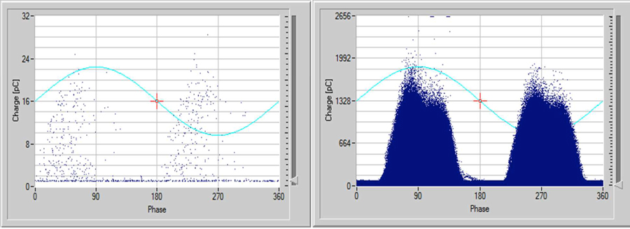
Comparing these to patterns it can be recognized that beside the cumulative distribution of partial discharge events the phase relation is shifted from the 1st and 3rd quarter to the maximum of the test voltage. To explain this behavior of the dependence of the breakdown voltage and the partial discharge behavior with continuous and intermediate voltage stress two possible effects must be considered:
• the voltage stress provides leakage current and or partial discharge for the interface in combination with possible water content so that the interface is dried by these losses and
/ or
• the electrical field in the interface prevents the diffusion of water into the interface and into the material, as well.
Currently different investigations with electrical and chemical test methods are in consideration or in feasibility tests to identify the physical processes.

Summary & Conclusions
Medium voltage cable distribution networks have been increasing over the last 30 years. Beside the development and test according to the water tightness of cable and cable joints, there might be a possibility that low amount of water can enter the outer shield, which might influence the electrical behavior and the breakdown voltage of the longitudinal interface. For this reason, investigations at cylinder test models were done. With the results of the cylinder test model a dependence of the breakdown voltage and the water immersion could be recognized. However, if a certain voltage stress continuously exists the breakdown voltage is not affected by the water storage test.
For testing the transferability of the cylinder model to real cable joints long term tests with continuous and with intermediate voltage stress in an outer water basin were done. The test samples were tested for several years.
The results confirm the experience of the cylinder model investigation and proof that the cylinder test sample model is valid to test the behavior of this interface. The results show also that the investigated medium voltage cable joints, stressed under these extreme conditions, provide reliable and long-term stable interface insulation.
References
[1] J. Pilling, K.-D. Haim, R. Bärsch, 2001, “The Advantages of Silicone Rubber in Cable Accessories for Medium Voltage Application”, Distribution 2001, Brisbane, paper No. 42.00
[2] R. Bärsch, V. Berthold, J. Pilling, J. Hofmann, 2005,
“Grundlagenuntersuchungen zum Isoliervermögen von Silikonisolierungen mit Interfaces zur Entwicklung kompakter Mittelspannungs-Kabelmuffen”, ETG-
Fachbericht 99 (2005), S. 195-200
[3] A. Eigner, S. Semino, 2008, “Ermittlung des Anpressdruckes von Silikonisolierungen und dessen Einfluss auf das Isoliervermögen von Grenzflächen”, ETG-
Fachbericht 112 (2008), S. 193-196
[4] D. Kunze, 2000, Untersuchungen an Grenzflächen zwischen Polymerwerkstoffen unter elektrischer Hochfeldbeanspruchung in der Garniturentechnik VPE-isolierter
Hochspannungskabel, Dissertation Universität Hannover 2000
[5] J. Oesterheld, 1995, Dielektrisches Verhalten von Silikonelastomer- Isolierungen bei hohen elektrischen Feldstärken, Dissertation TU Dresden 1995
[6] M. Dreßler, S. Kornhuber; R. Bärsch, G. Jacob, B. Knüpfer, 2016, “Kurz- und Langzeitisoliervermögen von polymeren – Feststoffisolierungen mit makroskopischen Längsgrenzflächen”, VDE-Fachtagung Hochspannungstechnik 2016