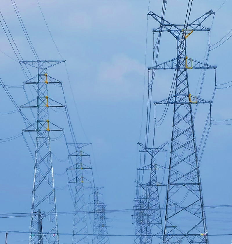
There is now a clear trend and requirement to meet higher power demand in limited corridors and using narrower right-of-ways. While function and performance dominated planning and design in the past, aesthetics, environmental impact and land-use have now become the key drivers for many overhead line projects. In fact, compact transmission lines continue to gain in importance over traditional designs and for some utilities have become the standard for all new systems, especially in urban areas.
This edited contribution to INMR by Usama Ahmed, Transmission Solutions Manager at Shemar Power in Canada proposes integration of two technologies – composite insulated cross-arms (CICAs) and externally gapped line arresters (EGLAs) to yield the ultimate opportunity to compact overhead lines. He summarizes how this is accomplished, related insulation coordination issues and opportunities for a truly optimized line design.

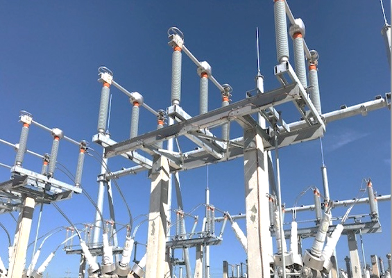
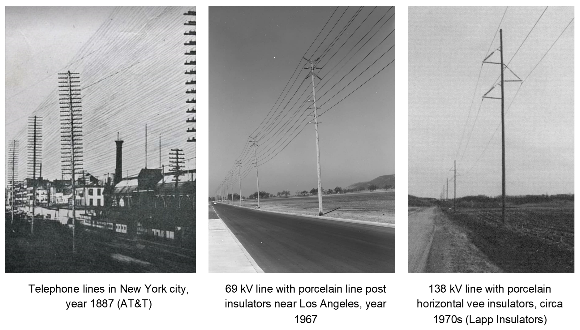
Although compact lines have received growing attention during recent years, the concept has existed for a long time. The earliest example traces back to the late 19th century when telephone lines were erected in New York City on wooden poles featuring up to 25 cross-arms and 500 pin insulators on a single structure. In the field of high voltage transmission, compact line designs were initially deployed to solve right-of-way constraints in congested areas. Porcelain line post and horizontal vee insulators were typically used in these attempts, starting in the 1960s (see Fig. 2). Unlike suspension insulators supported by davit arms, the post insulator arrangement controls conductor position and enables reduced phase-to-ground and phase-to-phase clearances. As such, required right-of-ways are narrower with slimmer, less obtrusive structures.
The advent of composite insulators marked one of the most important milestones in the field of overhead line design and these have become the choice for compact line applications due to their low visual profile as well as high strength and flexibility as insulated cross-arms. With advancement and maturity of this technology, it has now .become possible to design and manufacture different configurations of high-strength composite insulated cross-arms for virtually any line loads and up to the highest system voltage. The CICA plays a vital role in realizing compact line projects and provides engineers with a range of opportunities to produce compact, lighter head designs to manage today’s challenges
Externally gapped line arresters (EGLAs) are typically installed for reliability considerations and in efforts to improve lightning performance. As with the trend toward greater use of CICAs, application of EGLAs on transmission lines is progressively becoming mainstream in modern grids. If properly designed, application of EGLAs alongside CICAs allows for truly optimized line design by substantially reducing required clearances and insulator arcing distances.

Insulator Solutions for Line Compaction
Line compaction involves the process of reducing the spacing of phases from the support structure as well as between each other. The present state-of-the-art in line compaction relies on fixing phase conductor motion, eliminating non-insulating steel/wooden cross-arms and eradicating the space required by conventional suspended insulator strings.
Contemporary insulator solutions for line compaction include line post, braced line post (BLP), pivoting braced post or horizontal vee and CICA. The fundamental difference between these options is mechanical strength. Line post insulators are loaded flexurally and typically applied up to 138 kV with single phase conductors and short spans. Braced line posts, usually used up to 230 kV, have a higher vertical load capability but the same limited transverse and longitudinal capacity as line posts.
Pivoting braced line posts feature a hinged versus a fixed base connection of the post insulator to the support structure. This allows the assembly to pivot and handle higher differential longitudinal loads. Pivoting (rotatable) braced line posts have been applied up to 345/400 kV but require careful analysis and design with respect to wind stability. Stability considerations of pivoting braced posts impose restrictions on span length and require frequent restraint supports along the line to stabilize sections with hinged bases.
Finally, insulated cross-arms are mostly custom-designed. The CICA is a high strength solution that can provide like-for-like replacement of conventional steel cross-arms and enable line compaction for even the highest system voltages (e.g. 1000 kV AC and ±1100 kV DC) with heaviest conductor bundles and with no restriction on allowable spans or security of mechanical loading.
Some might argue that conventional vee strings are also a form of compact line insulator arrangement. However, this configuration can only be regarded as a semi-compact solution because, while it restricts conductor movement, the vee string still requires a long cross-arm for attachment and occupies a large volume of space in the structure head.
It should be noted that the definition or categorization of insulated cross-arms and the term CICA varies across different regions of the globe. In North America and in the United States for example, line posts and braced line posts are distinguished from insulated cross-arms which are defined as arrangements having two post insulators in a triangulated configuration. In Europe, braced line posts (both rigid and pivoting types) are also categorized as insulated cross-arms. By contrast, in China, which has perhaps the purest definition, all types of line posts, braced line and three-dimensional combination arrangements of post and brace insulators subjected to a combination of tensile, flexural and/or compression loads are defined and identified as insulated cross-arms (or CICAs). This latter definition is applied in the discussion below.
Today, development, application and increased acceptance of CICAs on EHV and above (≥ 345 kV) transmission lines have taken place mainly due to:
• Growing demand for line compaction and upgrade retrofits for progressively higher voltages and critical applications;
• Commercially available FEA tools that enable customized electrical and mechanical designs and rapid prototyping;
• Availability of standards, such as the soon to be published P2833, IEEE Guide for Overhead Transmission Lines with Composite-Insulated-Crossarm Supports;
• Maturity and reliability of composite insulators, advancements in material science and, most important, the ability to manufacture high-strength and relatively large diameters and sizes of FRP solid and hollow cores for post insulators.
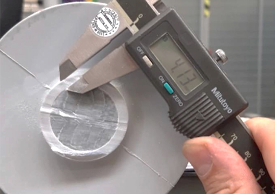
As section lengths of post insulators increase due to electrical requirements, larger FRP core diameters are required to sustain the applicable bending and buckling loads. An extreme example can be seen in Fig. 6 which shows a 1000 kV double vee CICA. Due to the high buckling load requirements and a section length of over 11 m, the post insulators employed φ470 x 17 mm hollow core FRP tubes manufactured with filament winding and optimized for high bending strength.
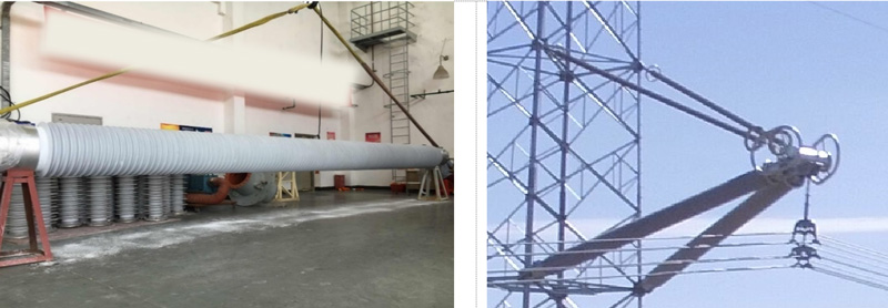
Fig. 6: 1000 kV CICA with 2×840 kN brace strength and φ470×17 mm hollow core post insulators of 11m section length manufactured with injection molded HTV silicone rubber.
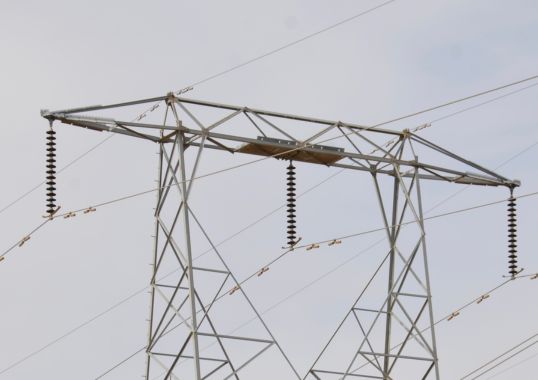
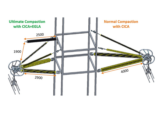
During design of a CICA, the basic aim is to set the minimum possible clearances to reduce cross-arm length and maximize compaction. The extent of compaction is controlled by insulation coordination requirements. These involve selection of the shortest air gap clearances and insulator lengths consistent with the specified reliability of line operation under expected power frequency, lightning and switching overvoltages. Even with the same phase-to-ground clearances, use of CICAs can bring about substantial compaction of transmission structures. Fig. 7, for example, shows two 220 kV double circuit transmission lines designed for the same reliability.
EGLA Integration with CICA
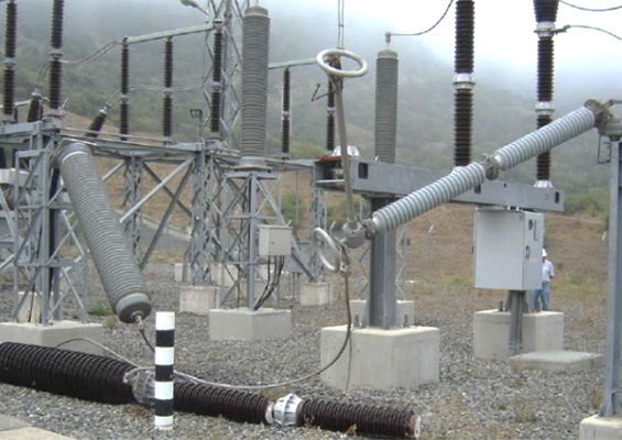
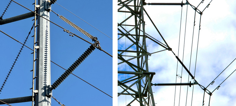
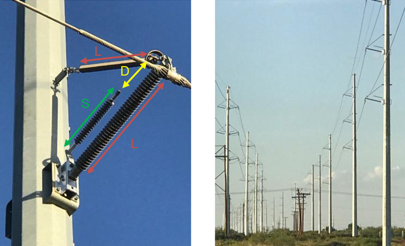
The EGLA is a transmission line dedicated surge arrester, installed in parallel to line insulation and protecting it from lightning overvoltages. Fundamentally, it consists of an external air gap in series with a series varistor unit (SVU). In the event of lightning strike, the air gap sparks over (before the protected line insulation), the SVU clips the surge voltage and the follow current is extinguished without requiring any breaker opening operation. During mounting of the EGLA assembly, maintenance of a constant air gap distance is crucial for reliable sparkover operation. Integration of an EGLA with a CICA provides an extremely stable and static air gap that does not change with wind induced motion of conductors (see Fig. 8).
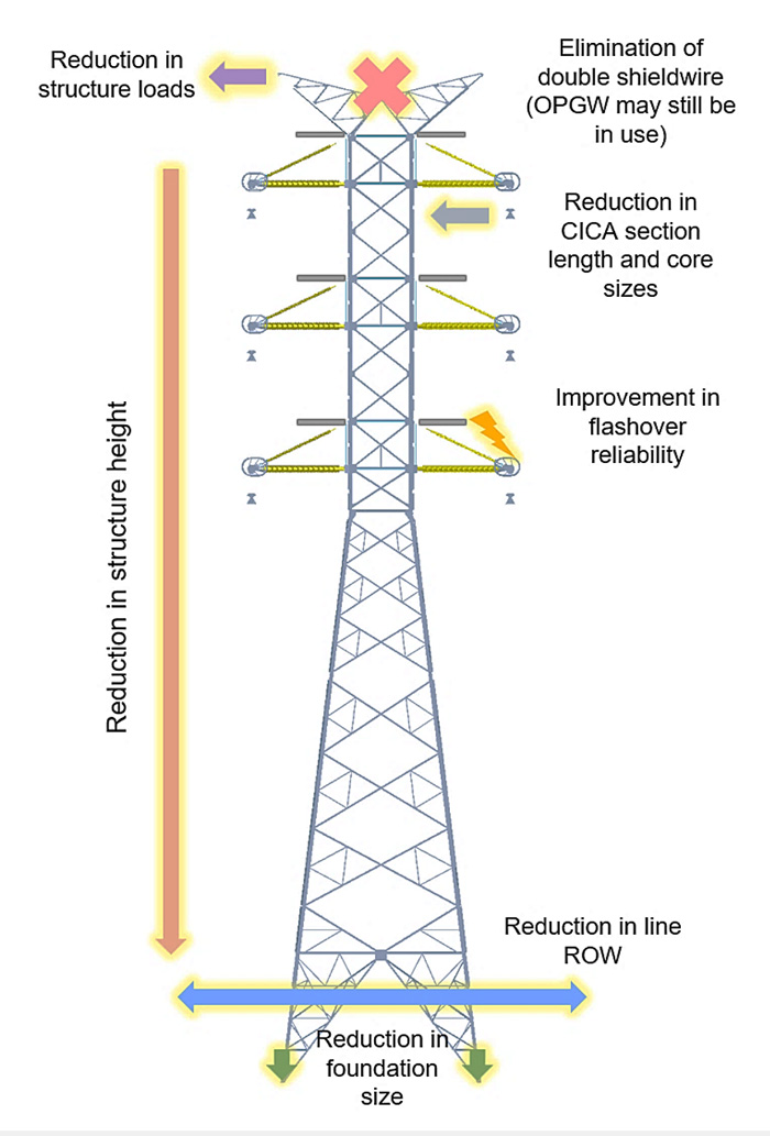
EGLA integration can bring the CICA compaction opportunity to the next level. With an EGLA applied, the traditional method of line insulation coordination is no longer relevant. During a lightning event, flashover can only occur across the EGLA’s air gap. Taking the EGLA’s operating principle into consideration, the required dry arcing distance of CICAs can be reduced. The lightning withstand level of the CICA is coordinated with the EGLA’s protective level, which is defined by the sparkover voltage of its series gap. The lightning impulse flashover voltage of the EGLA becomes the decisive factor determining the CICA’s dry arcing distance. This assumes that switching overvoltages can be effectively suppressed through other means such as breaker pre-insertion resistors, controlled switching and non-gapped line arresters.
Fig. 8 depicts the ‘trickle-down’ effect of EGLA application. Both the section length of the CICA and required core diameter of the post insulators are reduced, meaning right-of-way is further compacted. Overhead shieldwire(s) can be omitted and wire loads as well as resultant foundation over-turning moments are reduced – all culminating in an ultra-compact, lighter, discrete and more economic structure. Apart from the physical compaction benefits, and with EGLAs protecting each phase, the transmission line also becomes virtually lightning proof, thus lowering maintenance costs.
In situations where EGLAs are used primarily for line compaction, the aim should be to minimize (as much as technically possible) their air gap and protective level since this will directly impact required CICA insulator arcing distance. It should be noted that the sparkover voltage of the EGLA assembly will be greater than that of the series gap alone. Minimum EGLA air gap (D) is determined by the maximum switching overvoltage of the system, which it must withstand with a shorted-out SVU under wet conditions. Section length of the SVU itself (S) is determined by required rated voltage, pollution considerations and the need to withstand 1.4 times the residual voltage of the arrester at nominal discharge current.
Any lightning flashover should occur in the EGLA air gap and not on the protected insulator. Based on the EGLA air gap selected, minimum CICA dry arcing, or more appropriately the assembly’s strike distance (L), is determined through coordination between EGLA flashover and insulator withstand characteristics, including a specific protective margin of X = 2.5, as recommended by IEC 60099-8:
U50 EGLA (1 + 2.5 * 0.03) < U50 INSULATOR (1 – 2.5 * 0.03)
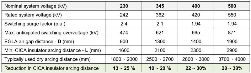
Table 1 summarizes results of typical insulation coordination calculations of CICA and EGLA combinations using formulas given in Hileman’s book as well as data published by various arrester manufacturers. Switching surge factors have been taken as the typical levels experienced on transmission systems of different voltages.

As can be seen, degree of compaction increases with higher system voltages due to more effective switching surge suppression in EHV systems. If added aggressive measures are adopted to decrease switching surge factor, further improvements in compaction can be achieved. The reduction obtained in insulator arcing distances and clearances can also be used in voltage uprating scenarios to upgrade existing line capacity. It should be noted that the values in Table 1 are indicative only and actual sizing and coordination of EGLA and insulator air gaps have to be verified through in-situ laboratory testing.
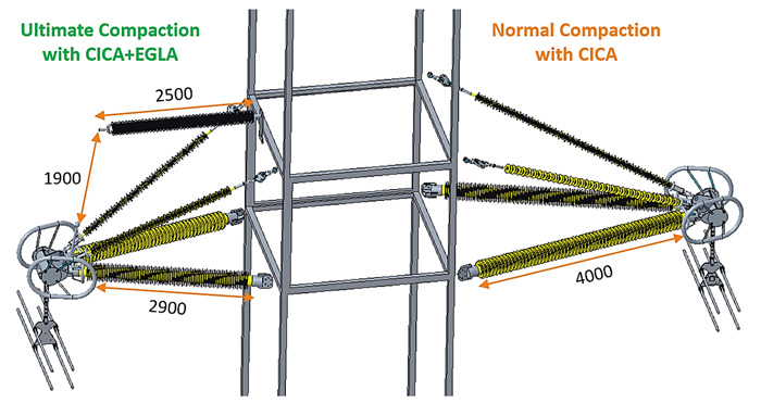
To further analyze integration of CICA and EGLA, focus is placed specifically on the 500 kV case. If the EGLA SVU and air gap are placed in the same plane as the CICA post insulators, the total series length of the EGLA assembly then becomes greater than the optimized CICA post insulator section length (as can be seen in Fig. 9). If the mounting scheme shown in Fig. 10 is used, the benefit of CICA dry arcing reduction cannot be achieved because the horizontal length of the CICA would need to be increased to accommodate the longer assembly length of the EGLA. Therefore, an optimal physical set-up of the CICA+EGLA combination should be explored to achieve the goal of ultimate compaction.
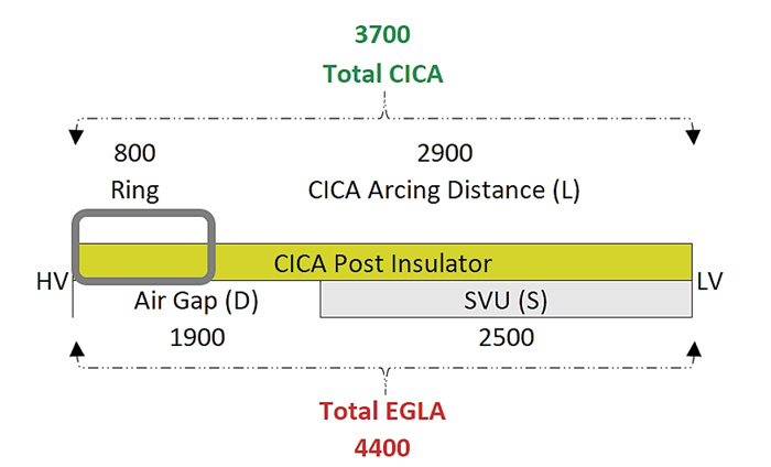
Fig. 10 shows a possible physical integration of an EGLA on a 500 kV double Vee CICA structure. This proposed mounting set-up fulfils the following important factors to ensure ultimate compaction and reliable operation:
• Simple and uncomplicated design;
• Ease of inspection and maintenance;
• Static and adjustable length of EGLA air gap;
• Insensitive to variations in SVU length;
• No interference with above phase bundle;
• Adequate clearance around the HV end of the SVU from the grounded hardware;
• Realization of most compact CICAs possible.
In-span interphase insulating spacers can form part of a compact overhead line construction, especially in areas prone to conductor ice accretions. The ultra-compact line would result in even more amplified electric-field stresses which would necessitate careful analysis with FEA tools and adequate design of grading devices. Use of inclined or horizontal composite insulators in CICA assemblies improves ice performance of the line and selecting insulators with hydrophobic surface properties reduces risk of contamination flashovers.
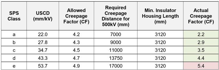
However, reduction of insulator section lengths entails an increase in the creepage factor (CF) of the insulators. Table 2 provides a snapshot of this situation. For the 500 kV case, the creepage factor recommendations of IEC 60815-3 can be maintained except for heavily polluted site contamination severity. There may also be a limitation for transmission lines in heavy icing and/or snow areas where insulator dry arcing distance should be able to withstand ice accretion and bridging, without causing flashover.
It is worth noting that in CICA applications where the insulators are mechanically loaded in cantilever, reduction in the required arcing distances with EGLAs not only decreases the section length but also the FRP core size of the post insulators. This is because shorter line posts are more resistant to bending and compression buckling loads.
Fig. 11 shows the geometry and component insulator approximate reaction loads for a quad bundle 500 kV line under broken wire condition (Vertical = 47 kN, Transverse = 8 kN and Longitudinal = 95 kN). This condition was found to be the controlling load case for mechanical dimensioning of the CICA assembly. The marked-up insulator section lengths were derived considering presence of appropriate grading rings.
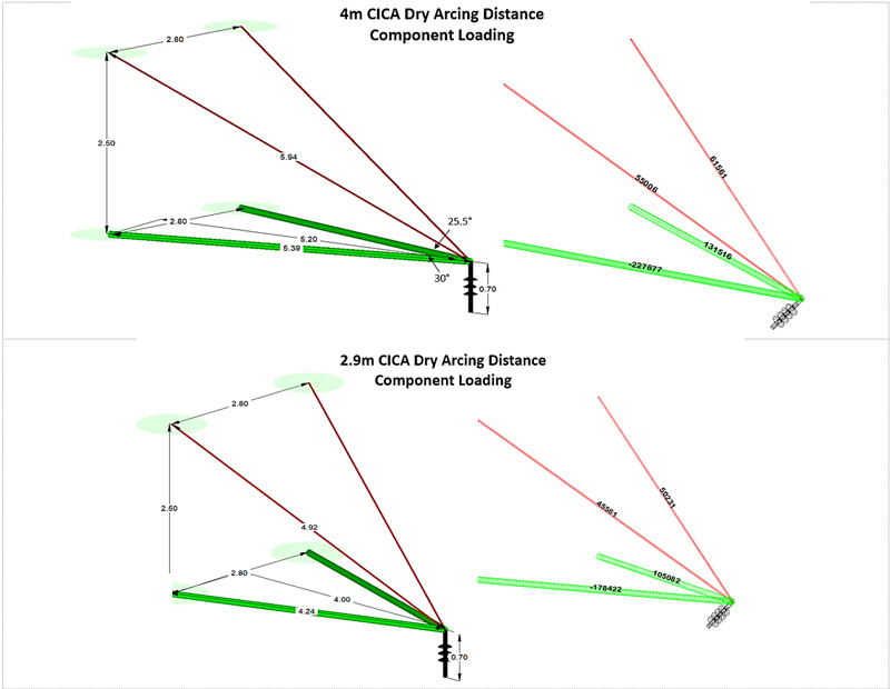
For the specified compression load (SCoL) rating, which includes a conservative safety factor of 1.5 on the actual in-service compression loads and buckling lengths of 5.4 m and 4.2 m respectively, the cross-section diameters of CICA post insulators are determined to be: φ200×10 mm hollow core for the compact CICA assembly; and φ160×10 mm hollow core or φ130 mm solid core for the ultra-compact CICA + EGLA integrated assembly.
Application of EGLAs and CICAs obviously entails an additional cost component. But this will be offset with potential reductions in insulator size, support structure/foundations and right-of-way land requirement as well as by savings from eliminating overhead shield wire(s).

Summary
The true potential of innovative technologies such as CICAs and EGLAs can be exploited by optimizing transmission structures and improving power supply reliability. As global focus shifts towards more sustainable development, there is now increased emphasis on reducing the environmental impact of new transmission projects. Greater public acceptance of aesthetic designs has also become a crucial consideration.
The combination of CICAs and EGLAs can deliver ultimate compaction of overhead lines by reducing required space and clearances. Such highly compacted lines will better meet today’s diverse challenges confronting power utilities and project developers.
Bibliography
[1] EPRI Transmission Line Reference Book: 115– 400 kV Compact Line Design, 2018 Edition.
[2] R. A. Bernstorf, “Composite Braced Line Posts – Mechanical Considerations”, INMR World Congress, 2011.
[3] U. Ahmed, F. Janjua and X. Zhang, “Applications and Design of Composite Insulated Cross Arms,” 2022 IEEE/PES Transmission and Distribution Conference and Exposition (T&D), 2022.
[4] F. Giraudet, “Externally-Gapped Line Arrester Technology: Background, Development & Future Directions”, INMR World Congress, 2022.
[5] F. Giraudet, “Various Benefits for Line Surge Arrester Application & Advantages of Externally Gapped Line Arresters”, INMR World Congress, 2019.
[6] LAPP Horizontal Vee Compact Transmission Line Design 115 kV – 500 kV, Catalog 606, 1992.
[7] J. P. Marais, “Understanding Load Capacity of Post and Braced Post Insulators”, EPRI, 2019.
[8] K. O. Papailiou, F. Schmuck, Silicone Composite Insulators, 2013.
[9] F. Schmuck, “Reviewing 25 Years of Improvement in Non-Ceramic Materials & Corresponding Process Technologies for Line & Substation Insulation: Past Challenges, Present Solutions & Future Requirements”, INMR World Congress, 2022.
[10] J. Woodworth, “The Externally Gapped Line Arrester EGLA”, Arrester Works, Arrester Facts 004, 2016.
[11] CIGRE WG C4.29, “Effectiveness of Line Surge Arresters for Lightning Protection of Overhead Transmission Lines”, Technical Brochure N° 855, 2021.
[12] B. Robben, M. Jolic, “Reducing Clearances by Integration of Externally Gapped Line Arresters on HV Transmission Lines”, INMR World Congress, 2019.
[13] IEC 60099-8, Surge arresters – Part 8: Metal-oxide surge arresters with external series gap (EGLA) for overhead transmission and distribution lines of a.c. systems above 1 kV, 2017.
[14] A. R. Hileman, “Insulation Coordination for Power Systems”, 1999.