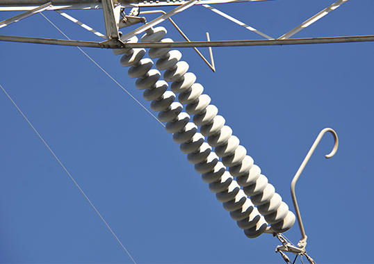
Substations and overhead lines located along the west coast of Sweden can experience high levels of maritime pollution. Two particularly such exposed substations, both built in the 1970s, have been equipped with relatively short porcelain insulators – the only available option at time of construction. To ensure better pollution performance, installation of automated live line washing equipment was deemed a necessity. Although the washing automation was modernized in the late 1980s, the system still did not always function without problems. Sometimes the pollution detection system activated washing more often than needed while at other times it did so too late. There were even cases when the washing system itself initiated insulation flashovers instead of preventing them. As a result, one of the substations eventually decided to wash regularly instead of relying on the pollution detection system to activate it.
Not long ago, these two substations underwent refurbishment and one of the goals was to discontinue application of the costly washing system with its high water consumption. For example, the volume of de-mineralized water needed for each washing amounted to 140 cu. m.
This edited past contribution to INMR by engineers at Swedish TSO, Svenska Kraftnät (Svk), in cooperation with Igor Gutman and Andreas Dernfalk of the Independent Insulation Group, discussed why it was decided to choose application of an RTV-silicone coating in place of washing. It also explained the non-standardized matrix of tests used to select the optimal coating material for the site.
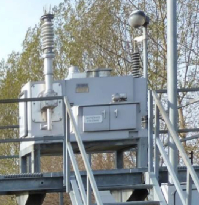
The washing system originally installed at the Ringhals and Barsebäck 400 kV Substations consists of a large tank of de-mineralized water with pump station and piping, a spray system with nozzles and an automated pollution detection system. Spraying procedure in regard to which parts of the switchyard are washed and in what sequence depends on wind speed and direction. The automated pollution detection system relies on a small vertically installed porcelain insulator that collects natural pollution. This insulator periodically rotates 90° and becomes immersed in a water basin. Measurement of pollution is then accessed through conductivity of the water where salt from the insulator surface has dissolved. A threshold conductivity is needed to activate washing. Washing sequence is then determined based on wind speed and direction. There are 20 ramps/sections in the switchyard and, with typical washing time per section of 90 s and given a 30 s pause between different sections, it takes about 40 minutes to complete the washing.

General policy at Svk is now to specify only composite-insulated apparatus at all new substations and this is also valid for refurbishment of existing substations. The main factor behind this policy is the relative safety of composite insulators compared to porcelain in event of failure. Composite insulators also offer excellent pollution performance, which makes them especially suitable for application on the west coast – the only heavily naturally polluted area in the country. This has been confirmed by a series of pollution monitoring investigations as well as the recently created pollution map of Sweden.
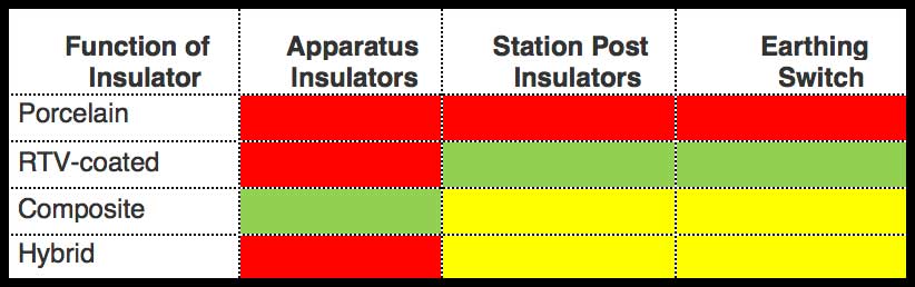
Table 1 shows the different insulator technology options considered when planning the refurbishment and aimed at eliminating need for automated washing. GREEN means the most promising option while RED means an option that is not applicable. Svk has special requirements when it comes to station post (support) insulators as well as earthing switches and prefers not to use composite insulators for these applications due to greater deflection versus porcelain. Moreover, a special Svk requirement for earthing switches is that these must be type tested, which at present is available only for switches equipped with porcelain insulators. As such, the only option to improve pollution performance of these two types of insulators would be coating the porcelain with RTV silicone rubber material. Hybrid insulators that combine a porcelain cylinder with polymeric sheds were also considered however rejected based on these being a relatively new technology with limited service experience.
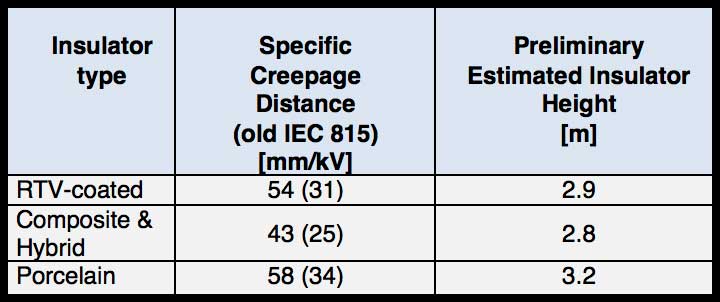
Barsebäck Substation was the first to be refurbished and the process began with a program to establish local site pollution severity. This included compilation and analysis of earlier measurements of main pollution parameters, as prescribed in IEC 60815-1, i.e. soluble/non-soluble parts of pollution (ESDD/NSDD), analysis of service experience and pollution evaluation using directional dust deposit gauges. Based on the data generated, the following preliminary requirements were formulated for specific creepage distance and respective insulation height needed at Barsebäck Substation for each insulation option (see Table 2)
Composite apparatus insulators have now become a proven option at Svk based on highly positive service experience. By contrast, RTV-coatings on porcelain posts and earthing switch insulators still represented a new concept in Sweden. Moreover, there are currently no IEC standards nor even CIGRÉ documents that describe the properties and requirements for RTV-coatings applied on high voltage insulators. The only available such document is an IEEE Guide. While the international community has understood the need for such information and in fact CIGRÉ WG B2.69 has already started to work on this task, most coating applications now being studied involve cap & pin string insulators. As such, Svk had to establish its own methodology to select the optimal RTV-coating to apply to its porcelain support insulators. Preliminary selection in this regard involved identifying available products based on reported service experience and screening these based on small-scale tests.
For reasons of economy, Svk eventually decided to choose only two RTV coating materials to proceed with full-scale testing at 145 kV voltage class. The performance these most promising coatings was then verified through artificial pollution flashover tests and a 1000 h salt fog test conducted on coated porcelain insulators having a profile similar to what would be needed at Barsebäck Substation. The specifics of the application process in each case, relative cost and other practical purchase issues were also considered. Based on results of these tests, it was decided to use these same coatings for all similar Svk projects along Sweden’s west coast.

Evaluating & Testing RTV Silicone Coatings
1. Small-Scale Screening Tests
Based on information in regard to availability and actual service experience, 7 commercially available RTV coating materials were chosen for small-scale screening tests that included:
• an adhesion test according to ISO 2409;
• a hydrophobicity test according to IEC TS 62073;
• a hydrophobicity transfer test according to established principles (see Figs. 3 & 4)
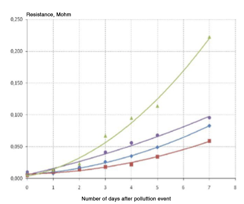
The hydrophobicity transfer property of different coatings was evaluated though a series of leakage current measurements intended to study how hydrophobicity is transferred to the pollution layer that accumulates on the coating surface. This is an important characteristic since the low molecular weight components in the coating material encapsulate salts in the pollution layer, which increases resistance and supresses leakage current to reduce risk of flashover.
Artificial pollution layers were applied on RTV-coated glass plates (according to principles of CIGRÉ TB 555) by pre-conditioning the hydrophobic surface using dry kaolin followed by dipping in a suspension of kaolin, sodium chloride and water. Pollution level was applied according to standard procedures and chosen to be an average value representative of Sweden’s west coast, i.e. SDD/NSDD=0.05/0.1 mg/cm2. Resistance of the pollution layer over time was calculated using applied voltage and leakage current measured between two electrodes on wetted polluted RTV-coated plates. Voltage between electrodes was about 200 V.
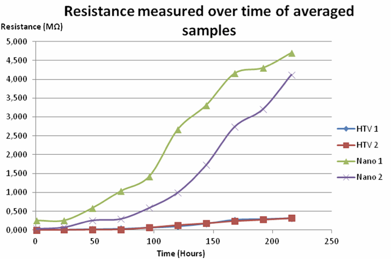
As shown in Fig. 4, there was a significant difference in hydrophobicity transfer property between the different test samples. In fact, this method is highly effective in differentiating the dynamic hydrophobicity properties of a coating material, as also illustrated by similar past test results (see Figs. 5 & 6). Moreover, the method is easier to perform and more decisive than the alternative of measuring contact angle over time and therefore is now being considered within CIGRE.
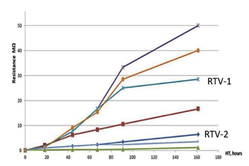
Based on small-scale screening tests as well as reviewing available service experience relevant to Swedish conditions, 2 of these 7 coating materials were finally chosen for further testing. The coating with the higher rate of hydrophobicity recovery was referred to as RTV-1 and that with the lower rate of recovery was called RTV-2 (see Fig. 4) Small-scale tests also confirmed that surface condition as well as humidity and temperature are all important parameters during application of an RTV coating.

2. Full-Scale Tests
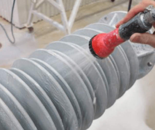
Pollution flashover performance is a key factor in any RTV coating application inasmuch as it governs dimensioning of an insulator under polluted conditions. Since IEC 60507 covers only glass and ceramic insulators, special pre-conditioning was applied according to recommendations in CIGRE TB 555. It was also agreed to test coated insulators after a specific recovery time of about 3 days. Pollution tests were performed on specimens of specially-prepared porcelain and RTV-coated post insulators with total length of about 1 m. The procedure for applying pollution to coated insulators was as follows:
• gentle cleaning;
• pre-conditioning by dry kaolin powder;
• application of the pollution layer by spraying (see 7).
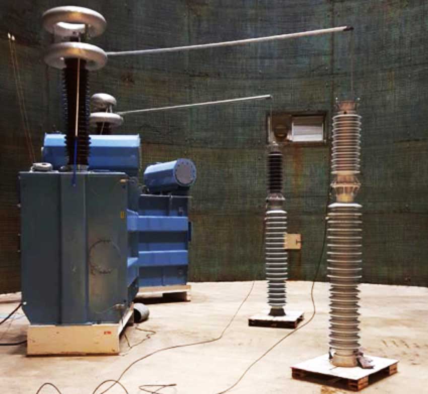
Pollution flashover testing saw the polluted and dried insulators moved into a climate test chamber and placed on porcelain post insulators of approximately 2 m height (see Fig. 8)

These artificial pollution flashover tests were performed using the standard ‘up-and-down’ procedure and showed that coated insulators had significantly higher flashover voltage compared to bare porcelain (by 50%). For example, at a pollution level of SDD=0.06 mg/cm2 (considered representative of site severity at Barsebäck), flashover voltage was more than 40% higher than for uncoated porcelain. Test results were finalized in the form of performance curves versus pollution stress (SDD) for different RTV coatings and uncoated porcelain. These can therefore be used for selecting required insulator lengths at Barsebäck and Ringhals Substations as well as for any other similarly polluted sites in Sweden.
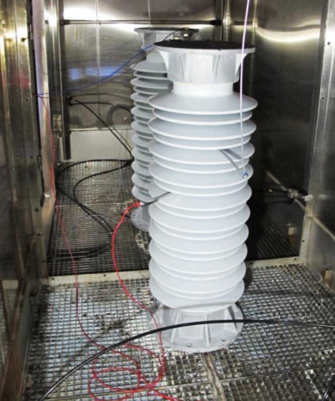
Long-term ageing performance of selected RTV coatings was evaluated using the salt fog 1000 h tracking and erosion test. Since there is currently no standard to evaluate RTV coatings, the tracking and erosion test for composite insulators was selected based on similarity of surfaces (i.e. silicone rubber). As stated in this standard, the 1000 h test is not considered an accelerated ageing test since it does not exactly simulate real service conditions and does not provide acceleration factors to estimate service life. Rather, it relies on continuous stress to detect any potential weaknesses in material or design that could compromise long-term performance. According to the standard, insulators should be tested at a stress corresponding to a unified specific creepage distance (USCD) of 34.6 mm/kV.
Two sections were tested simultaneously by applying voltage in the middle of the insulator (see Fig. 9). Selected test voltage was 20 kV, resulting in actual stresses of 36.4 mm/kV at the upper portion and 34.5 mm/kV at the lower portion. Salinity of the water used for fog generation was 2 kg/m2 in accordance with the standard and also taking into account insulator dimensions (i.e. average diameter).
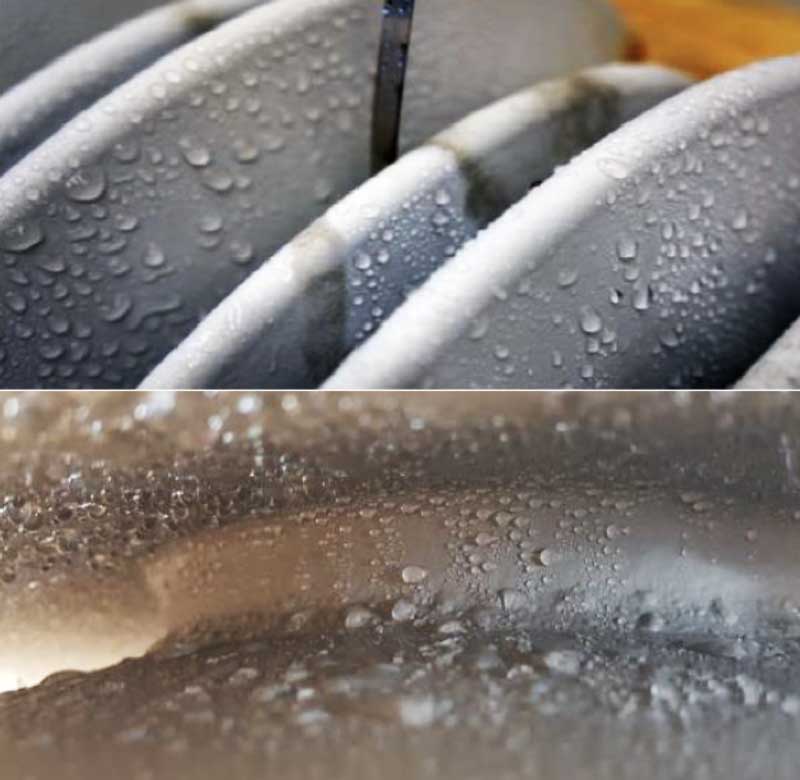
Both pre-selected RTV coatings passed the 1000 h salt fog test. However results were different and in line with the hydrophobicity transfer test results presented in Fig. 4, i.e. the RTV-1 coating with faster hydrophobicity recovery provided better results during the 1000 h test than did the RTV-2 coating. For example, at the end of the test hydrophobicity was HC 1-2 and 3-4 and maximum leakage current was 20 and 240 mA respectively for samples RTV-1 and RTV-2. Insulator RTV-1 was then cleaned using de-ionized water and a new 1000 h test started the next day. After completion of this second test, no signs of deterioration were found and the high level of hydrophobicity was reconfirmed, particularly on the trunk and lower side of sheds (see Fig. 10).

Final Insulator Selection
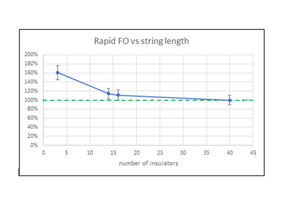
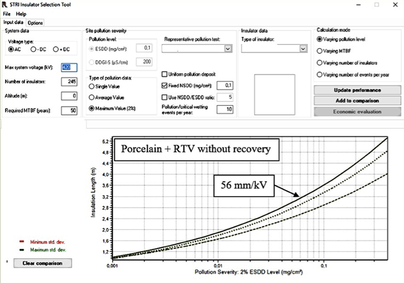
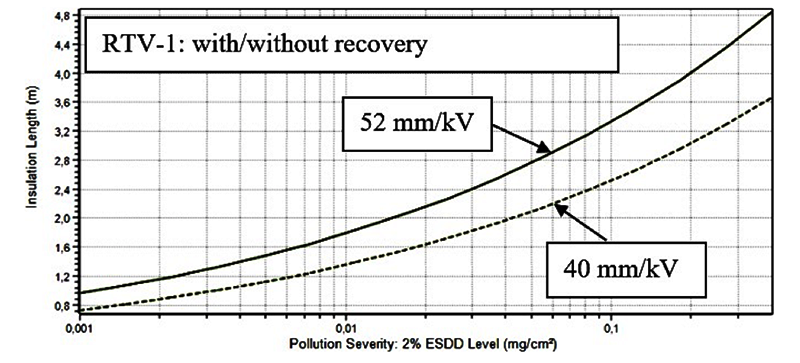
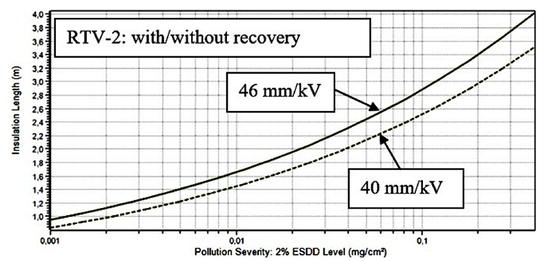
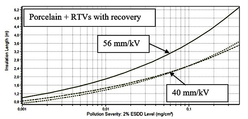
Figs. 11 to 14 present the results of statistical calculations of required insulator creepage length based on pollution test results and performed using Insulation Selection Tool (IST) software that relies on the principle of statistical dimensioning, as prescribed in IEC 60815-1. The criterion was a Mean Time Between Flashover (MTBF) of 50 years. As illustrated in these graphs, uncoated porcelain always requires the longest USCD versus RTV-coated insulators. This is valid even in those situations when RTV-coated insulators have no time for hydrophobicity recovery after exposure to pollution (see Fig. 11). Moreover, it should be noted that RTV-2 (with lower recovery) had better performance compared to RTV-1 (with higher recovery) during the initial stage of testing (i.e. with no simulation of recovery). However, the effect of recovery was significantly higher for RTV-1 than for RTV-2 despite somewhat higher NSDD level (see comparison in Figs. 12 & 13). This observation is in agreement with findings from small-scale tests and salt fog tests. In fact, after a three-day recovery period both RTV-1/RTV-2 coatings have similar characteristics (see Fig. 14).
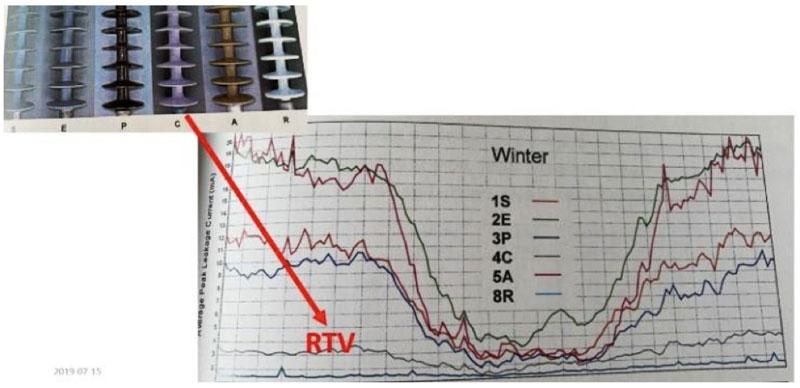
These results are also in line with service observations, presented for example in Fig. 15. These are measurements of leakage currents in very heavily polluted conditions at South Africa’s Koeberg Insulator Pollution Test Station located on the Atlantic coast near Cape Town (i.e. maximum ESDD of about 0.7 mg/cm2). Several insulators of identical profile and length but made of different materials were tested for a year and the RTV-coated insulator showed the second best performance after the semi-conductive glaze insulator.

Conclusions
A comprehensive study of commercial RTV coatings was undertaken with the goal of no longer relying on costly washing at substations exposed to coastal pollution. Since no standard requirements yet exist for these coatings, TSO Svk supported by a research team developed a test matrix to identify the optimal coating material for these conditions. This test matrix included screening tests on low-scale samples which, together with a review of service experience, reduced the originally screened coatings from seven to two. Specifics of application, cost and other practical purchase matters were also considered during final selection.
The two selected RTV coatings were applied on 145 kV insulators and evaluated by short-term pollution tests that allowed selection of proper creepage and insulation length for those insulators of interest. Long-term performance of these RTV coatings was also verified by means of 1000-2000 h tracking and erosion tests. It is interesting to note that test results for hydrophobicity transfer, pollution with hydrophobicity recovery simulation and long-term salt fog tests all proved consistent for RTV-coatings having different rates of hydrophobicity recovery.
Among the lessons learned are that it is a complex challenge for power utilities to distinguish between different commercial coatings and conducting such a study internally is costly. As owner of the substations involved, Svk would prefer to evaluate and select a coating whose basic characteristics and life expectancy can be verified through standardized methods. Hopefully, research driven within CIGRE WG B2.69 will provide minimum such technical requirements for RTV coatings. Based on the above research, four basic tests are regarded as important and should therefore be considered when evaluating an RTV material: an adhesion test; a hydrophobicity transfer test; a pollution test; and a long-term ‘ageing’ test.
References
[1] M. Radosavljevic, T. Lindquist, I. Gutman, A. Dernfalk: “Refurbishment of 400 kV AC substation in polluted environment: pros and cons for different modern insulation options including composite/RTV/hybrid”, CIGRE SC A3 & B3 Joint Colloquium, Nagoya, Japan, 28 September – 2 October 2015, paper 236
[2] IEC 60815-1: “Selection and dimensioning of high-voltage insulators intended for use in polluted conditions – Part 1: Definitions, information and general principles”
[3] M. Radosavljevic, A. Dernfalk, I. Gutman: “Development of requirements for testing and verification of RTV-coated substation support insulators for AC application”, CIGRE-2018, A3-109
[4] ISO 2409: “Paints and varnishes – Cross-cut test”, Ed. 3, 2013
[5] IEC TS 62073: “Guidance on the measurement of hydrophobicity of insulator surfaces”, Ed. 2, 2016
[6] I. Gutman, A. Dernfalk, A. Nefedov, J. Seifert: “Pollution test methods for composite insulators: simulation of coastal environment and recovery of hydrophobicity”, 16th ISH-2009, Cape Town, South Africa, 24-28 August 2009, E-4
[7] I. Gutman, J. Seifert, C. Greyling: “Recovery of Hydrophobicity of a New Nano-composite Coating for Ceramic Insulators”, IEEE ISEI-2012, paper 12, p.p. 48-52
[8] CIGRE Technical Brochure 555 “Artificial Pollution Test for Polymer Insulators”, October 2013
[9] IEC 60507: “Artificial pollution tests on high-voltage ceramic and glass insulators to be used on a.c. systems”, Ed. 3, 2013
[10] IEC 62217 “Polymeric HV insulators for indoor and outdoor use – General definitions, test methods and acceptance criteria”, Edition 2.0, 2012-09
[11] W. Vosloo: “A Comparison of the Performance of High-voltage Insulator Materials in a Severely Polluted Coastal Environment”, Dissertation, University of Stellenbosch, March 2002