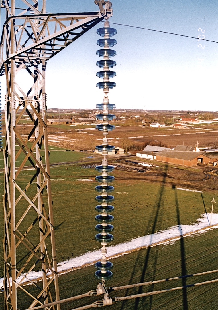
Three proven insulator technologies are deployed in delivery of electrical power. Porcelain and glass insulators have been used since the start and have had a good record of performance and reliability. In fact, rapid expansion of overhead networks would not have been possible were it not for their consistent, long-term insulation and mechanical properties. However, their performance has not always been satisfactory – notably under high pollution applications or in service areas prone to vandalism. In both cases, problems have emerged with the need for costly maintenance involving cleaning or replacement.
Composite insulators were developed about 50 years ago largely because of these deficiencies and introduced on an industrial scale during the 1980s and 90s. While there has been a learning curve as suppliers adjusted their products through successive generations of design based on accumulating service experience, the technology has achieved maturity. In fact, in most countries it is considered equivalent and interchangeable with porcelain and glass. This has been a major achievement if one considers that, as little as 25 years ago, most power engineers knew little about this technology and often regarded composite insulators with distrust.
Today, it is not unusual to find a mix of all three insulator technologies applied on a power system – often on the same line and sometimes even on a single tower. Because line design does not typically change to reflect these situations and since all insulator technologies share common IEC and ANSI standards, some users may believe that ageing and maintenance issues for all insulators should also be the same. However, this is not the case. All similarities between the three technologies end when the insulators are in their new condition. Electrical, mechanical and environmental service stresses can result in significant differences in types and rates of failures.
This past contribution to INMR reviewed these differences, which are often related to materials and methods of manufacture.

Manufacturing Processes
High strength, electrical grade porcelain for line insulators is usually made by the classical wet process. Raw materials – mainly clay, quartz, feldspar and corundum – which can vary in quality, purity and consistency are mixed in water to facilitate blending. The water is then progressively removed in several distinct steps up to firing the porcelain in a kiln where temperature is carefully controlled. A glaze is applied prior to firing, forming a smooth surface and also improving mechanical strength of the porcelain body. Finally, hardware is attached, typically using Portland cement. While porcelain might appear uniform, it is important to note that at the microscopic level it remains heterogeneous, with crystals of various sizes and chemistries having different pores and grain boundaries.
Raw materials for glass insulators include soda ash, feldspar and cullet (pieces of glass from earlier production cycles) as well as minor amounts of other ingredients. These are crushed to form powder and melted in a furnace. The molten glass drops into a mold and is immediately pressed into the desired profile before being subjected to toughening by means of rapid, controlled cooling of the still hot shell. Toughening significantly increases mechanical strength, making the glass shell suitable for high strength cap & pin strings.
Composite insulators consist of a central fiberglass core, polymeric housing and metal end fittings. The core provides the mechanical and electrical strength and is made by pultrusion of unidirectional glass fibers bonded in an epoxy resin. Since this core can degrade in the presence of moisture and electric stress, it has to be protected and this is one of the functions of the external polymeric housing and seals. Housings are expected to resist weathering as well as damage from electrical activity such as corona and surface discharges that can occur under wet, contaminated conditions.
The method of fixing the housing over the core differs among manufacturers. Some mold the complete housing over the rod in sections while others use a combination of a sheath extruded over the core and individually molded sheds that are chemically bonded to the sheath. Seals at the hardware junctions prevent moisture ingress, although some mold the housing directly over the hardware at the critical triple point to perform this function.

Modes of Failure
Each failure mode has specific consequences on service performance of an insulator and the string that contains any failed units. In some cases failure will result in complete loss of service, as in separation of the cap from the pin or breakage of the fiberglass core rod – in both cases with dropped conductors. In other cases, less serious failures might occur such as partial damage to discs or housings or shattering of the glass shell, which most often has no immediate consequence on safety and integrity of the string.
In comparing failure modes of different insulator technologies, it is important to qualify these based on comparing the risks and results of such failures. Below is a summary of principal types of failure, not ranked by order of occurrence or seriousness.
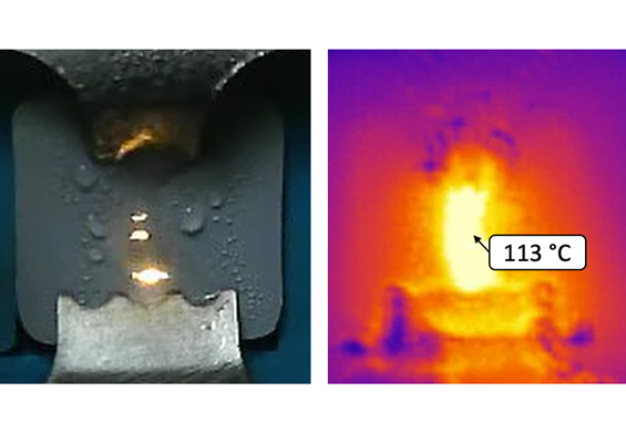
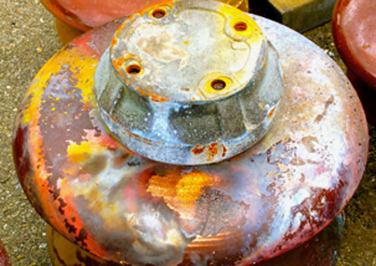
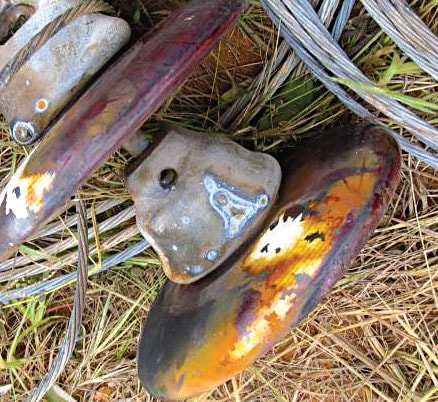
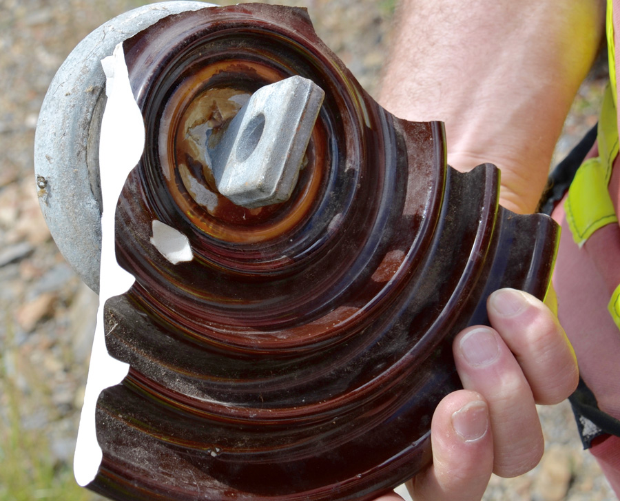
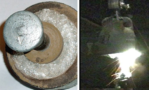
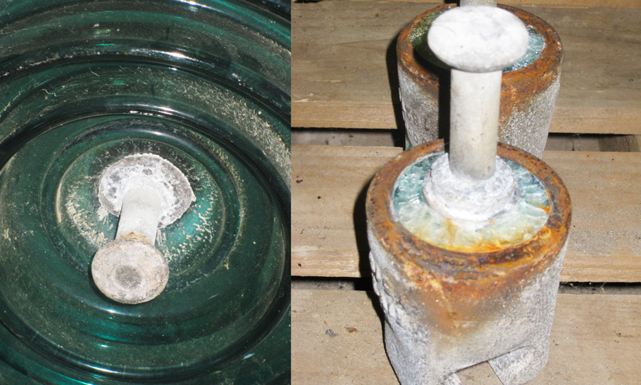
1. Pin Corrosion
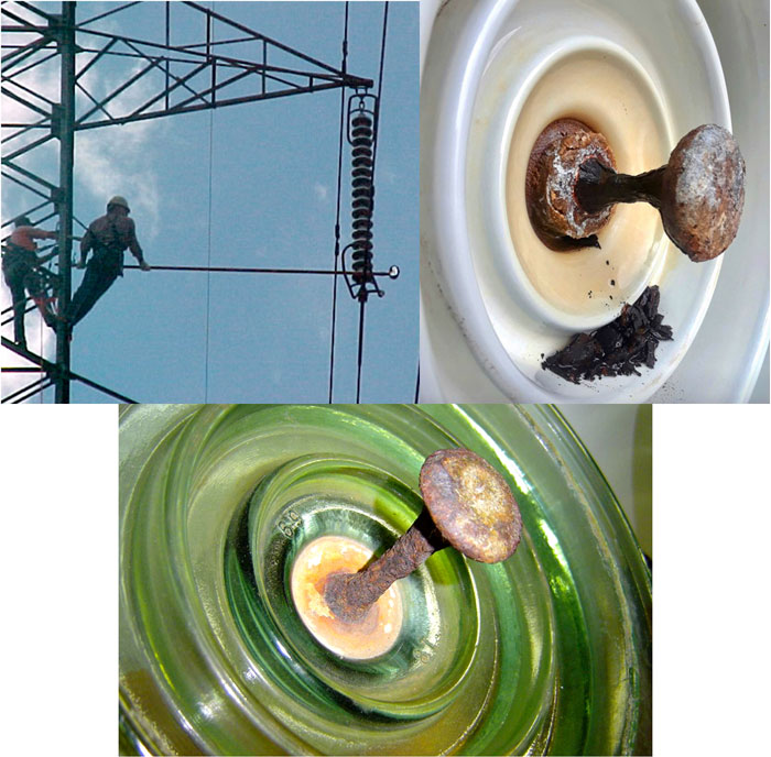
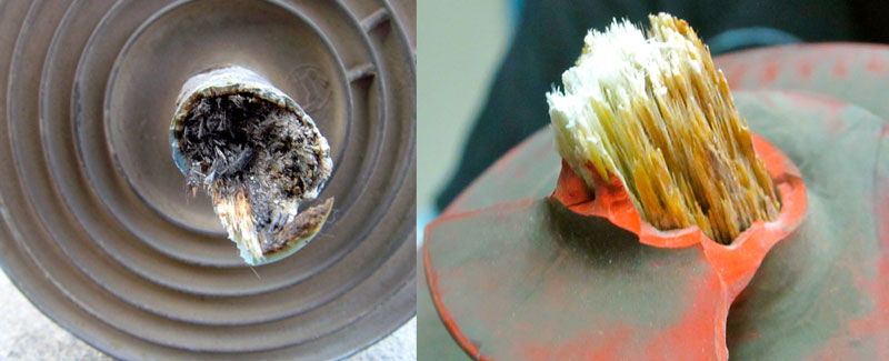
(Top right photo: Courtesy Cristian Gutiérrez).
Problems of pin corrosion occur in places with severe contamination and are basically independent of dielectric bulk material, whether porcelain or glass. In the case of composite insulators, the polymeric long rod between points of different potential limits leakage current to such small values that hardware corrosion is not a serious risk. Application of newer designs with sacrificial zinc sleeves for corrosion protection of ceramic disc insulators is a proven way to avoid onset of this problem, but of course has no impact on ageing of the existing population of discs from earlier generations.
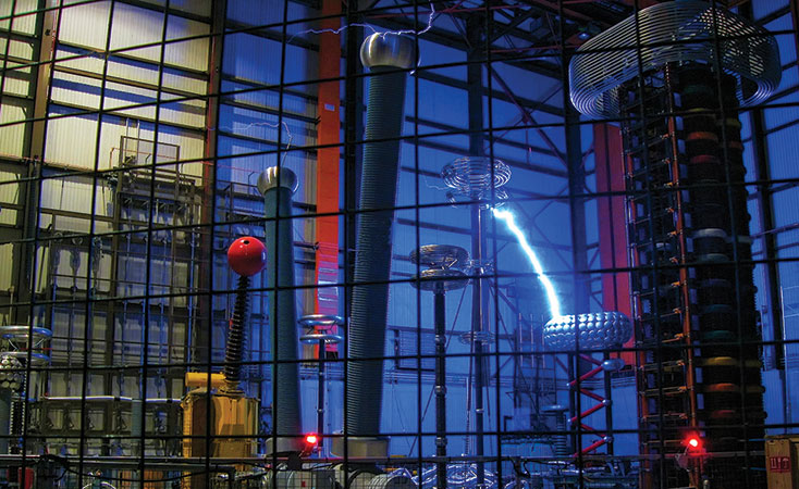
2. External Flashover
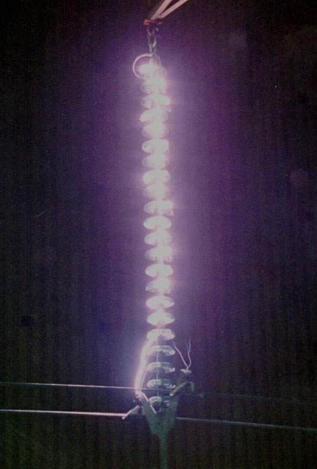
This mode of failure occurs externally to the insulator and results in a temporary loss of insulation strength. Its occurrence depends mainly on pollution conditions and lightning activity as related to key design parameters of the string, i.e. leakage and dry arc distances, as well as the system’s insulation coordination. For any given leakage distance, flashover is a more common problem for porcelain and glass insulators due to their relatively easy wettability compared to composite insulators that utilize low surface energy housings which resist water filming.
Comparing porcelain and glass insulators of any given leakage distance, shed profile and string design parameters, there have been no significant differences in reported rates of external flashover failure. The power arc current typically causes the glaze in the porcelain units in contact with the arc to melt leaving behind a rough surface, more susceptible to pollution accumulation and eventual failure.
Composite insulators are more resistant to power arcs with only superficial burning and/or ablation of the housing observed. While some melting of the hardware may occur, there is generally no internal damage.

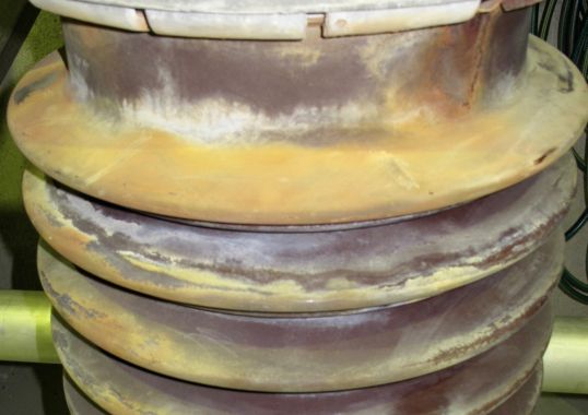
3. Internal Puncture
This failure mode is seen in porcelain insulators and relates primarily to problems with raw materials and production processes. Some manufacturers have inferior quality control methods and this impacts not only macroscopic properties such as color but also microstructure of the porcelain body itself.
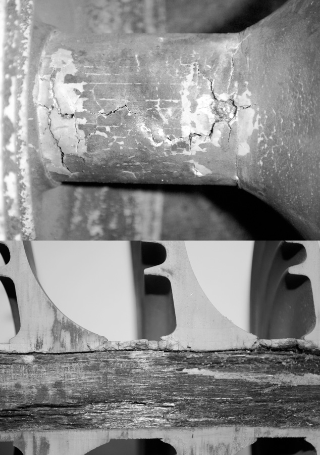
The images below show the microstructure of insulators that have passed all relevant tests in their new condition. While the presence of pores or voids and many grain boundaries between crystals are common to all porcelain, sometimes micro-cracks can also exist. These can grow under the multiple stresses generated by service conditions and eventually lead to electrical breakdown through the bulk dielectric.
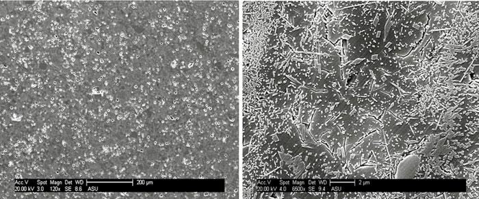
Such internal punctures of porcelain insulators are detectable only with a close-up inspection of the line using measuring instruments. Reliable statistics for this type of failure are therefore not available on a global basis. Experience at many power supply companies shows that this problem, while generally rare in new insulators, is more common on older lines, especially if the porcelain insulators were not of high quality.
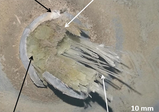
Composite insulators are normally not at risk of puncture since the electrodes of different potential are separated by a long fiberglass rod. However, punctures in the form of holes or cracks in the housing can occur under certain conditions, such as exposure to corona discharges, and these can provide an access for moisture to the rod. Tracking along the rod under the housing material has then been known to occur, resulting in permanent loss of electrical strength – just as in a puncture.
If the internal tracking is considerable, the insulator will not be able to support the electrical stress and the rod will essentially become carbonized along its entire length. This mode of failure is sometimes referred to a ‘flashunder’ and can also result from damage to the housing’s integrity from mishandling during transport or installation.
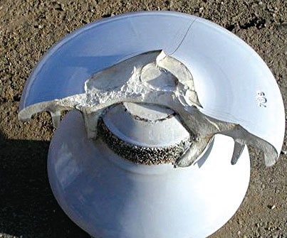
Puncture of toughened glass insulators is seldom seen in service. The increased strength from the toughening process derives from opposing balanced tensile stresses induced inside the glass body and compressive stresses throughout the outer surface. As a result, such a glass shell can only either shatter completely or remain intact. Moreover, since glass is essentially a cooled liquid, there are no interfaces within the dielectric. The toughened shell is immune from hidden internal micro-cracks or punctures that would cause the disc to shatter. It therefore tends to breaks in a predictable pattern.
While it is possible to puncture the dielectric in the laboratory with very high electric stresses, such stresses are not common in service. Even when the shell is broken, the external air insulation of the stub breaks down before the electric stress can rise to higher values, thus eliminating dielectric puncture. Even in case of flashover of the string, the arc will always be external to the stub since its internal impedance is significantly higher than that of the air gap between the cap and pin electrodes.
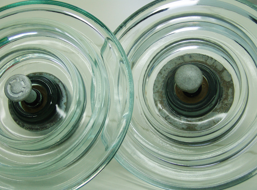
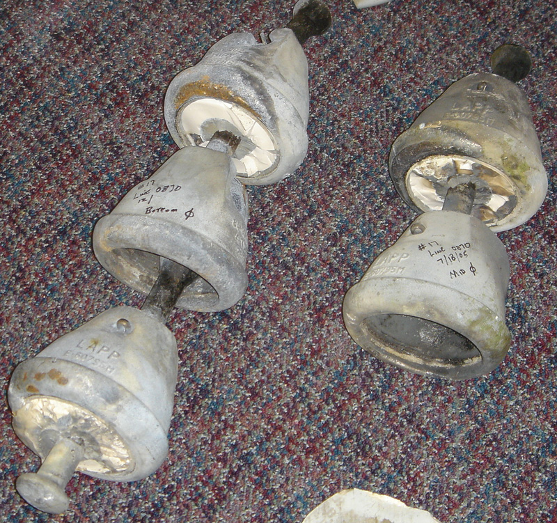
4. Mechanical Separation
Such a mode of failure is rare but not impossible in the case of toughened glass insulators. Operating data reported by utilities suggests that their failure rate over the last 50 years is extremely low – on the order of only 1 in 10 million. This problem is generally associated with exceptional events such as repeated power arcs melting the fittings or uncontrolled vibration of phase conductors propagating to the insulator strings and leading to fatigue breakage of the pin.
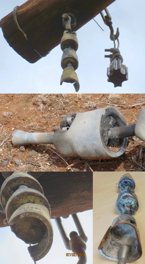
By contrast, service experience from many power utilities indicates that the separation of strings of porcelain insulators, sometimes referred to as ‘de-capping’, is far more common. This is largely associated with time-related ageing, leading to cracks and puncture of porcelain shells under continuous electrical and thermo-mechanical stresses. Separation of cap and pin occurs when the string flashes over, e.g. triggered by voltage surges from lightning or switching events or by pollution. The power follow current can produce such large electromechanical forces in the punctured units as to cause the porcelain to separate from the cap and result in a line drop.
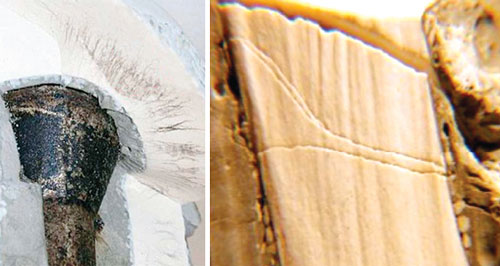
Brittle fracture of composite insulators leads to mechanical separation of the fiberglass rod, also causing the conductor to drop. This failure mode was initially reported in some first generation insulators manufactured in the 1970s and attributed to attack on the rod by nitric acid produced by corona in a moist environment. The exact source of the acid later became a topic of much research and debate.
While there is sufficient proof that electrical stress is not required for brittle fracture to occur, it can nevertheless accelerate the process. There is also evidence that certain types of chemicals used in manufacturing fiberglass can themselves produce acids, even without moisture from the outside. Still, it is commonly accepted that effective sealing of the rod from the elements and the use of corrosion resistant rods is the best way to minimize this type of failure. In the end, it is widely believed that brittle fracture can be due to a variety of factors and not easily explained by any one mechanism alone.
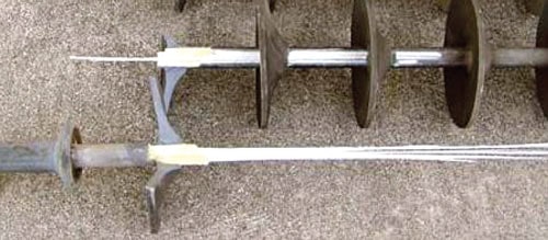
Research in China linked this failure mode to production deficiencies such as
improper bonding of housing to core rod.
5. Partial Breakage/Damage in Dielectric Material
This type of failure is most evident in porcelain insulators and typically caused by vandalism or poor handling during storage and installation. Unlike toughened glass insulators, only a section of the porcelain disc is broken and any additional internal cracking cannot be easily ascertained.
Cases of damage to composite insulators by bird pecking have been reported and can vary from small tears in the sheds to their complete removal and exposure of the core. Most such incidents have occurred on new insulators, shortly after installation but before energization of the line. Recent evidence suggests that energizing the insulators does not eliminate all risk of such damage.

6. Shattering of Dielectric Shell
This type of failure applies only to glass disc insulators and is due to the instantaneous release of the internal stresses induced in the shell during the toughening process. Vandalism by bullets or stones is the main cause and one of the reasons why power supply companies experiencing such problems have shifted to composite insulators.
Sometimes this same failure occurs without any external agent and is referred to as ‘self or spontaneous shattering’. This phenomenon is specific to toughened glass and can be induced by poor quality control, evident in the presence of inclusions or impurities in the tensile zone of the glass body. Inclusions are hard particles that have not fully melted in the furnace, typically from the refractory bricks or un-melted raw materials. Average size of such particles is less than 100 microns and therefore they are not visible to the eye nor is there a practical method to detect them. The most effective way to screen out toughened glass shells containing such inclusions is by application of specific thermal shocks to each glass shell prior to assembly of fittings. A thermal shock test is intended to weed out and destroy glass shells containing inclusions.
Even though thermal shock testing is carried out twice during production, a very low probability exists that some glass shells containing inclusions may survive this quality control and shatter during early years of service on the line. This self-shattering can be triggered by a variety of external factors or might occur without any special circumstances. It has therefore been termed ‘spontaneous shattering’.
Statistics obtained over the last 20 years reveal typical rates of spontaneous shattering on the order of 1 per 10,000 units per year or less, depending on manufacturer. Cases have been reported where spontaneous shattering of glass discs have occurred on DC lines in a high pollution environment due to leakage current warming up the cement inside the fitting, causing it to expand slightly. The solution in such unusual cases was to apply RTV silicone coatings onto the discs to limit surface activity.
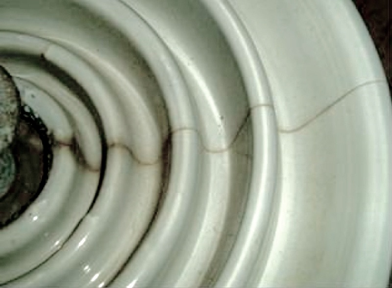
7. Radial Cracking
This type of failure has been attributed to cement grout phenomenon and applies only to porcelain insulators that were assembled using overly expansive Portland cement. Such radial cracking of porcelain disks can eventually result in internal puncture. There are no reliable statistics regarding the incidence of this type of failure but it is widely published that failure rates of porcelain insulators due to cement growth problems are generally associated with specific production batches. In North America, for example, large populations of porcelain insulators manufactured in the 1970s were affected by this problem.

Mechanical Strength of Aged Porcelain & Glass Insulators
The primary function of insulators is mechanical, namely holding the line above ground. Users of insulators are therefore especially concerned if this property has been compromised because of defects or ageing in service. Condition assessment is therefore critical so that proper maintenance and replacement can be carried out before a failure occurs. A past study was conducted involving the residual mechanical strength of more than 100 porcelain and toughened glass insulators in service for periods ranging from 20 to 70 years. The porcelain insulators were evaluated as received. About half of the glass insulators were evaluated as complete units while the remainder as stubs (after the shell was broken in the laboratory using a hammer).
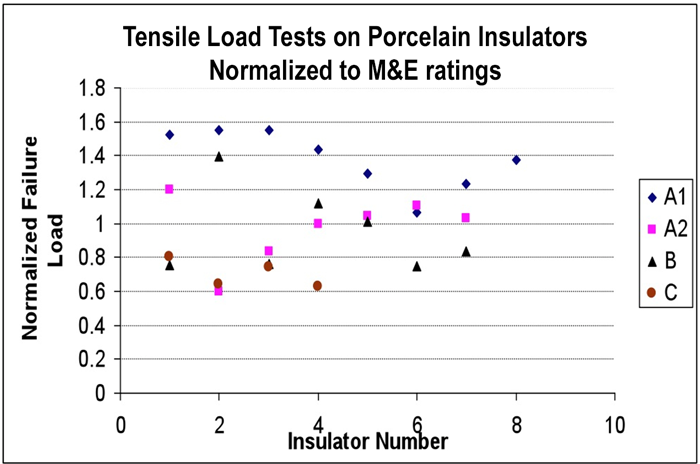
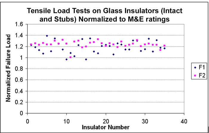
From charts of tensile failure loads normalized to that of the insulator’s M&E rating, it was evident that porcelain insulators showed large variation in mechanical strength among field-aged units. In fact, a reduction of up to 40% was seen for some manufacturer’s products. Superior quality units exhibited much higher load to failure. Data for glass insulators, by contrast, showed a smaller spread in failing load and there was no apparent difference in this respect between complete glass insulators and stubs.
Summary & Conclusions
It is usually more important to focus on mode of insulator failure and impact on power utility operations than on failure rates alone. This is because failure rate can depend on voltage class of the line. Users tend to specify only well proven products on critical transmission lines and are more willing to experiment with potential new suppliers when it comes to lower voltage lines.
In the case where failure rate is defined as ‘mechanical separation of the string’, service experience clearly indicates that toughened glass insulator strings are significantly less prone to separation compared to strings of porcelain or composite insulators.
Failures that involve puncture of the dielectric body can be quite common for older porcelain insulators but are typically absent from toughened glass insulators and rare in the case of composite insulators. Punctured discs cannot be identified from the ground and require additional testing equipment. Moreover, unless the puncture results in a short circuit, it is not easily detectable.
Failures associated with cement growth problems (and consequent radial cracking) have been reported only on porcelain insulators and specifically due to use of improper cement. These problems are hard to detect in the initial stages.
Risk of pin corrosion in areas of high pollution is a problem potentially affecting large populations of glass and porcelain disc insulators of older designs, before adoption of a sacrificial zinc sleeve countermeasure. When dealing with problems of vandalism and self-shattering rates of toughened glass insulators, it is important to consider that the glass stub remains electrically not punctured and the overall mechanical integrity of the insulator is retained as well. Strings with missing glass shell are also easily observed from the ground, although in countries with high vandalism, this can mean high maintenance costs. With regard to electrical performance, while a glass stub will have lost external insulating function, it will keep a possible arc in the air and outside the metal fittings with no risk of pin ejection and mechanical separation.
The organic nature of materials used for composite insulators gives rise to potential failure modes that are unique compared to ceramic insulators of porcelain or glass. For example, tracking and erosion of the housing material from surface discharges, pecking by birds, tracking of the fiber glass core and brittle fracture are all potential modes of failure. Still, in spite of the increased number of failure modes possible, composite insulators have improved significantly over the decades. Today, well designed and properly manufactured units offer excellent proven service performance, even under demanding service conditions, combined with very low rates of failure.