Ceramic insulators installed on power grids have been subjected to widely varying temperatures for decades. But as climate change accelerates, the severity of weather patterns, droughts and wildfires is increasing and exposing lines and their insulators to growing environmental stresses. Fires on a forest floor, for example, can produce temperatures of 800°C while raging fires at treetop height can reach 1200°C. In addition, lightning strikes and flashovers can cause power arcs with temperatures as high as 19,000°C.
Moderately elevated temperatures can be caused by proximity to fires, electrostatic precipitators and induced magnetic fields or even by simply exceeding a line’s current ratings. Operating conditions of a utility also play a role since conductors can attain elevated temperatures during line over currents. Inductors and coils can induce magnetic fields that heat metal parts to from 150°C to 200°C.
Insulators are designed to operate within the normal temperature ranges of the equipment they support. It is therefore not expected that they withstand extreme elevated temperatures without damage, i.e. mechanical and dielectric strength can be reduced depending on event and temperature. Utility equipment will therefore need to be inspected for possible damage and urgency for maintenance or replacement. While insulators that sustain severe damage are typically easy to detect, those with less noticeable damage can sometimes go undetected.
This edited past contribution to INMR by Patrick Maloney of PPC Insulators discussed the effects of elevated temperature on ceramic insulators as well as relevant points to consider. Construction design and how heat is applied all play a role.

Materials
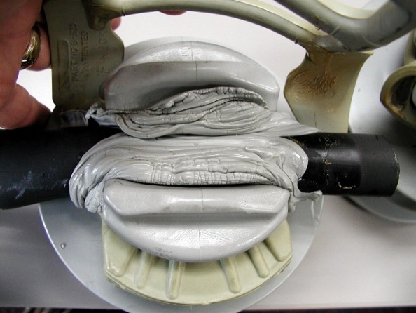
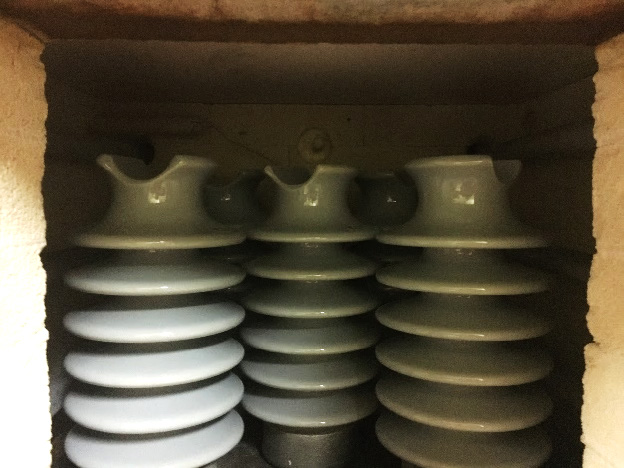
Although pin, spool and strain insulators are made solely of ceramic material, most porcelain insulators consist of a combination of materials, including the ceramic insulation, fixing metal parts, bonding cement and expansion coatings. Each material responds to heat in different modes. The ceramic material and iron fittings can withstand temperatures well above normal operating conditions. For example, ceramics can be re-fired at temperatures reaching 1300°C for repairing glaze before assembly. Cast iron can withstand 650°C, as per ASTM A278-53, and hot-dipped galvanizing will melt at 419°C. More limiting materials include the portland cement and the bituminous asphalt used for expansion joints. Bitumen begins to melt at 115.5°C (e.g. PPC Insulators uses 75°C.) At this point, the bitumen will lose mechanical strength and could potentially liquefy and run out of the hardware. Portland cement can lose mechanical strength due to factors such as temperature level, heat rate, duration, type of aggregate, solo vs. cyclic thermal event and whether or not the cement is confined.

Construction
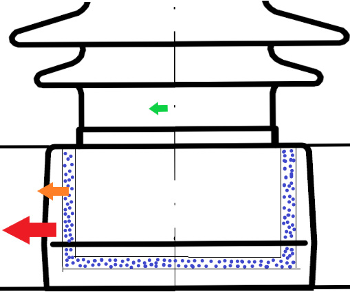
An insulator’s design contributes to how it is affected by heat. In the case where insulators consist of metal fittings and a ceramic body, fittings are attached using Portland cement. Modern ceramic station post insulators are constructed with metal fittings external to the porcelain whereas cap & pin post insulators of the past were constructed with the mounting pin internal to the porcelain. Thermal expansion will affect each differently.
Thermal Expansion
The key components of a ceramic insulator, namely the ceramic insulating body, the metal fixing fittings and the Portland cement all have different coefficients of thermal expansion:
Iron: 11.5
Portland cement: 10.0
Porcelain: 5.7
Shape also influences how an object will expand under heated conditions. A thin rod, for example, will expand far more in length than in diameter. Similarly, a thin-walled tube will gain circumference and thus diameter. A thick-walled tube will experience expansion in circumference and wall thickness.
Insulators with external metal hardware will not induce compressive forces under elevated heat. The thermal expansion of metal fittings is greater than that of Portland cement and porcelain. Moreover, the Portland cement’s expansion is greater than of the porcelain. In a reverse scenario, where an insulator has internal fittings, the cement would be under high compressive forces resulting in possible damage to the structure.

Heat Exposure Modes
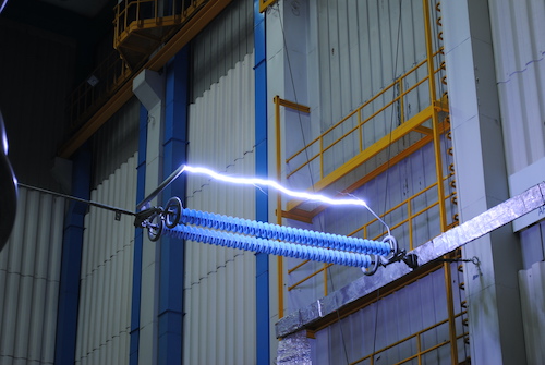
There are varying conditions under which an insulator can become exposed to heat. In the case of fire or an arc flash, the heat is applied at a high rate followed by a natural cooling cycle. The heat source could be unbalanced, e.g. in the case of an arc flash that causes sheds to crack and glaze to melt. Arc flash events produce very high temperatures but have very short duration. Long duration heat sources are those that occur over many hours or days and where the entire insulator location remains at the same temperature. Elevated temperatures can be from a single event or cycled over time.
Analysis After Elevated Heat Exposure
Extreme Heat
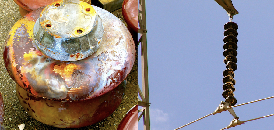
In the case of a power arc flash, damage can be clearly seen due to the extreme heat of 19,000°C. The glaze can become darkened and blistered. Events with arc durations that exceed normal protection equipment’s clearing/interruption time of 5 -16 ms can cause some sheds to shatter. This is due to the isolated heating causing thermal expansion at the thin area of the sheds.
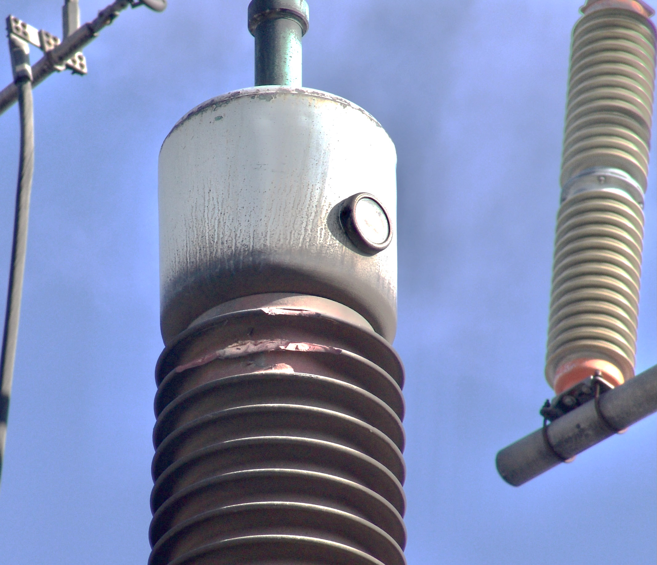
Ceramic station posts are made of high-density materials and are slow to heat. Most of the damage will be external for easy visual evaluation. Blistered glaze has a rough surface that will collect contamination over time. Sheds lost to shattering will also reduce creepage distance. Still, exposed unglazed ceramic areas are not affected by water ingress due to the lack of porosity of well-fired ceramic materials. Blistered glaze or missing shed conditions is not an immediate concern if the damage is limited to less than 10% of the surface and does not extend to the core of the unit. Insulators with such damage can be replaced whenever convenient.

Moderate Heat Exposure
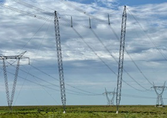
Historically, overhead lines have shown a low threshold for heat exposure. For example, heated conductors will sag more, creating clearance issues. Aluminum can be annealed, losing strength. Overhead conductors such as ACSR, AAC and AAAC have a maximum operating temperature of 100°C. More modern conductor options including ACCR, ZTACIR and ACCC, have much higher temperature ratings, i.e. 180°C to 250°C. At such high temperatures, polymeric insulators become vulnerable to damage.
Analyzing ceramic insulators exposed to more moderate temperatures of 100°C above normal design limits can pose challenges. A typical temperature limit for equipment in a substation would be 105°C and 65°C above a 40°C ambient baseline. Moderate heat exposures can be caused by over currents, proximity to electromagnetic fields, substation fires or nearby wildfires.
With exposure from moderate to high elevated temperatures, the focus shifts to the cement. Ceramic and iron materials can withstand 200°C indefinitely but Portland cement will lose strength given prolonged exposure to 100°C or higher. Several variables and combinations of conditions will influence level of degradation.
The goal of this research was to investigate realistic elevated temperatures that might or might not cause catastrophic failures soon after an event. A cap of 400°C was defined as the upper end. Note that 400°C is approximately four times the typical temperature limit for insulators. With the Portland cement identified as the critical material, thermal testing was needed to better understand the rate at which strength is lost. Testing was performed on assembled insulators, i.e. with cement and metal fittings.

Test Approach & Summary
Tests were conducted to determine the temperature exposure and duration at which cantilever strength is reduced. The first steps were exploratory in order to establish the region or range at which changes in cantilever strength might be observed. For example, past such studies have shown that insulators exposed to 200°C for 4 hours exhibited little reduction in cantilever strength. Here, the testing began at 300°C and increased or decreased to a find a threshold temperature. Temperatures above 400°C were deemed beyond the scope of this study.
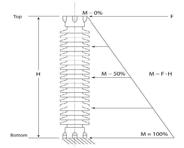
Groups of 5 insulators were exposed to different temperature cycles, with a maximum of 400°C. Initial duration of heat exposure was set as 4 hours. The samples were then subjected to cantilever testing per ANSI C29.1 Clause 5.1.3 in order to determine strength loss compared to the control group. The insulator samples selected for study were ANSI C29.7, 57-2 line posts with heights of 305 mm, diameters of 146 mm and a cantilever rating of 12.5 kN.
The lab oven, measuring approx. 500 mm by 500 mm and with height of 460 mm, has a maximum heat capability of 1200°C. Five samples were placed inside for each experiment.
The bending equipment met the required force of 18 kN and was capable of a center mount stud utilizing a ¾-10 UNC oversized thread. This equipment could apply a precise load rate within the bounds of ANSI standard C29.1. The load was applied rapidly up to 75% of rated cantilever strength, i.e. 9.3 kN. The remaining load was applied at a rate of 45% of rated cantilever/min, until yield.
Ten insulators were subjected to cantilever yield levels to establish a control group. Each temperature exposure test group consisted of 5 samples.
Expected cantilever strength reduction for the 4-hour exposure would likely fall between 150°C and 400°C. The first round of heat exposure testing was at 300°C for 4 hours. Once cooled to room temperature, each set was tested to cantilever yield level within 24 hours. The data was then reviewed to determine temperature levels for subsequent testing.
The expected cantilever strength reduction for the 12-hour exposure would fall between 200°C and 400° C. The first round of heat exposure tests was at 300°C. Again, each sample lot consisted of 5 units. Once cooled to room temperature, each set was tested to cantilever yield level. Data was reviewed to determine temperature levels for additional tests.

Test Findings & Discussion
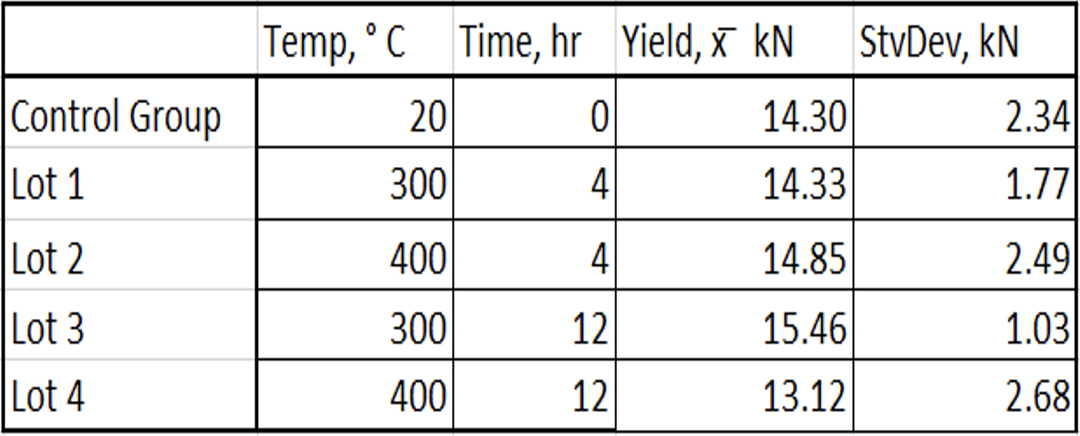
Average cantilever strength of the control group was measured at 14.30 kN, with standard deviation of 2.34 kN.
The first group of insulators was exposed to 300°C for 4 hours. average cantilever strength was measured at 14.33 kN, with standard deviation of 1.77 kN. The second group was exposed to 400°C for 4 hours. Now, average cantilever strength was measured at 14.85 kN, with standard deviation calculated at 2.49 kN. The third group saw the test duration increased to the upper limit of 12 hours. Temperature level was 300°C and average cantilever was found to be 15.46 kN, with standard deviation at 1.03 kN.
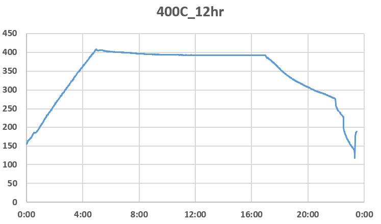
The test of the final group involved maximum temperature of 400°C and longest duration, at 12 hours. Average cantilever strength was found to be 13.12 kN – a decrease of 8% compared to the control group. Standard deviation of findings increased to 2.68 kN.
Conclusions
Ceramic insulators are typically rated for 105°C. Power arcs and direct exposure to wildfires will almost certainly destroy all equipment. By contrast, moderate to extreme conditions such as found in proximity to wildfires, near substation fires and from over currents can also subject insulators to temperatures well above their ratings. While some damage may occur, the insulators can remain in service pending further analysis.
This research has demonstrated that ceramic insulators are robust and resilient to moderate elevated temperature exposure. Future studies in this area are planned to also include cycle bending loads.