There has been a steady increase in application of composite station posts worldwide and one country following this trend has been Sweden. Although experience has demonstrated that high electric field on a composite insulator can accelerate ageing, most of the 1000 station posts installed in that country were not equipped with protective grading devices. Moreover, no other special requirements were issued during the procurement process. Since that time, a significant number have shown signs of deterioration and even internal damage.
This edited contribution to INMR comes from Peter Sidenvall at the Independent Insulation Group, in co-operation with engineers at Swedish TSO Svenska kraftnät as well as Norconsult. They review work to inspect and assess the condition of these composite station posts as part of a planned replacement and remediation project.
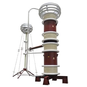
Svenska kraftnät (Svk) operates about 200 substations at 220 and 400 kV. The majority of these were built decades ago and, given the energy transition, many are planned to be refurbished or rebuilt.
Over the past 20 years, for reasons of safety, it has been Svk’s policy that only composite insulators be applied for all apparatus insulation at substations. Moreover, during one 7-year period, there was also the requirement to use only composite station post insulators, but with no criteria specified in terms of field grading or polymeric housing material.
Due to this policy, more than 1000 composite station post insulators were installed across some 30 substations, and most were not equipped with grading rings. Since that time, a significant number have begun to show signs of deterioration and some cases internal damage.
A project was therefore initiated to convert all station post insulators back to porcelain equivalents or to employ other countermeasures if this was not feasible. The work included inspecting the installed fleet of composite station post insulators to assess their status during the transition and to prioritize the exchange process.
Inspection Program
Field inspections were conducted on annual basis at 400 kV substations and once every two years at 220 kV substations. Most were performed during the months of Sept. to Nov and Feb. to April to avoid heating from the sun as well as insulators covered by snow and ice. Inspections were scheduled, as much as possible, to be conducted during cloudy weather with no precipitation. Classification of any visual defects observed was then made based on the CIGRE, STRI and EPRI Guides, although none were strictly followed.
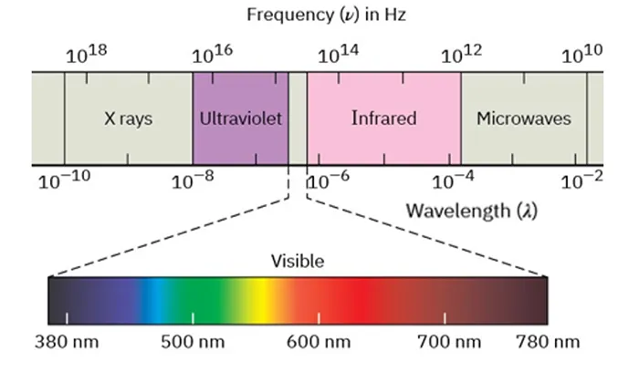
The three inspections technologies utilized, i.e. visual, infrared and ultraviolet, operate in different regions of the spectrum (see Fig. 1) and provide extensive information within their respective spectra. For all, it is important to have large, sensitive sensors and lenses with long focal length due to the relatively large distance between camera and the insulators being assessed.

A. Visual
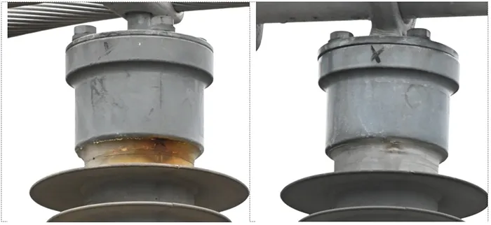
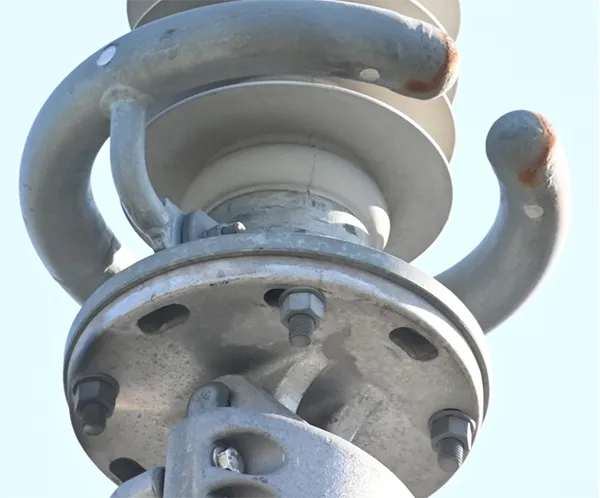
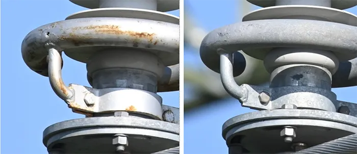
Visual inspection reveals changes in appearance, such as biological growths that could lead to localized loss of hydrophobicity, as well as defects due to insufficient quality control during production or from damage during transport and installation. Also revealed would be instances of corrosion and indications of electrical activity in the vicinity of end fittings. Where there has been internal damage, traces of electrical activity can also be seen along the insulator. In the worst case, punctures or cracks can be seen (see Figs. 2 & 3).
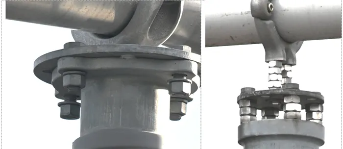
Moreover, visual inspection revealed examples of inadequate quality control during manufacture and/or installation (see Figs. 5 & 6). While not specifically related to composite insulator technology, these were nonetheless deemed important in the overall assessment.

B. IR
Infrared inspection reveals presence of heat on the surface of an insulator. If the weather is cloudy and the insulator has been properly dimensioned, it should show a homogeneous temperature profile along its entire length. Still, in many cases there may be evidence of a slight temperature rise near end fittings due to one or more of the following:
• Reflection and/or radiation from busbars or nearby structures;
• Dielectric losses in housing material due to high electric field (this will be more significant under humid conditions);
• Heating from continuous corona activity from end fitting, if poorly field graded;
• Dry bands and discharge activity from pollution.
Inspection during sunny weather can prove difficult to interpret since heat from internal damage can be masked by significant heating (e.g. tens of °C) from the sun. Moreover, during sunny conditions, internal damage may not be fully active since it will be dry. It is therefore recommended to inspect insulators from their shaded side.
Dielectric losses can reach slightly less than 10°C in extreme cases, although these are normally only a few °C. Corona activity from the end fitting towards the housing can reach up to 5°C while water induced corona on the surface of the housing causes only slight heating (generally below 1°C). Dry band activity along the surface can heat the housing by as much as 20°C.
It is important to note that heat transfer is typically slow since a good insulator from the dielectric perspective is often also a good insulator from a thermal perspective. As such, an internal heat source may not appear as hot on the housing surface as the extent of damage might warrant. Nonetheless, an internal defect close to the housing, observed from the side of the inspector, will generally show more than 5°C of heating and in extreme cases even up to 100°C.
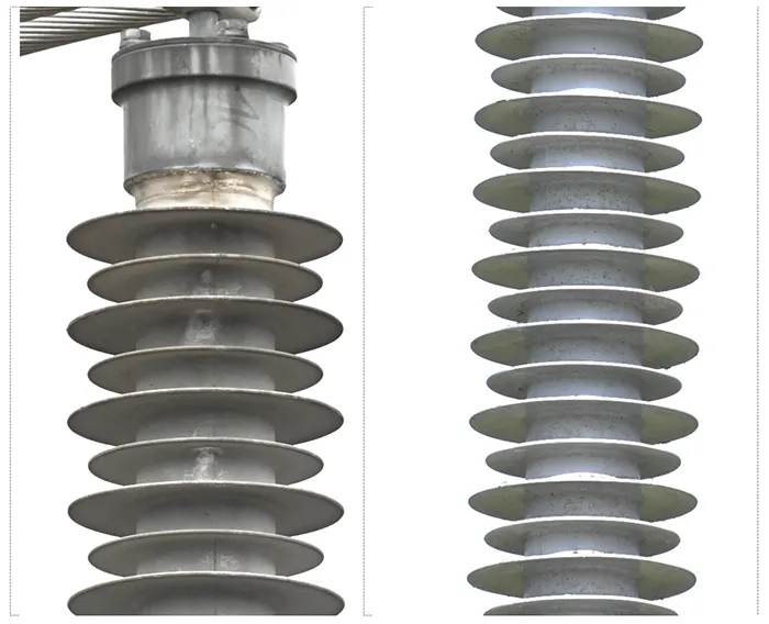
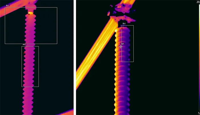
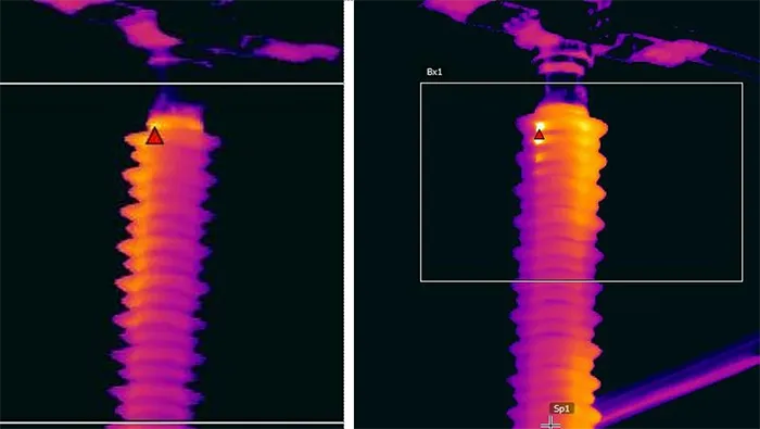
Moreover, internal heat may not show up equally on all sides of an insulator, especially so for large diameter station posts, as shown in Figs. 8 and 9. It is also important to emphasize that absolute heating is not always relevant to deteriming the severity of any case of internal damage. Location of heating can sometimes be more important in providing relevant information about what proportion of a long insulator has been compromised.
It should also be noted that wind and precipitation exert a powerful cooling effect on insulator surfaces. Taken together with the low heat transfer of insulating materials, it may not always be possible to detect internal defects under such conditions. Thus, it is necessary to take note of even slight changes in temperature, e.g. less than 1°C. Given this, it becomes easy to understand the importance of keeping temperature gradient within a narrow band.

C. UV
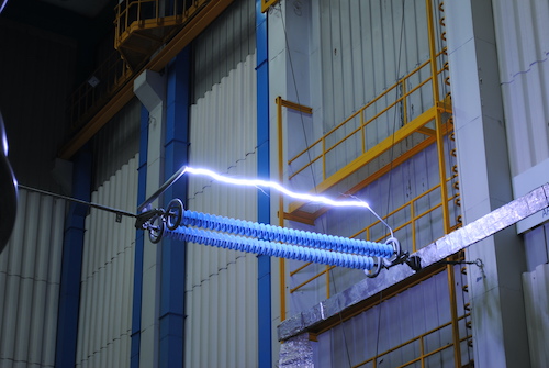
UV inspection reveals poor electric field grading and pinpoints sources of corona. Typically, these might be items such as bolts or sharp edges. But in the case of 400 kV insulators without protective grading continuous corona activity can be expected from the end fitting. Moreover, this will indicate if there has been internal damage that could lead to a conductive path and a change in electric field distribution along the insulator.
If the electric field exceeds the electrical withstand strength of air (approx. 2.4 kVRMS/mm), discharges will be initiated. Discharges appearing somewhere along the surface away from the end fitting suggest that electric field grading has been affected by a conductive layer. Figs. 10 & 11 provide examples of findings from UV inspection.
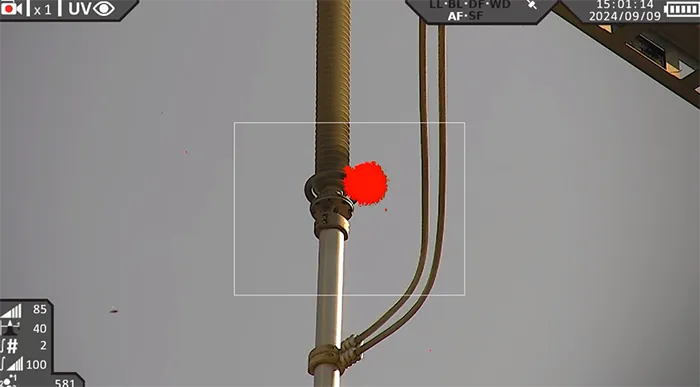
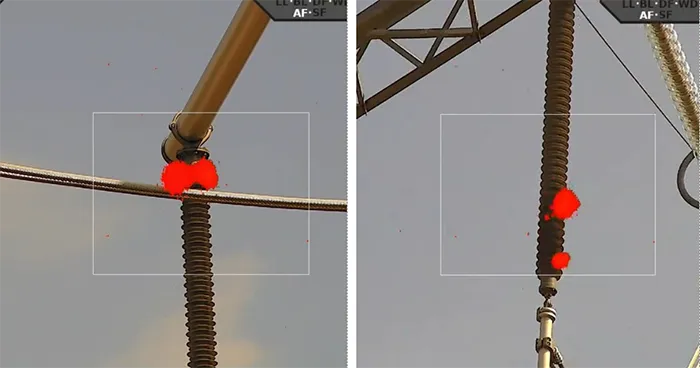
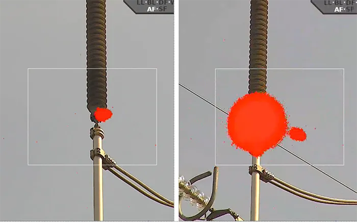
Daylight UV-cameras only detect discharges directed towards the lens, while any defect positioned on the opposite side of the insulator will not be detected. Therefore, discharge counter threshold serves little purpose due to lack of knowing whether all serious discharges are being directed at the camera. Rather, this measure should be used only as an indication. Typically, cases of internal damage are not conductive enough to cause external discharges and will not indicate presence of internal damage. Still, any changed pattern of discharges can serve as an indication of a problem (as shown in Fig. 12.)

D. Combined Analysis
Based on the attributes of the different inspection methods discussed above, analysis and comparison should be performed. If indication of an internal heat source has been found, it is important to understand more about it. Changing viewing angle is recommended whenever a heated surface is found since this will reveal more information (as in Fig. 8). It should also be compared with photos to reveal if visual traces on the surface correlate with the heated surface. Finally, it should also be compared with UV-images.
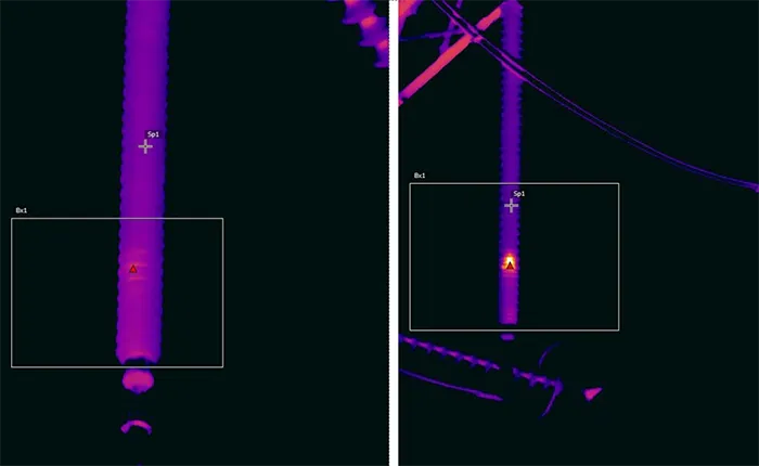
Fig. 12 offers an example of combined analysis. The left photo suggests a change in electric field grading given the low intensity of corona discharges compared with neighbouring phases. Looking at IR images of that same insulator (see Fig. 9 left) offers another indication that there may be an internal problem. Finally, inspecting that insulator from the opposite side and from a greater distance allows the internal defect to appear more distinctly (see Fig. 9 right). It would not have been possible to conclude that there was severe internal damage only by looking at the first UV or IR images.
Such a systematic analysis needs to be performed for each indication of possible internal damage.
Status Assessment
This large-scale project included numerous substations and approximately 1000 insulators. It has therefore been important to generate continuous status assessments based on the findings from visual, IR and UV-inspection as well as from combined analysis using all techniques.
Status assessment has been performed using the traffic light principle based on four colours:
• Green: Insulator looks fine;
• Yellow: No evidence of damage or deterioration but some remedial measure may be needed (most often fixing poor electric field grading);
• Orange: Signs of light damage or deterioration. Insulator will require some countermeasures and follow up inspection;
• Red: Indication of internal damage and insulator must be replaced.
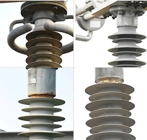
For example, referring to Fig. 13, the insulator with GREEN assessment has a hydrophobic surface, its grading ring appears to be properly positioned and there is no visible deterioration. The insulator with YELLOW assessment has no grading ring and slight deterioration of its housing is visible. The insulator with an ORANGE assessment has no grading ring and corrosion on its end fitting has started to compromise its seal integrity. The insulator with a RED assessment has no grading ring and traces of severe discharge activity some distance from the end fitting. As confirmation, several insulators deemed “RED” were removed from service for dissection which revealed the presence of internal defects.
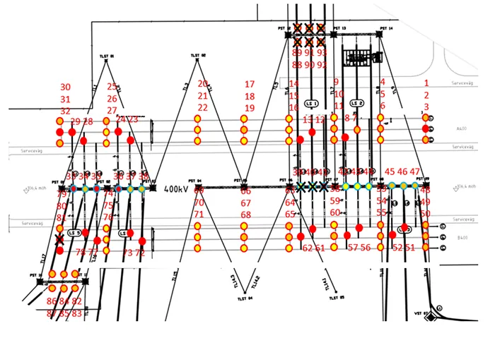
When the status assessment for any substation has been completed, this is overlayed onto its layout to help prioritize replacement of composite posts with porcelain equivalents (see Fig. 14). This is performed for each substation where composite station post insulators are still installed.
In addition, all substations are listed with overall population of posts and latest status assessment for each (see Table 1). It should be noted that insulators deemed RED might have a damage level anywhere from 3% to 35%, which allows prioritization when it comes to the urgency to remove these from service.
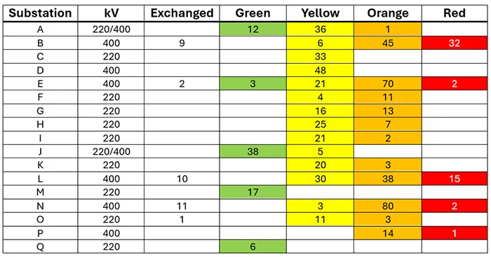
It is interesting to note that Table 1 reveals a pattern with more insulators becoming ORANGE and RED at 400 kV substations rather than YELLOW and ORANGE at 220 kV substations – even after a similar time in service. This is due to excessive electric field strength causing premature ageing of composite insulators. Implementation of electric field strength limits already set in IEC 61109 is clearly important, but this must also be implemented in all other composite insulator standards.

Countermeasures
While it has been planned that all composite station posts will eventually be exchanged for porcelain, there are cases where this is not feasible, e.g. when foundations or metal stands have not been designed to withstand the increased load. As a result, some composite post insulators will be subject to countermeasures other than replacement with porcelain. Fig. 15 shows one such case.
Here, the insulators are equipped with grading rings installed, but these have been poorly designed leading to excessive electric field strength along and within the insulators. However, since there have not been indications of severe deterioration these insulators are still considered fit for purpose. Instead of replacement, grading rings on these insulators are being repositioned to reduce electric field strength and the insulator can be kept in service for the balance of its expected life.
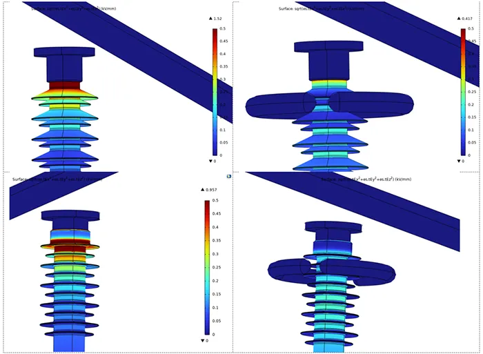
Fig. 16 offers an example of re-designing the grading ring on a 400 kV insulator. The ring was moved down by 80 mm which reduced maximum electric field strength along and within the insulator by about 35%.
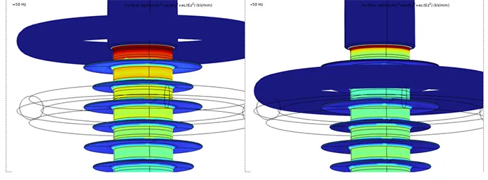
Another such example is where a 220 kV substation is planned to be rebuilt in 5-10 years and where composite stations posts will be left in service until this refurbishment. The countermeasure in this case was made more complex by the fact that there were two different manufacturers and designs of these insulators. On some insulators, minor deterioration had already started to appear that included peeling of the sealing and corrosion on the end fitting. While it would normally take time for such degradation to evolve into severe damage, to lower risk it was decided to introduce grading rings, employing a single design to provide protection for both insulators. Simulations with and without grading ring were performed and it was found that a 70% reduction in maximum electric field strength along both insulator designs could be achieved with rings installed (see Fig. 18).
Finally, for a few substations it was decided to leave these without any modification to or replacement of their existing composite station posts. Based on inspection, these were deemed in satisfactory condition after slightly more than 10 years in service. However, given lack of any documentation from testing or factory acceptance procedures, it was still deemed a risk that the quality of the post insulators would be adequate. As such, these substations will be subject to inspection every few years over the course of their residual technical lifetime.
Conclusions
Valuable lessons have been learned during this project. Looking at insulators, the most important of these is having up-to-date specifications when purchasing and installing composite insulators. The additional expense and effort during procurement will easily be exceeded by the cost of frequent inspection of insulators if quality is lower than expected.
From the inspection point of view, a key finding for all camera operators has been that findings are generally only indications that need to be verified from other angles and using other sensors to be fully understood. For station post insulators, for example, most cases of internal damage develop only on one side, meaning that inspection from a single direction will not be sufficient.
This research identified and continuously measured cases where internal damage developed and subsequently propagated along insulators. This provided insight into propagation rate for these types of damage as well as how high electric field can break down not only dielectric materials but also the galvanized layer of end fittings.
There have also been important examples of how best to identify and assess different types of IR and UV images. Hopefully, these will serve to spread knowledge on proper diagnostics for composite insulators. The examples discussed above show that damage propagation is generally a slow process, meaning that a utility will likely have sufficient time after identifying damaged composite insulators to safely replace them.
Finally, utilities should not place overreliance on manufacturers and suppliers. Moreover, while important documents have been published over the past 15 years with regards to maximum permissible electric field on composite insulators, examples still exist of such insulators being installed with no or inadequate field grading. An up-to-date technical specification is required to ensure product quality. In addition, these inspections have demonstrated the importance of following-up installations and quality control of incoming materials.
References
[1] M. Radosavljevic, I. Gutman, C. Ahlholm, P. Sidenvall: “Ageing and deterioration of composite post insulators exposed to high electric field in 220 kV and 400 kV switchyards in Swedish network”, 2017 CIGRE SC B3 Colloquium, Recife, Brazil, 18-20 September 2017.
[2] P. Sidenvall, A. Sandoval, A. Taheri, J. Remelin: ”New competencies and diagnostic methods needed for the application of composite insulators in substations”, Cigre Session Paris, B3-10795, 25-30 August 2024, France.
[3] CIGRE WG B2.21: “Guide for the assessment of Composite Insulators in the Laboratory after their Removal from Service”, CIGRE TB 481, December 2011.
[4] STRI Guide: “Guide for Visual Identification of Deterioration & Damages on Suspension Composite Insulators”, STRI Guide 5, 2005.
[5] EPRI field guide: “Visual inspections of polymer insulators”, ID 3002005627, 2015.
[6] CIGRE WG B2.21: “Assessment of in-service Composite Insulators by using Diagnostics Tools”, CIGRE TB 545, August 2013.
[7] EPRI Yellow book: “Overhead Transmission Inspection and Assessment Guidelines – 2006”, ID 1012310, 4th edition, November 2006.
[8] IEC Standard: “Insulators for overhead lines – Composite suspension and tension insulators with AC voltage greater than 1 000 V and DC voltage greater than 1 500 V – Definitions, test methods and acceptance criteria”, IEC 61109 Ed. 3, 2025.
[9] A.J. Philips, A.J. Maxwell, C.S. Engelbrecht, I. Gutman: “Electric Field Limits for the Design of Grading Rings for Composite Line Insulators”, IEEE Transactions on Power Delivery, Vol. 30, No. 3, June 2015, p.p. 1110-1118.
[10] I. Gutman, P. Sidenvall: “Optimal Dimensioning of Corona/Grading Rings for Composite Insulators: Calculations & Verification by Testing”, INMR World Congress, Munich, Germany, 18-21 October 2015.
[11] P. Sidenvall, et al.: ”Limits of electric field for composite insulators: state-of-the-art and recent investigations of overhead line insulators purchased by power utilities”, CIGRE Science & Engineering, N. 24, February 2022.
[12] P. Sidenvall, F. Lehretz: “Key factors for reliable results in E-field simulations of OHTL insulators”, CIGRE Symposium, paper 10265, September 29 – October 3, Montreal, Canada, 2025.