High voltage substation surge arresters play a vital role protecting equipment from surge-induced overvoltages. This applies in seismically active as well as in non-seismic areas. However, unlike other critical components, they are not essential to immediate restoration of power following an earthquake. Given this, James Taylor of Hitachi Energy Sweden proposes a more practical approach to defining their seismic performance requirements in AIS applications. In this edited contribution to INMR, he explains that while seismic resilience is of course important, stringency of these requirements for surge arresters can be moderated versus other equipment.


Surge arresters are crucial in high-voltage (HV) substations for protecting equipment from transient overvoltage events, such as lightning strikes and switching surges. However, in the context of seismic events, their role is secondary when compared to other substation equipment that are directly required for restoration of power, such as transformers, circuit breakers, etc.
There are several international and country-specific standards used for seismic qualification of HV substation equipment. IEEE 693 is probably the most widely referenced to define seismic requirements and offers generalized guidance on seismic qualification for all types of substation equipment, including surge arresters. However, surge arresters are generically grouped with other equipment that have higher operational criticality.
While acknowledging that adequate confidence is needed that the structural integrity of surge arresters be maintained during earthquake, their function is not essential for immediate restoration of power following seismic events. There is therefore the opportunity for a more moderate, while still effective, approach to defining their seismic performance requirements.
While surge arresters should be expected to withstand seismic loads, the following sections discuss considerations and criteria under which HV AIS surge arresters may not have to uphold the same stringent seismic performance requirements as other key substation components. IEEE 693 requirements are specifically referenced, but the same principles and objectives could equally be applied to demands for qualification methodology for any seismic specification.
Key objectives are to:
1. Demonstrate that the operational priority of surge arresters in post-earthquake scenarios can be set lower than that of other substation components;
2. Propose a more tailored seismic performance requirement for surge arresters that balances cost, practicality, and structural resilience;
3. Provide recommendations for practical seismic qualification methods, including appropriate testing for surge arresters that will ensure adequate, but not unrealistically stringent, seismic performance.
Surge Arrester Function
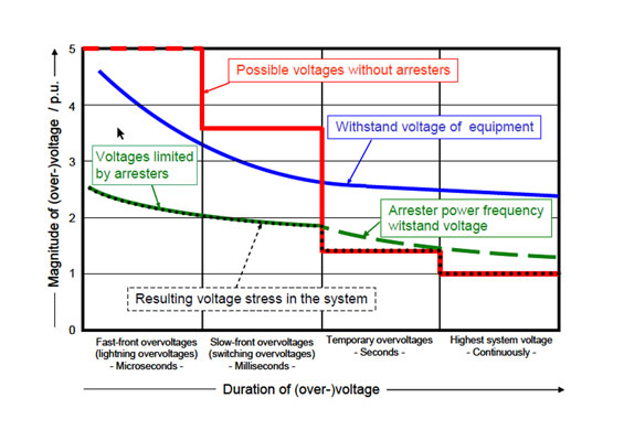
Surge arresters are selected based mainly on their electrical characteristics to protect against harmful overvoltages against which an electrical system cannot possibly be economically designed. Optimizing surge arrester design, connections to and placement in the network for use over many years is clearly advantageous for system reliability.
Slim, compact surge arresters placed as close as possible to the protected object (e.g. on a transformer tank), and connected by light, slack, near-vertical droppers are typically optimal and the arrangement of choice for surge protection. However, these may be deemed too weak and flexible for use in seismic zones. This is especially so if their support structure is mounted on a transformer tank, bracket or pedestal that could significantly amplify the ground acceleration load transferred to the arrester.
A different arrester style with greater mechanical withstand may thus be chosen, even if it is less cost-effective and technically optimized. It may even be necessary to site the surge arrester away from the equipment it protects, such as on a standalone purpose-designed pedestal to reduce the seismic amplification factor. But this could result in diminished overvoltage protection (due to separation effects), added cost, and a larger overall station footprint.
Surge arresters have a nominal design life of 30 years, handling surges many times, yet a less-effective design may end up being selected based only on a low-likelihood event that may not occur. Hazard versus risk (in combination with appropriate consideration of consequences) should therefore form part of their seismic evaluation criteria.

Hazard Versus Risk
A commonly used approach to define seismic hazard is to describe the probability of ground motions that are significant enough to cause major harm or damage. This is characterized by, for example, peak ground acceleration (PGA), i.e. maximum acceleration of the ground during an earthquake. Seismic risk is then the probability of occurrence (over some time period) of adverse consequences due to the seismic hazard. Overall risk is a combination of the seismic hazard occurrence and a given structure’s fragility to being damaged by the hazard..
Consequences of damage are often expressed in terms of:
1) Deaths and casualties;
2) Damage (cost due to failure); and
3) Downtime (power interruption in the case of HV substations).
When evaluating seismic hazard, an input ground motion should be selected based upon level of acceptable risk. A common approach used in seismic design is to choose the ground shaking that, on average, will be reached or exceeded over 475 years. This average return period has an annual exceedance probability of 1/475 = 0.21%, and the chance the ground acceleration will be met or exceeded in an exposure period of the nominal design life of a surge arrester, i.e. 30 years, is: (1-1/475)30 = ~94% chance it will not occur, ~6% chance it will occur.
A user may alternatively decide to take a conservative approach towards assigning risk, and design for earthquake accelerations that have a much longer mean recurrence interval over a longer exposure period, for example using a 2475-year return period.
Probabilistic ground motion with a given return period is not known with certainty. Return period is simply a way to express an annual and long-term average probability. Hence, there is no absolute validity in return period defining the timing of an occurrence, nor that the occurrence is certain to happen during the life of the surge arrester. Pragmatically, multiple seismic hazard levels could be assigned with differing return periods, and each with corresponding alternative withstand performance expectations based on associated risk of occurrence.
Assigned seismic hazard and risk is usually generically applied to all equipment in any substation. Thereafter, seismic standards judge all equipment equally vulnerable and have equal consequences for factors
1), 2), 3) above. What is typically not taken account of is that these consequences are individual to each specific piece of apparatus, and how their possible mitigation can differ.

Applicable Seismic Standards
To properly evaluate valid seismic hazard and risk, it is best to use a site-specific response spectrum that accounts for soil type and other geological conditions at the location. However, for simplicity, generic design rules and guidelines are often specified by users, including reference to building codes.
Building codes cover design of buildings and other structures to be used in seismic regions where risk to life and structural damage must be reduced. Generalized rules apply for earthquake-resistant design of buildings and elements constructed with various structural materials. Clearly a building code and structural design criteria has no relevance to a surge arrester. As stated in IEEE 693, “The mechanical properties and characteristics of insulators, which have good insulating/dielectric properties, are different from materials typically used as load-resisting structures. Codes and standards for seismic design (e.g. ACI 318, AISC 341, ASCE 7, ADM) were developed to address commonly used structural materials (e.g. concrete, steel, aluminum) and do not address the design of insulator materials.”
Application of building code methodologies to substation equipment and structures, including those that have sections specifically for non-building structures, can be problematic and these cannot be used to appropriately evaluate a surge arrester. Building codes can be useful for providing insight into the expected level of seismicity of a location, and thereafter selecting an appropriate apparatus qualification level according to more appropriate seismic guidelines.
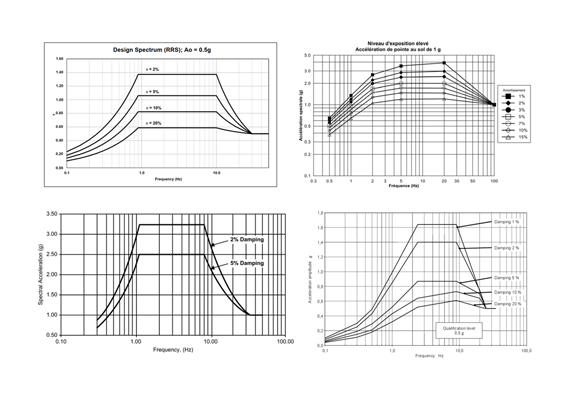
Neither earthquake intensity nor earthquake magnitude present any information about the frequency content of the earthquake. For engineering/design purposes, other representations are used, e.g. recorded ground accelerations or response spectrums (see Fig. 1).
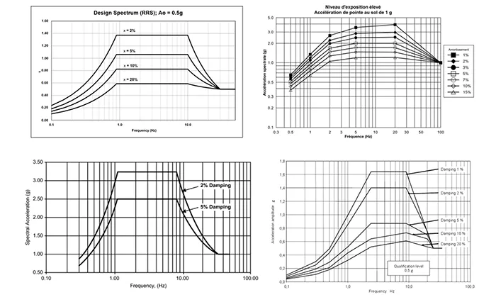
Three seismic qualification levels are specified: high, moderate, and low, which are defined by the zero-period acceleration, ZPA, (peak ground acceleration) and corresponding response spectra for respective percentage modal damping. Performance Level qualification is a response spectrum that directly reflects the accelerations associated with meeting the seismic qualification objective at the specified qualification level. Design Level qualification uses a spectrum defined by halving the Performance Level accelerations, while requiring a safety factor of at least 2 to the arrester’s assigned seismic strength, i.e. < 50% mechanical strength is utilized.
“Seismic qualification objective” in this context is to secure that the surge arrester will not sustain damage of such a nature or extent that they a) cease to perform their electrical function, or b) are at risk of imminent collapse at nominal electric operating conditions.
While complete and total fracture can be considered significant damage, it is important to understand that yielding is permitted provided it does not impair electrical function or pose risk of imminent collapse. Since damage not deemed significant can be tolerated, it can be acceptable for equipment such as surge arresters to be repaired or replaced after an earthquake.
Surge Arrester Considerationss
Surge arresters are not system critical for reinstatement of power after an earthquake. Alternative considerations should therefore apply compared to other, more critical, equipment. Otherwise, with due consideration to expected arrester cost and function, requirement for disproportionate strength safety margins could result in a sub-optimal design and additional project cost. As such, seismic impact of surge arrester performance should be assessed in the context of the following considerations.
Design
Seismic specifications typically focus on defining seismic strength of apparatus insulators based on some form of generic mechanical testing criteria applicable to apparatus. These are typically not synchronized with the mechanical testing according to surge arrester standards IEC 60099-4 or IEEE C62.11 used for the respective designs.
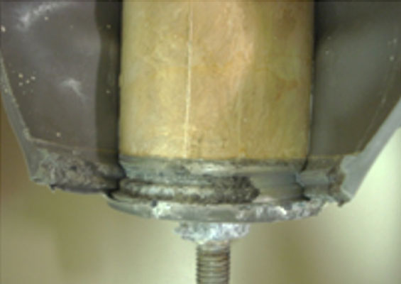
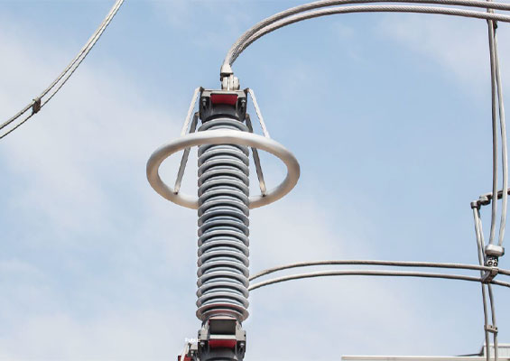
There are 3 fundamental gapless metal-oxide surge arrester designs used in traditional HV AIS applications: a) porcelain-housed hollow-core, b) polymer-housed hollow-core, c) polymer-housed solid-core (see Fig. 2).
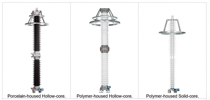
Following is a review of the considerations regarding defining seismic strength for each design.
1. Porcelain-Housed
IEEE 693 Annex X expects 10 samples of porcelain-insulators to be tested to breakage to accept a 100% (safety factor 1.0) loading of the 2 standard deviation value to the arithmetic mean (MBL – 2) for Performance Level qualification. With a test of 3 samples, the limit is set to 80% (safety factor 1.25).
For porcelain-housed surge arrester designs tested mechanically according to the IEC surge arrester standard, 3 samples are to be tested for MBL and SSL. MBL is to be at least 120% of SSL and SLL is defined to be safely set at 40% of SSL. These respected loads are defined below:
• SLL: Specified Long-term Load
i.e. force perpendicular to the longitudinal axis of an arrester, allowed to be continuously applied during service without causing any mechanical damage to the arrester.
• SSL: Specified Short-term Load
i.e. greatest force perpendicular to the longitudinal axis of an arrester, allowed to be applied during service for short periods and for relatively rare events (for example, short-circuit current loads and extreme wind gusts) without causing any mechanical damage to the arrester.
• MBL: Mean Breaking Load
i.e. average breaking load for porcelain or cast resin-housed arresters determined from tests.
For example, assume a surge arrester porcelain insulator has been mechanically tested on 3 samples, and has a verified SSL = 7.5 kNm, SLL = 3 kNm, MBL = 12 kNm and MBL-2 = 9 kNm. Since only 3 samples were tested, 80% of 9 kNm = 7.2 kNm is the assigned limit for seismic strength. However, this value is considered unnecessarily low since it is below the guaranteed SSL withstand value, and a higher value than SSL can be permitted for extremely rare seismic loads. The value proposed is especially conservative in the case where all the results are greater than MBL-2σ.
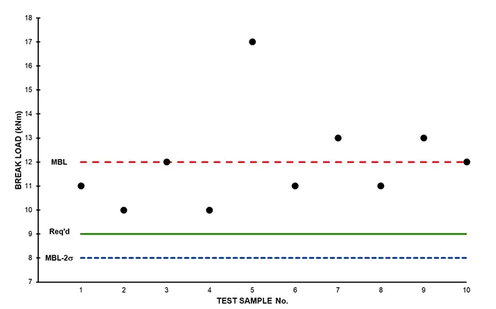
This methodology presumes that all samples have consistent break values or that there is a scattering of results above and below a close statistical average. It is reasonable to expect that there will be a spread of break values when a large population of porcelain insulators are tested, but there is no account taken for the case where the minimum value is always well above the required load. For example, assuming a certain arrester insulator style has been mechanically tested on 10 samples, and 9 out of 10 have a break load in the range 10 to 13 kNm, but one sample broke at the much higher value of 17 kNm. Moreover, assume the verified MBL from the samples is determined to be 12 kNm, noting that no sample broke under 10 kNm. Presuming that the seismic load required to be withstood in a specific case is 9 kNm, then the results show that all samples are above this with good margin. However, because 1 out of the 10 samples broke at a much higher value, this disproportionately skews the standard deviation, such that MBL-2σ = 8 kNm, i.e. below the required 9 kNm despite all samples actually being well above. This scenario is depicted in Fig. 3. Increasing sample size may not necessarily improve the situation since only one additional sample with a much higher break load could result in the MBL-2σ value being even lower. Yet still without any of the results having fallen below the minimum needed.
For porcelain hollow-core insulators produced to IEC 62155, a routine bending test is to be performed on every insulator supplied. The standard requirement is for a value of 50% of withstand bending moment. However, an option to increase this to 70% of the specified mechanical failing load is also given. Such tests should be conducted in 4 mutually perpendicular directions. This could be considered sufficient validation of the required mechanical strength in many cases in lieu of a once-off round of break tests, i.e. when the routine mechanical tested value is at least equal to the seismic loading, and the safety factor to a proven withstand test value then only needs to be >1.0. In case of need, order-bound insulators could possibly be tested at a somewhat higher load value to validate the seismic load withstand, while not being so high that they are at risk of being damaged. For example, in the above case with MBL = 12 kNm, testing at 9 kNm would equate to a load ratio of 9/12 = 75%; which may be acceptable after agreement between the porcelain manufacture and the arrester manufacturer.

2. Polymer-Housed
Polymer-housed surge arrester designs mechanically tested according to the IEC standard have similar definitions for SLL and SSL, except that there is no fixed relationship between them (manufacturer defined). Moreover, SLL is to be applied in a cyclical manner over 1000 cycles to capture any potential fatigue effects due to the flexible nature of polymer-housings that could affect SSL and ultimately break load. MBL does not strictly have to be investigated, though it could easily be included in the testing sequence if deemed advantageous by the manufacturer.
A. Hollow-Core Polymer-Housed (Composite Insulator)
IEEE 693’s Annex X composite insulator acceptance criteria for Performance Level qualifications is that load upon the insulator does not exceed 100% of SML. Further, SML is referenced to MML by the factor 2.5 x MML. These loads are defined (according to IEC 61462) as follows:
• SML: Specified Mechanical Load
Ie. load specified by the manufacturer that is used in the mechanical tests.
• MML: Maximum Mechanical Load
i.e. highest mechanical load which is expected to be applied to the hollow insulator in service and in the equipment in which it is used.
SML, in brief, is a load that the insulator can maintain for a period of 1 min. It is a “rated” load, which is confirmed by test to be achievable, but it is a subjective rather than an objective quantity. Further, although it may place the insulator in an irreversible plastic phase, it is still below the actual failure bending load. By the nature of their production, composite insulators do not tend to have the same potentially wide statistical spread of mechanical strength as for brittle porcelain insulators. Hence only one sample is required to be tested [5] in three, or possibly four, steps of increasing applied load: a) MML, b) 1.5x MML, c) 2.5x MML = SML, d) to failure (optional). Nonetheless, an arrester manufacturer may specify that several samples be tested to provide a more statistically robust result and can also set other criteria as deemed appropriate.
IEC 61462 is a generic standard for composite hollow-core insulators and not specific to surge arresters. Furthermore, surge arrester standards [2, 3] make no reference to MML or SML as part of their mechanical testing requirements. It is, however, reasonable to presume that the requirements placed on the supplier for production of the composite insulators could be made according to IEC 61462. It is therefore justifiable to set the defining seismic strength equal to SML and validate it by appropriate mechanical type testing.
A routine mechanical test is also to be performed on every produced composite insulator. Similarly, to as discussed above, this test could be considered sufficient to verify the seismic strength of the order-bound insulators against that to be applied during an earthquake, and so avoid the need for repeatedly performing a test of SML (in cases when a user may require a revalidation).
B. Solid Polymer-Housed
Polymer solid-core surge arresters are addressed in a slightly different manner from the requirements of hollow-core housings since SML is not explicitly defined for such designs. Instead, the manufacturer can define a corresponding value for SML based on appropriate mechanical testing.
Ultimate cantilever load experienced during shake-table testing should not exceed 100% of the manufacturer-defined SML for solid-core polymer arresters. Notwithstanding, it should also be considered that, even in a rare case of a surge arrester failing during seismic activity, the direct impact on the electrical grid’s ability to recover and restore power immediately is likely minimal with this type.
A fact often overlooked in the case of solid polymer designs is that, while a physical mechanical breakdown beyond the deformation limit may affect its ultimate load carrying capacity, in contrast to hollow-core designs it need not necessarily affect its inherent electrical function. Obviously, individual designs need to be evaluated on their merits, taking account of manufacturer-assigned values. The effect of breakage on electrical performance has been investigated on a solid-design type surge arrester by the following test steps and results:
• Electrical characteristics measured: Reference voltage, Partial discharge, Power losses.
• The arrester was mechanically loaded until the point of physical breakage – determined by a dip in the force vs deflection curve, and visibly observed by crack in a fiberglass loop, split in polymer housing, small gap between surge arrester module and metal base. The break occurred at a value well above the assigned seismic strength for the arrester (150%). Despite having exceeded the damage limit, the assembly remained generally intact afterwards, with only a minor remnant deflection from the vertical.
• After breakage, electrical characteristic measurements were repeated: No perceivable change in reference voltage, partial discharge or power losses were noted
The test showed that this type of surge arrester can still function (at least in the short term) even after mechanical damage – physically intact and with electrical contact maintained, indicating that the arrester would still be capable of remaining connected to the network and provide surge overvoltage protection even when broken. Moreover, the mold-bonding production process used in this design ensures sealing along the entire length, meaning that a split in the housing would not immediately lead to moisture ingress propagating further to cause a short-circuit of the internal elements.
Inspection of the entire plant is always warranted after an earthquake regardless. While replacing an individual arrester may eventually be needed, the arrester could remain in service in the damaged state until after the crisis has passed.

Mechanical Limits
As per IEC 60099-5 cl 5.2.2.7.12, SSL as a withstand value verified in bending moment tests is intended to cater to rare events such as short-circuit loads or high wind gusts. Earthquakes, however are considered extreme and extremely rare. In this same clause it states “It is important to note that SSL does not cover any seismic loads, which may require much higher SSL values than usually applied for normal service conditions, and which therefore needs special consideration…”
Hence it is understood that the load limit for which seismic loads are to be evaluated is greater than the standard defined SSL. How much greater may be design-dependent, as discussed earlier, but the security of the results can be assured by making appropriate specification of mechanical testing relevant to surge arresters. For example, testing SLL on a polymer-housed arrester over 1000 cycles already accounts for potential fatigue effects during normal operation, which may be considered sufficient. A shorter duration vibrational test at higher load (and frequency) could easily be adopted if it is deemed necessary to assign a “specified seismic load”. Conversely, in those cases where the seismic loading requirement is evaluated to be lower than the standard SLL or SSL, respectively, the user can have high confidence that the arrester is not at risk of being mechanically damaged and hence a safety factor of >1.0 would be deemed sufficient.
A degree of responsibility for the overall seismic security of the substation should also be taken by the system operator and not simply place all demands solely on the surge arrester manufacturer. In the event of high mechanical demands, or remnant concern that a damaged arrester could lead to consequential damage of other primary plant, then additional recommendations can always be incorporated by the user themselves in their own procedures and policies, e.g. install polymer housings in preference to heavy brittle porcelain, arresters to be shunt-connected and not used as mechanical support, pedestal redesign, etc.
Type of Housing
Prior to the advent of polymer-housings on surge arresters in the mid 1980s, the only choice was to use porcelain-housings and their shortcomings in seismic performance (notably heavy mass, brittle fracture mode and statistical spread in break load) had to be accepted. Polymer housings inherently resolved these issues due to their relative light weight, flexibility, and different production methods. It has primarily been the conservative nature of the electrical industry that has slowed the wholesale transition to polymer-housings. However, specific use of silicone for the housings (rather than generically “polymer”) worldwide has overcome past concerns since it has proven to be UV stable, even at high altitude, pollution resistant, even under extreme conditions, and able to handle installation under a variety of physical and environmental conditions. Silicone as the housing on surge arresters has been used for almost 40 years (60 years on other apparatus) and is well-proven. In many regions with known high seismic activity, the preference is to use only silicone (polymer) housings on all electrical substation apparatus. There should no longer be any technical justification for users to exclude use of silicone-housed surge arresters in preference to porcelain-housed and silicone housings should also be the design of choice in seismic area.

Connection
Surge arresters are an active protective device, which may acceptably overload as part of its normal operating duty, for example due to surge energy injection beyond its rated handling capability. To mitigate consequential effects, arresters are inherently not intended to be permanently mechanically loaded in service to any significant extent.
Irrespective of whether the phase conductor is a long horizontal dropper or a heavy bus construction, the use of an arrester to support the conductor means it is acting principally as a support insulator. Surge arresters are not intended to be used as mechanical supports and are not designed nor tested for this kind of heavy physical duty. They are typically expected to be connected by use of a light, slack, and near-vertical dropper in shunt-connection rather than having the arrester directly in series with the phase conductor. This reasoning is exemplified in the standardized short-circuit (pressure relief) type test for surge arresters, wherein connections are specified to be made using a conductor which is slack, vertical, and flexible, i.e. as per the recommended installation method.
A similar configuration is proposed for “seismically suitable” connections in IEEE 1527. It has been established that flexible conductors configured with appropriate length will provide the desired flexibility and conductor movement without applying excessive force to the connected equipment terminations. Although vertical drops have not yet been specifically studied, it is nonetheless recommended that these should be designed with sufficient slack to allow for the expected relative displacement between their interconnection points. At present, conductor interaction effects need only be considered for equipment that are primarily interconnected horizontally, and so conductor loading on arresters connected by vertical droppers – since they are intended to be – could in fact be neglected altogether.
Notwithstanding that surge arresters do have rated mechanical loadings, as discussed, actual load applied in service should always be limited by installing them using good engineering practice. When connected appropriately, normal operational (continuous) loading is negligible. Further, by making connections in the proper way, the arrester will also not be loaded significantly at the line terminal by dynamic loads from external factors, e.g. short-circuit, conductor movement, etc. Hence, large forces from conductor interaction should not need to be applied to a surge arrester even during an earthquake, and proposed concurrent line pull loads could justifiably be removed (reduced significantly); perhaps with the added requirement that the installation is made by the user with “seismically suitable” connections.
Mounting
For the sake of seismic qualification, equipment compliance depends largely on amplification factor of the support structure the arresters are mounted on. When the expectation is to use a generic structure factor, as much as 250% amplification is applied to the required response spectra (RRS). In the words of one seismic lab: High Performance Level ZPA = 1 g x 2.5 = 2.5 g isn’t an earthquake, it’s an “apocalypse”! Since HV AIS surge arresters typically have an eigen frequency in the region of 1 – 8 Hz (when seismic dampers are not used), this puts the greatest load on them from the peak of spectra.
For High Performance Level qualification this can result in evaluation/test at 3.24 g x 2.5 = 8.1 g, which is extreme and unjustified compared to what can really occur. In addition, this amplification is applied to the entire RRS, when any potential amplification would occur at a single frequency and not over the whole frequency range. Also, the assumption is that the structure and arrester go into resonance at the same frequency and by the same mode, which is unlikely.
A user in a seismic zone would be equally concerned about seismic performance of the support structure as the effect on the equipment mounted on it. It can therefore be argued that a 250% amplification of the ground acceleration is unrealistic for surge arrester support structures that are used in practice. Seismically suitable structures can be designed which do not amplify ground acceleration by a significant amount and, from experience, the amplification factor of supports of typical switchyard equipment is known and significantly lower – often in the order of magnitude 1.0 to 1.5.
Studies have shown that simple and symmetrical equipment mounted on typical steel supports is subject to support amplification that closely resembles that of a single degree of freedom (SDOF) oscillator mounted in series with a secondary spring element. Hence, typical substation steel supports act as simple spring elements, introducing flexibility and reducing eigen frequencies. For equipment with eigen frequencies below approximately 10 Hz, which essentially applies to all main substation circuit apparatus including surge arresters, a generic support amplification factor of 1.5 will suffice, for all but perhaps the worst seismic designs.
Unlike other substation equipment, mounting structure is not within the surge arrester manufacturer’s scope of supply. Even if it would be, there are many permutations and combinations across multiple users that make this impractical or uneconomical. Hence, it is left to the supplier of the support structure to ensure that an appropriate structure is used, with the necessary structure amplification factor to uphold the designated safety factor at the arrester base.
Surge arresters may on occasion be mounted on the transformer tank to uphold the shortest possible protective distance to the transformer bushings as well as to save space in the substation. The installation arrangement can use an outrigger platform/bracket, which could potentially transfer a significantly higher seismic load onto arresters compared with on a ground-mounted pedestal. Each case would need to be evaluated but it has been shown possible to design seismically stiff platforms even for such applications, which would be preferable. Otherwise, arresters can either be fitted with seismic dampers or be mounted elsewhere – which could have negative consequences, e.g. added cost, clearance issues, separation effects, station layout and size.
When the surge arresters are to be mounted on user-supplied support pedestals, this may involve different pedestals for use in separate locations. Rather than the arrester manufacturer having to review and re-review the structure amplification factor for each separate project, it should be defined by the user which is their “most seismically vulnerable” structure. This means that the user is expected to have made evaluations on the entire population of their arrester structures to calculate the support pedestal loadings, and so be able to define the actual structure factor for the most seismically vulnerable case to the arrester manufacturer, and not vice-versa.
Unfortunately, users do not always do this and instead define support structure as “unknown” and so expect the maximum prescribed structure factor be applied, despite it being understood it will be much lower.
With consideration to the above, the definition of “support parameters are known” could be taken to mean any kind of traditional steel support pedestal on the ground as commonly used in substations, e.g. pipe, box, lattice construction. Surge arresters mounted on this type of support structure could then be qualified without specific and separate evaluation of the pedestal using a structure factor in the range 1.0 to 1.5. This would apply to equipment that is to be qualified by analysis as well as by testing. Thereafter, the definition of “support parameters are unknown” would be applicable to use a higher generic structure factor only for other non-traditional support structures, e.g. not steel but concrete or on a particularly unusual style/design of support bracket.
Replacement & Spares
Since surge arresters are not crucial for immediate post-earthquake recovery, there is an opportunity to implement post-event inspection protocols. After an earthquake, surge arresters can readily and easily be inspected, fixing hardware retightened and other minor remedial work made as required or, if necessary, completely replaced quickly and with minimal downtime – surge arresters do not take a long time to install, nor do they require commissioning tests before taking into service.
By comparison with most other HV substation equipment, surge arresters are relatively inexpensive and compact. Consequently, keeping spare surge arresters on hand would not require a large capital investment nor take up significant space in storage. It is therefore reasonable to expect it to be possible to hold spare surge arresters on site – at least at key substations in seismic areas. Hence, the most stringent of criteria for seismic qualification need not apply where replacement equipment is available and planning an outage for their installation is manageable.
Seismic Qualification Method
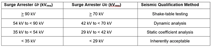
The method to be used for seismic qualification of surge arresters is commonly defined by either system voltage (Us), arrester rated voltage (Ur) or arrester continuous operating voltage (Uc or MCOV). See Table 1 for example.
There is a significant difference in the work and cost involved between evaluating a surge arrester that is inherently acceptable (no detailed evaluation needed), through performing analyses (requiring expertise and specialized programs), to undertaking full-scale testing (time-consuming and costly at a qualified laboratory with shake-table facilities).
Also, there are inconsistencies in the reasoning behind the methods and methodology for how to seismically qualify a surge arrester when based solely on voltage rating, including:
1. The voltage rating of a modern-day surge arrester is determined by the quantity of MO resistors inside. The mass of an arrester is determined by housing style, size, and number of units, together with type and quantity of MO resistors and metallic spacers, and so too are seismic parameters such as center of gravity, stiffness, modal frequencies, etc.
Regardless of whether the defining criteria is Ur or Uc (MCOV), a surge arrester housing will not change significantly in the ultimate seismic performance because of a minor difference in kV rating. For example, an arrester with Ur 84 kV / Uc 67 kV is likely to be used on a Us 100 kV system and so is one with Ur 90 kV / Uc 72 kV. The former would be able to be qualified by analysis whereas the latter would require to be shake-table tested. This is despite that they are highly likely in the same physical housing and the difference in mass could be as little as ~0.5 kg – in fact, it could be lower for the higher Ur, depending on the mass of metallic spacers used compared with the MO resistors.
2. 2. An arrester with Ur 90 kV / Uc 72 kV could also be used on a Us 123 kV system. Subject to design and creepage distance, this is assembled in a single-unit housing of relatively low mass and height. Modern-day arrester designs tested to current standards have high security in their mechanical load withstand, especially for single-unit designs. Even multi-unit designs – at least up to a limit of significant modal mass – can be considered to be at negligible risk of mechanical failure due to a seismic load when within the limits verified by test, e.g. not exceeding SSL or SML.
Single-unit arrester housings have become longer and can accommodate much higher ratings than in the past. In porcelain-housing, upwards of Ur 240 kV / Uc 190 kV are possible if the creepage distance demand is not high. In polymer-housings, the ratings can be even higher, and single units with upwards of Ur 264 kV / Uc 212 kV (and perhaps higher) are available. Even a multi-unit arrester today is much shorter and lighter than in the past and seismic performance is easily able to be modeled correctly.
3. For specific applications there can be a divergence between “voltage rating” and “seismic size” (mass, height, etc.). For example, a neutral-point arrester protecting a transformer neutral winding may have Uc = 0 kV assigned, as it is not subjected to any continuous voltage between neutral-ground. At the same time, other demands may require this to be a relatively tall design. According to Table 1, the arrester could be defined as “inherently acceptable” since Uc < 29 kV, or else a qualification method used, e.g. based on Ur, that is different to a phase-arrester having a comparable mass, height, etc. with other requirements for its design.
This can be particularly troublesome for defining surge arresters in specific applications within
capacitor/filter banks, HVDC, FACTS, and series-compensation schemes. These do not always uphold a traditionally defined Us, Ur, or Uc, may have “non-significant” ratings assigned due to their connection into the system, or be a multi-column design of “low rating” but with significant mass.
If Table 1 were followed, reduced seismic qualification requirements could apply, despite these arresters (with non-existent/low ratings) having a greater seismic risk due to their large dimensions being more comparable with much higher rated arresters. It is equally undesirable to deem them to be “non-categorized equipment” since this would restrict qualification methods to time history shake-table test or dynamic analysis only. This could result in requiring more arduous and costly work than a corresponding standard application type.
Alternative Seismic Qualification Method
With consideration to the above issues, alternative considerations are proposed to define an appropriate qualification method based more on a relationship to seismic size/vulnerability.
From experience, the first modal frequency for tall and slender symmetrically built equipment such as a surge arrester is always dominant and contributes to the largest portion of seismic loading. Any subsequent higher modes are of lesser interest and have minimal influence. For simplicity, surge arresters can be suitably evaluated for seismic performance by a static coefficient calculation that removes need to consider actual modal frequencies by assuming the arrester is subjected to the peak of the RRS. Static coefficient for surge arresters can be taken as 1.0 in seismic analysis.
Due to the nature of the arrester product, it has not been seen that all 3 earthquake directional components will cause maximum response at the same instant. A simple static analysis is sufficient by considering seismic loading applied solely from the first modal frequency in the separate orthogonal directions acting individually and alone without interaction. The resulting horizontal force is distributed proportional to the arrester’s total mass distribution and hence applied at the designated centre-of-gravity. Only cantilever loading in the horizontal direction need be considered since arresters are relatively stiff and strong in the vertical direction. Vertical ground acceleration is of little consequence to their seismic performance.
Static analysis – especially with good input data for stiffness and damping – has been shown to mirror shake-table test results very well for a surge arrester; both in terms of eigen frequency and mechanical loading. The Force vs Deflection characteristic is available from measurements made as part of standardized mechanical bending type tests, and the result can readily be used to derive the stiffness of the arrester. A generic value of 2% modal damping is suitable to use for a conservative result.
Results from seismic test reports and case studies have shown that the simple static analysis method is sufficient to adequately estimate bending moments on standard surge arresters mounted on typical steel supports. This is especially the case when analysis assumes a peak of response spectra acceleration is applied with 2% damping, and thus Newton’s second law of motion (F = ma) can be applied to give a conservative result for a surge arrester without additional improved damping. If an improved damping coefficient is desired/required to uphold safety factors, either naturally or with seismic dampers fitted, this can be determined by performing a snap-back test on the complete assembly, and then the same simple static analysis method used with the RRS adjusted for the actual damping.
The following alternative procedure is proposed for arresters that are base-mounted on a pedestal/bracket in vertical installations. Designs with parallel columns may present extra challenges and require specific testing to define the relevant criteria, although the same methodology can generally be applied. In case of angle-mounting installation, having also evaluated the risk for dislodgment of the internal elements when non-vertical, it may be possible to assign a corresponding bending moment strength reduced proportionally by the arrester’s self-weight due to the gravitational force permanently applied at the centre-of-gravity.
Step 1
Define the seismic strength of the arrester (Md) in Nm, as determined by suitable bending moment testing, routine test, manufacturer-specific conservative value).
Step 2
Calculate the seismic bending moment (Ms) in Nm required to be withstood, by the equation:
Ms= m × as × g × k1× k2× h
where,
m = mass of arrester in kg
as = seismic acceleration at arrester centre-of-gravity, from peak of required response spectra assuming 2% damping (unless verified higher) in per-unit g.
g = gravitational constant, taken to be 10 m/s2 for simplicity.
k1 = Static coefficient factor, taken to be 1.0 for a surge arrester.
k2 = Structure amplification factor, which is either known from separate analysis or assigned a realistic value (as discussed). If necessary, the arrester manufacturer shall have the right to define the required factor that the support structure manufacturer must uphold, e.g. within the range 1.0 – 1.5.
h = height to centre of gravity in m.
Note that additional terminal load or conductor interaction effects have not been included since, as discussed, they need not be considered for a surge arrester installed with “seismically suitable” connections. If nonetheless they are to be included, the relevant value of bending moment can then simply be combined algebraically to give a total value for Ms.
Step 3
Calculate the ratio Md /Ms.
If the ratio is > 1.0 for Performance Level qualification or > 2.0 for Design Level qualification, the surge arrester can be considered seismically qualified. If not, then either a dynamic analysis or shake-table test can be used as the alternative qualification method at the arrester manufacturer’s discretion; provided this gives the required positive result. Otherwise, the design is deemed inadequate for the seismic load.
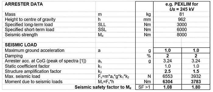
As example: A polymer-housed arrester solid-design type PEXLIM with Uc = 167 kV for Us = 245 kV has been successfully shake-table tested to High Performance Level qualification (1.0 g), including a generic structure amplification factor k2 = 2.5x. Excluding added terminal mass and conductor interaction effects for the sake of discussion, the maximum seismic load at the base in any direction during the Time History test was determined to be 5.52 kNm. If a more seismically suitable structure had been considered instead, e.g. k2 = 1.5x, and presuming a proportional reduction, the seismic load would have been only 3.31 kNm. The arrester design has rated mechanical strength of Md = 8 kNm, SSL = 6 kNm, SLL = 3 kNm, and additionally verified (3 samples) MBL = 10.2 kNm, MBL-2σ = 9.7 kNm.
Using the above procedure, the results of the analysis method showed that the same arrester gives the expected conservative result, i.e. higher load calculated by analysis than found in test, but nevertheless representative of actual performance. See Table 2, maximum load 6.304 kNm by analysis vs 5.52 kNm in test with k2 = 2.5x, and 3.783 kNm by analysis vs. assumed 3.31 kNm in test with k2 = 1.5x.
This shows that the proposed alternative method would have been sufficient for qualification purposes without the need to perform a shake-table test. It is also noteworthy that the result by analysis when using a more seismically suitable structure gave a loading of only 63% of the SSL type test withstand value.
This simplified procedure for evaluating seismic performance based on seismic size/vulnerability is considered to have the following advantages, along with potential disadvantages:
Advantages:
a) Does not require complicated math or specialized programs to make the evaluation. Based solely on mechanical and physical parameters that are already known, or easily obtained, and typically given on dimension drawings.
b) Extended length, creepage distance, parallel columns, heavy mass, and other physical attributes will inherently be captured, irrespective of the “electrical size”.
c) Arresters that have a low or no voltage rating will be evaluated equally to other arresters having the same physical dimensions.
Disadvantages:
a) Some designs, e.g. tall and/or heavy multi-column designs, may fall into the “test” category when they have not in the past.
b) Designs that used to be “inherently acceptable” will need an analysis to be made (albeit simple).
c) Additional mechanical tests may be needed to properly define seismic strength and damping, especially for parallel connected multi-column units.
It is proposed that this simple static method analysis would suffice for all pedestal- and bracket-mounted AIS surge arresters, irrespective of rating and physical size. Conversely, as done today, requiring dynamic analysis or full-scale shake table testing on “too low” rated arresters is not value-adding nor practically needed.
A possible exception could be if uncertainty exists about valid seismic amplification performance for applications on the upper range of EHV and UHV systems, e.g. Us 420 kV and greater. The system may be deemed more critical, the support structure of more intricate design, and the arrester may be more complex due to use of larger grading and corona rings. In such cases, verification by shake-table testing – preferably on the actual support structure to be used (or alternatively by Grouping based on valid previous testing) – may be beneficial to add further confidence about meeting the seismic qualification objective.
Conclusions
Surge arresters, while important for overvoltage protection, are not critical components integral to power system stability and restoration after an earthquake as are transformers, circuit breakers, etc. Surge arresters can justifiably have their seismic performance evaluated differently.
Instead of applying unnecessarily stringent generic seismic performance criteria, a more balanced approach would allow manufacturers as well as users to select and evaluate HV AIS surge arresters to meet reasonable seismic resilience without incurring technical and commercial disadvantages; to avoid e.g. rejecting otherwise optimal standard designs, over-dimensioning non-standard types, unnecessarily performing expensive full-scale tests or time-consuming analyses, etc.
This approach includes giving consideration to factors applicable to surge arresters, specifically with respect to:
• Seismic impact assessment, to understand risk and resultant cost vs. performance trade-off;
• Differentiated criteria and performance, as verified by relevant mechanical testing;
• Mechanical resilience of specific designs, including overload mode and consequences;
• Holistic approach, with manufacturer and user in partnership to devise a robust complete solution;
• Realistic post-earthquake expectations, especially when spares are available;
• Appropriate and relevant qualification method(s), with shake-table testing only when justified.
Applying a practical, cost-effective approach to defining seismic qualification requirements tailored specifically for HV AIS surge arresters will ensure they are sufficiently resilient against damage from an earthquake, while balancing performance, cost, and functional importance of substation surge arresters for their purpose to protect against surge overvoltages.

References
[1] IEEE 693, “IEEE Recommended Practice for Seismic Design of Substations”, 2018, including
Amendment 1, 2024
[2] IEC 60099-4, “Surge arresters – Part 4: Metal-oxide surge arresters without gaps for a.c. systems”,
Edition 3.0, 2014-06
[3] IEEE C62.11, “IEEE Standard for Metal-Oxide Surge Arresters for AC Power Circuits (>1 kV)”, 2020
[4] IEC 62155, “Hollow pressurized and unpressurized ceramic and glass insulators for use in electrical
equipment with rated voltages greater than 1 000 V”, Edition 1.0, 2003-05
[5] IEC 61462, “Composite hollow insulators – Pressurized and unpressurized insulators for use in electrical
equipment with rated voltage greater than 1 000 V – Definitions, test methods, acceptance criteria and
design recommendations”, Edition 2.0, 2023-09
[6] IEC 60099-5, “Surge arresters – Part 5: Selection and application recommendations”, Edition 3.0,
2018-01
[7] M. Martin, J. Taylor, M. Popic, ” Optimisation of Air-Insulated Substations by consideration of surge
arrester protective characteristic”, 11th HRO CIGRÉ Session, Cavtat, November 10 – 13, 2013.
[8] IEEE 1527, “IEEE Recommended Practice for the Design of Buswork Located in Seismically Active
Areas”, 2018
[9] D. Backström, “Support amplification factor study”, Hitachi Energy, 1JNL2368271, 2025