Room temperature vulcanized silicone (RTV) coatings for cap & pin insulators have evolved into an effective option to address pollution problems on overhead transmission lines. Coatings provide a protective layer that enhances insulator resistance to environmental contaminants, thereby ensuring optimal performance as well as service life. In regions with elevated industrial, coastal or conductive pollution, RTV-coated insulators can significantly reduce incidence of flashovers and outages. Apart from improved reliability, utilities have also reported reduced maintenance costs.
Application of such coatings in a factory setting involves a meticulous process designed to ensure a uniform and durable layer. This coating acts as a barrier against pollutants such as dust, dirt and chemical residues, preventing them from adhering to insulator surfaces. Insulators remain clean and functional, with little need for cleaning.
This edited contribution to INMR by Glenn Stapleton, Principal Engineer Lines & Cables at Powerlink Queensland in Australia, presents an extensive review of all the considerations involved in the decision to apply RTV coated transmission insulator strings in a problematic service area. It also offers a tropical usage context to the cases of successful application of this technology already in the literature.

Powerlink Queensland is the government corporation that owns, develops, operates and maintains transmission assets across Queensland with operating voltages from 110 kV to 330 kV. This network runs 1700 km from Cairns in the north to the border with New South Wales, comprising close to 16,000 circuit kilometres of lines at these voltages.
Powerlink has historically relied on glass and porcelain disc insulators to form the building blocks for transmission line insulation up to 330 kV. The primary failure mode experienced for disc type insulation in the past has been pin corrosion, particularly on lines running close to the coast in North Queensland. Service life in extreme cases of marine pollution dominated by onshore winds has been less than 15 years. Fitting new discs with zinc sleeves on the pins served only to extend service life by about 20%, i.e. only a 3 -to-5-year life extension.
Given this experience, starting 1997 composite/non-ceramic insulators (NCIs) were adopted as standard insulation for all new lines and some 22,000 NCIs were installed over the following years. However, by 2002 Powerlink’s insulation selection policy was again reviewed, especially with regards to deficiencies identified with NCIs that included:
a. uncertainty about their service life in special environments;
b. susceptibility to damage from bird pecking, first considered only a risk when de-energized but later discovered to occur even energized in high bird exposure zones;
c. insufficient confidence in diagnostics to assess insulator condition prior to live working, the more so since Powerlink relies heavily on this approach for maintenance.
Standard design builds at Powerlink from 2002 on therefore reverted to glass and porcelain discs, with NCIs only adopted for well-defined niche applications – a strategy that has continued to the present day. Current application of NCIs for new builds or refurbishment at Powerlink is limited to:
• asset installations close to populated areas to improve line aesthetics;
• compact construction using insulated cross-arms;
• like-for-like replacement on nominated assets as part of end-of-life refurbishment;
• areas with very heavy to extreme pollution.
Up to 2022, there were no applications at Powerlink for RTV coatings for transmission line disc insulators. For extreme pollution applications until then, preference was given to targeted placement of small populations of NCIs to address localized performance issues. If earlier generation NCIs were seen as unlikely to resolve such issues, the last resort was high creepage disc insulator designs, assuming these could be accommodated within the relevant tower geometries.
In the case of one transmission line, a trial was undertaken involving resistive glaze insulators to address severe industrial pollution issues while also moving away from the past practice of greasing insulators on this asset. This small population of greased insulators were in fact Powerlink’s first case of “coated” transmission line insulators. However, resistive glaze insulators were ultimately not adopted, and NCIs remained the preferred choice for application in extreme pollution environments.

The Case for RTV Coated Disc Insulators
High pollution insulation designs up until 2022 generally adopted a sequence of design and operational interventions to address performance in high pollution scenarios on the Powerlink network. Below is a summary of these solutions and insulation selection considerations for common problems, stated in order from least severe to most severe applications:
1. Standardization for all new builds to design with anti-fog profile disc insulators offering increased creepage over normal profile discs. Tower geometries had clearances to permit specific creepage distances (SCD) up to 28 mm/kV (high pollution designs). In some areas, due to factors such as significant duration of wetting events, proximity to the coast or incidence of biological growths, targeted washing programs several times per year were also required.
2. For inland and arid portions of the network, external ribbed (open profile) discs were adopted for large scale deployment starting 2010. Such discs marked the first use in Australia of these insulator designs seen primarily in China and offered by Chinese-based manufacturers. These were selected due to their ease of natural washing in areas of low rainfall but were not approved for installation in other portions of the network, such as close to the seacoast.
3. In those cases where designs were required having more than 28 mm/kV and which could be accommodated by standard tower geometries, NCIs became the default selection. Nonetheless, in wet tropical locations close to the coast, with large annual rainfall and monsoonal weather, stresses associated with the combination of high pollution and long duration wetting resulted in NCI life expectancies of only up to 15 years at 275 kV voltage stress. Disc insulated lines originally considered for these areas would be much less reliable in terms of pollution performance but would offer a longer life expectancy than NCIs.
4. NCIs with extremely large SCDs (> 35 mm/kV) were used for extreme pollution areas associated with industrial sources (e.g. bauxite processing) and for assets installed near cooling towers for coal-fired power stations or adjacent to settling ponds at these installations. Prior to availability of the latest generation of NCI designs with improved performance, earlier generation units were equipped with leakage current monitors to trigger operational interventions such as washing or preparation for outages.
The case for applying RTV coatings to disc insulators as a preferred asset management solution emerged at the same time as less reliance was being placed upon NCI options to deal with pollution. This was particularly the case whenever there was an emerging issue such as an increasing outage rate on any asset. Field inspections suggested these outages were partially triggered by pollution outage mechanisms.
Below is a summary of Powerlink’s Case Study for re-insulating an existing transmission line with factory coated RTV glass insulators:

Performance Improvement on 275/132 kV Transmission Line in Wet Tropics
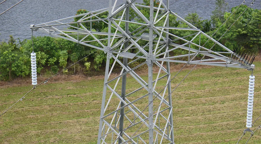
This case study looks at performance of a bespoke line design arrangement presently in service in Powerlink’s network that features double circuit vertical construction but with a dual voltage two circuit arrangement (see Fig. 1). Circuit A (left side) features a 132 kV insulation design, while circuit B features a 275 kV insulation design.
This asset was initially commissioned with both circuits at 132 kV. When operational triggers arose, Circuit B would migrate to 275 kV operation with minimal physical asset changes on transmission structures themselves. The line was built in several stages starting from 2008. In its final configuration, when Circuit B was energized at 275 kV, it would reach a length of 350 km.
The 132 kV circuit was configured to form segments of shorter individual circuit length since this side of the structure was routed into several intermediate 132 kV substations alongside the 275 kV circuit in its ultimate configuration.
From the time of initial commissioning with double circuit 132 kV operation, performance was extremely reliable. The line operated in a staged approach with this configuration commencing in 2008 for 13 years before Circuit B was commissioned in 2021 at 275 kV. Table 1 summarizes the insulation pollution design characteristics for the double circuit line.
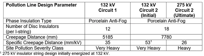
Once Circuit 2 was energized at 275 kV, the adjusted pollution design particulars are also outlined in Table 1. From the time of energization in the new dual voltage configuration, pollution outage rate for the 275 kV circuit failed to meet expectations which required an urgent investigation into performance issues and related modes of flashover.
To better understand the performance issues at hand, it is worth revisiting the basis for design of transmission line assets at the time this asset was upgraded to 275 kV in 2021.

Legacy Pollution Design Standards & Insulator Selection
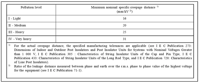
Tower designs for a dual voltage configuration commenced at Powerlink prior to 2008. Since the line was to be constructed in stages, a tower family design was developed for the first stage but then formed the basis for all structures used for the remaining stages. Pollution design standards for transmission lines at the time were defined by AS 4436, underwritten by the 1986 version of IEC 815 (as outlined in Table 2).
At this point, insulation pollution design in Queensland was qualitative in nature and highly dependent on experience based on asset performance of similar transmission lines located in the same region.
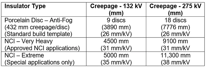
By 2008, templated pollution design for line insulation for porcelain, glass and NCIs had become standardized (see Table 3). Application of such pollution design allowed standardization of design assemblies across the network and facilitated logistics and spares planning aimed at minimizing insulator variants stored in the warehouse. Moreover, NCI coupling dimensions were designed to match those for templated porcelain disc solutions.
Tower designs and geometric development considerations for the new dual voltage asset were based on the higher operating voltage, i.e. 275 kV and correspondingly used to determine both cross-arm dimensions and vertical phase spacing. Insulator coupling distance assumptions, selected from the largest dimension of either the porcelain disc insulator assembly or the standard NCI application, was assumed for the development of electrical clearances for the suspension ‘I’ string configuration. Insulator string lengths were based on historical performance of nearby existing assets, some of which had encountered issues with elevated outage rates.
Unfortunately, there was only limited operating experience available at the time for the 275 kV voltage level in this asset locality. Therefore, a more global view of expected performance was considered. This was based on good operating experience with 18-disc assemblies (26 mm/kV) used since the mid-1990s for a large proportion of lines insulated at this SCD level. Given that bulk transmission lines were no longer delivered with NCIs by 2008, disc insulators were the default option implemented for the design of each section of line.
For 132 kV designs in this area, there was wider experience and associated performance data. For example, observations showed that existing 132 kV assets near the new transmission line had not been performing well. Specifically, lines with 9 normal profile insulators (16 mm/kV) in the vicinity experienced elevated outage modes linked to pollution in combination with bird guano or streamer faults from nesting species.
Development of suitable tower geometry for the new line therefore considered maximum coupling distance equivalent to 18 porcelain disc insulators along with the pollution design parameters as outlined in Table 1. Since limiting clearance was established by the 18-disc 275 kV I-string assembly, longer 132 kV strings seemed straightforward for the lower voltage circuit without penalizing tower structural design. This explains why 12 anti-fog insulators were adopted (as per Table 1) instead of the standard 9-disc anti-fog assemblies in place at the time (as defined in Table 3). This was undertaken pre-emptively for the 132 kV circuit while the 275 kV template was adopted to avoid penalizing tower design sizing in terms of increased height and weight.
Emerging Pollution Performance Issues
Fig. 2 shows the incidence of transient outages after commissioning of Circuit B from 132 kV to 275 kV which saw 11 transient faults in the space of 14 months after changeover. As normal, field patrols were immediately scheduled to categorize and rectify the faults.
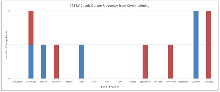
The post-event patrols as well as engineering assessment of outage data suggested almost a 50/50 split for the cause of the faults. There were no storms or lightning events in the outage vicinity and the 50/50 split was determined to be due to:
1. Roosting birds, with nests on affected towers and guano on or near insulator assemblies
Correlating faults to time of day indicated that most occurred either early morning or late afternoon. This is consistent with bird flight activity suggesting bird streamer faults.
2. Faults unrelated to bird activity and correlated along recurring specific locations of the asset
Storms were not noted in the vicinity at the time of faults and data from local weather stations indicated these coincided with factors such as:
i. 100% humidity;
ii. High dew point;
iii. Faults occurring in the middle of the night.
For both suspected bird related outages (summarized above in 1.) and pollution-initiated faults (summarized in 2,) outages occurred only on the 275 kV circuit B. No outages were recorded on the 132 kV circuit A during the 14-month period of interest. This behaviour was understandable in terms of notable design factors, including:
a) large airgaps for the 132 kV circuit on a structure with 275 kV optimized clearances;
b) increased string lengths of 12 insulators instead of the more typical 9-disc templated anti-fog design;
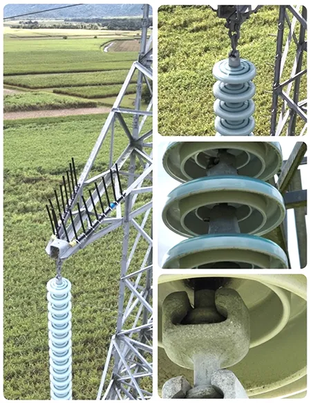
c) design of the string arrangements to provide symmetry to a structure with two differentially sized insulator strings. Fig. 3 shows the dual voltage differential insulation and airgap design for the asset. Conductor positions are symmetric across both circuits with equal heights above ground from use of extension links in the 132 kV hardware assembly. This extended offset design for the 132 kV string experienced no streamer faults on this side of structures along the entire line length.

Pollution Severity Assessment Based on IEC 60815
As highlighted in Fig. 2, outage mechanisms were categorized into two primary categories: bird related or pollution related, (based on engineering review and categorizing field patrol data from site).
Addressing bird related streamer faults did not require a site pollution severity (SPS) investigation but relied instead on placing bird nest and flight activity deterrents on cross-arms above the 275 kV circuit (see Fig. 3).
Resolving pollution related fault incidents required a different solution. These were not related to accumulation of guano on insulators and occurred mainly in a specific 50-km segment of the 350 km long asset. Fig. 4 shows this highly impacted line segment’s position location and unique topography.
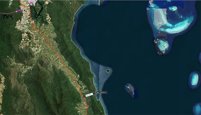
This section of line passes through Australia’s wettest region, typically receiving more than 4000 mm (168 in) of rain annually. It has distinct wet and dry seasons, the former driven by monsoonal weather from December to May. The term ‘dry season’ here could better be described as a ‘less wet’ since in the relatively dry window from June to November rainfall still exceeds 100 mm monthly. Humidity remains high all year, averaging between 80% and 90%.
The climate around this line segment is essentially that of a tropical rainforest, with stable, warm temperatures year-round. Summers average 31C in the warmest months to about 24C in cooler months. Average lows drop to 17C in cool months and 23C in warm months.
Such conditions lead to persistent condensation forming on surfaces of electrical insulation, combined with extended regular wetting due to seasonal trends in rainfall (as described above). This type of environment also supports formation of biological growths on the underside protected creepage for anti-fog profile disc insulators.
As shown in Fig. 4, the line also passes between two mountain ranges and across volcanic soil used for sugar cane plantations. Crop preparation, maintenance, and annual harvests generate dust and pollution, along with effects linked to fertilizer application. Nonetheless, transient outages from cane fires are not common since crops are cut without prior burning.
Although this line is over 4 km inland and shielded by mountains to the east, prevailing winds enable salt-laden air and, occasionally, conductive fog to travel up the valley. For example, salty air enters through a southern opening in the eastern formation where a river meets the ocean.
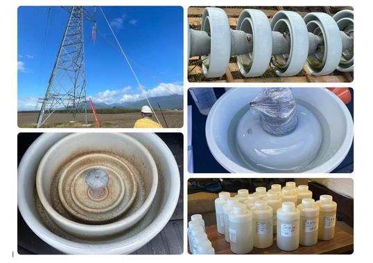
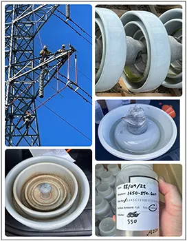
It was decided to conduct a site severity assessment in the vicinity of all recorded flashover locations along the entire line route. Given that affected structures were already equipped with new insulation to replace flashed porcelain units, sampling was performed on adjacent structures in accordance with methods outlined in IEC/TS 60815-1. This involved measuring accumulated conductive and non-soluble deposits on surfaces of insulators removed from service. It should be noted that this line is marked by absence of site specific or line pollution monitoring either by sensors or directional dust deposit gauges (DDDGs). Similarly, past leakage current data was also not available since this is not monitored at Powerlink.
To avoid cross-contamination, insulators were removed from service using live line methods and sampled on site to avoid transport and excess handling before measurement. Surfaces were sampled to determine ESDD. Suspended solutions were captured for transfer to an off-site laboratory to determine NSDD (as per IEC/TS 60815-1). Fig. 5 highlights this process.
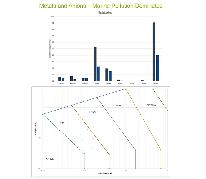
Fig. 6 is a record of the observations from site sampling at different locations. These showed that top surfaces were all naturally cleaned with the high rainfall as was to be expected and the predominate pollution accumulated in the protected bottom insulator surfaces. Result analysis indicated that all tested sites were medium or less pollution categories. Such results indicate the prevalence of Type B (liquid electrolyte) pollution effects in this portion of the transmission line due to the topography and weather conditions.
Options to Improve Pollution Performance
As per Table 3, the default option for remediation whenever disc insulation demonstrates deficient performance would involve targeted deployment of NCIs. However, since outages had also occurred outside the 50 km zone of interest in Fig. 4, targeted replacement of insulation would need to involve a significant proportion of the line’s route and without the benefit of data from ESDD and NSDD sampling on every structure.
Due to the high duration of wetting in this region, coupled with high electrical stresses at 275 kV, it was felt that NCIs would offer only low life expectancy. This conclusion was based on benchmarked performance of NCIs from other Powerlink assets that obtained only 15 years of service life before rapid degradation to failure. Widespread replacement involving a large population of insulators with significantly lower life expectancy than disc insulators would be problematic from an asset lifecycle perspective.
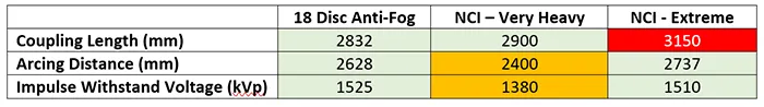
The option of replacing porcelain discs on this line with NCIs also presented other possible issues due to the lightning performance requirements for this asset, given the expected number of lightning strokes to the line per year across its length of 350 km. Table 4 demonstrates this issue where a re-insulation exercise is required to maintain the electrical withstand parameters for a string of disc insulators replaced by an NCI.
Moreover, addition of metal end fittings and corona rings to NCIs requires an associated increase in unit coupling length to match the arcing distance of the disc insulation string. Where arcing distances reduce, so too would lightning performance expected of the re-insulated transmission line. If arcing distances were matched, coupling distances between the NCI and disc string being replaced would also misalign and violate electrical and ground clearance restrictions for the structure geometry.
Given that application of NCIs was seen as not presenting an ideal re-insulation alternative, and with no possibility to increase length of the 18-disc anti-fog string to add creepage, factory-coated RTV glass from approved suppliers was considered the best option. Confidence in this technology was supported by reports of successful operating experience exceeding 20 years as well as defined applications in tropical environments from other countries.
However, there remained additional considerations to resolve as part of an effective RTV-coated insulator ‘onboarding’ process, including application trials and suitable training for maintenance staff.

Introducing RTV in Insulation Re-Design
Addressing reoccurring outages with RTV insulator replacement for such a long linear transmission asset represented a substantial challenge. For example, it would take much time to replace all the insulators across the entire feeder length.
For benchmarking, initial sampling locations as in Fig. 6 were expanded to further locations that had not experienced outages. Application of surface sampling across several representative microclimates and nearby coastal lines allowed a risk assessment to be performed. The goal was to prioritize and allocate resources from most critical to less critical locations for insulator replacement. Areas deemed low criticality were not replaced and maintained existing porcelain anti-fog insulators.
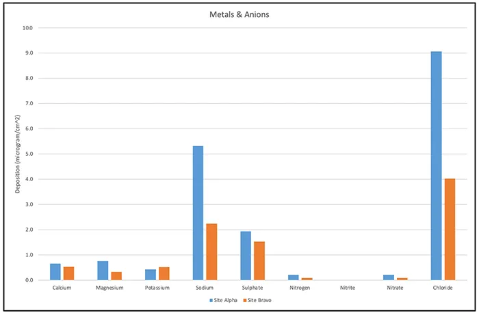
ESDD/NSDD sampling in combination with analysis of surface components (i.e. metals and anions as in Fig. 7) provided useful input into this risk assessment process. Recurring fault locations but with low ESDD and NSDD rankings suggested presence of Type B pollution and became prime candidates for initial RTV-coated re-insulation. Sampling also located several line segments with low to no recorded outage frequency but with sampled insulators still exhibiting a high NSDD to ESDD ratio. These observations demonstrated more candidate locations for application of RTV coated insulators. Several results in this exercise proved counterintuitive, such as where surface sampling from closely coupled line sections near the coast showed only low pollution contamination.
This sampling exercise also looked at addressing the impact of streamer faults and bird deterrent requirements on selected structures. Similarly, local knowledge from patrol crews as well as past structure and insulation inspections were used to identify presence of nests and guano.
The outcome of the sampling exercise was that approximately 19% of transmission line structures were recommended to be re-insulated with factory-coated RTV glass insulators. These insulators were only retrofitted to I-strings and I-string suspension configurations used on strain towers as pilot strings, i.e. all replacement insulators were in the vertical configuration. Horizontal strain insulator strings were not retrofitted since all outage locations identified involved vertical strings at 275 kV. Moreover, no RTV-coated insulator retrofits were performed along the 132 kV Circuit A.
A future roadmap for the 275 kV circuit could consider application of leakage current monitoring to aid future decision-making and to assess ongoing performance of both the RTV-coated insulator replacements and sections of line that were not involved in this first wave of re-insulation. Powerlink is therefore now actively following development of next generation sensors for application to lines in this region.
One key question that remained for specification of the RTV-coated replacement insulators was whether these should feature coating for top and bottom surfaces or whether partially coated (bottom only) disc insulators would be sufficient. Ultimately, two key criteria resulted in the recommendation to purchase only bottom coated units:
1. High rainfall, thus allowing for effective washing of unprotected creepage on the top of all insulators in all locations sampled;
2. The requirement that all replacement RTV strings must allow for live methods of installation. Restricting coatings to bottom surfaces offered less risk of damage to the coatings by rigging and tooling methods associated with insulated stick installation methods.
At the time of purchase, updating technical specifications was hampered by lack of industry guidance from international standards for factors such as approach to type-approval of factory coating method, coating manufacture and application technique, coating thickness and adhesion validation for large batches.
Change Management Process for Installation, Logistics & Handling
Powerlink performs a high proportion of insulator replacement tasks live. As a result, developing suitable methods to handle and install RTV coated insulators so as to minimize any damage to the coatings was deemed paramount.
As discussed, the section of 275 kV line to be re-insulated with coated disc insulators passes through Australia’s wettest locality. Coating manufacturers provide guidance for storage and handling of RTV material to ensure it enters service without damage that could compromise performance.
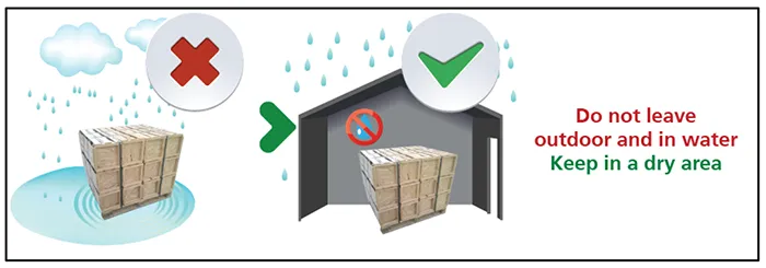
In this case, given that it was required to install some 10s of thousands of units in a persistently wet environment, thought had to be given on ensuring that the new coated insulators would be stored under dry conditions while awaiting installation. Similarly, it was also deemed vital to plan how best to stage them to installation sites in a controlled manner. This would avoid risk of moisture damage to storage crates that could also impact integrity of the coatings, as per supplier guidance (see Fig. 8).
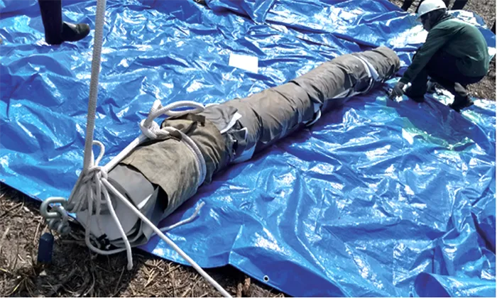
Moreover, installation instructions from suppliers often focus on de-energized handling of strings during installation. Fig. 9, for example, highlights one recommended treatment of RTV coated strings that have been wrapped for protection prior to installation. However, such measures may not be suitable for live installation.
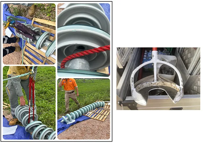
To deal with this, Powerlink organized field trials at its training facilities and test structures. Alternative handling, trial lifting and rigging techniques were simulated and practiced to determine the best approaches. This also ensured clear communication to maintenance teams about any existing techniques that may no longer be suitable when handing RTV-coated strings. Fig. 10, for example, illustrates that some methods used with live line ropes can cause damage even to bottom-only coated insulators. Therefore, adjusted tooling selection and updated approaches were required.
Performance Post Installation
An initial population of 30,000 RTV coated glass disc units entered service in 2022, representing about 19% of all structures on this 275 kV transmission circuit. Pollution-initiated outage events have not re-occurred on this line since this first wave of installation was completed in 2023. Meanwhile, there has been further periodic optimization of bird streamer prevention methods in response to observations made during feeder inspection patrols.
Spare RTV-coated insulators are being held in storage should future outages occur at structures on this circuit not yet covered by the re-insulation project. These insulators will then be deployed as replacements at faulted structures.
Targeted insulation washing may also be used in locations where no RTV-coated strings have yet been applied but where solid pollution types are observed during periodic visual inspections.
Conclusions
Factory-coated RTV glass discs are now an accepted and approved technology for network applications with specific pollution design concerns.
Given the tempering of past expectations at Powerlink for long-term performance of NCIs, factory-coated RTV disc insulators will now be triggered for default application in tropical environments (ahead of NCI technology options) as well as to address any site-specific high pollution issues.
Deployment of factory-coated RTV glass disc insulators at Powerlink has demonstrated clear advantages in mitigating pollution-related outages and enhancing reliability of an asset that was not performing in accordance with original design expectations.
Initial positive outcomes observed since their large-scale deployment -including absence of subsequent pollution outages – highlight the effectiveness of this technology, even in challenging environments such as this tropical Australian context.
Adopting RTV-coated insulators as a standard for tropical and heavily polluted sites in the Powerlink network offered an example of a strategic and evidence-based approach to asset management. By prioritizing such proven solutions tailored to specific operational risks, this network is now better positioned to optimize long-term performance and asset longevity.