The 400 kV Gutinas-Brasov overhead line runs past a mountainous area of Romania that has mostly rocky soil. Thick ice covers conductors during winter and in the past caused breakage of the shield wire such that it had to be dismantled in the most severely affected sections. Without shielding, these sections were left vulnerable to lightning strike. To reduce impact on reliability, a solution involving application of line surge arresters was selected for these sections.
The project was carried out in two stages. Experience during the first resulted in improvements during the second installation. Further improvements were later also applied to improve arrester safety. Compared to the situation before installation of arresters, which saw from 4 to 10 lightning induced outages per year, no outages were recorded over the following 10-year period.
This edited past contribution to INMR by engineers at Romanian TSO, Transelectrica, reviewed details of the project’s engineering as well as key lessons.

TLSA Technology
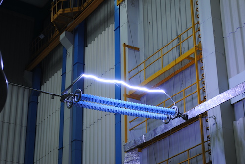
Shield wires have been installed on transmission lines in combination with good earthing to assure good lightning performance in areas where lightning impacts reliability of electricity supply. But shield wires can at times themselves become a liability such as if they ice up and sag or gallop, leading to risk of flashover between them and the phase conductors below. An alternative in such cases is application of transmission line surge arresters (TLSAs) in parallel with the insulator strings. While the traditional approach using shield wires has been to conduct a lightning strike to ground before flashover occurs, the line arrester approach involves conducting the lightning strike around the insulator string, without flashover in air. In the case of shield wire, low resistance earthing is necessary. But if arresters are applied to all insulator strings, performance no longer depends on earthing resistance (although some arrester manufacturers still recommend maximum values for resistance to earth).
There are several factors to consider when selecting TLSAs for any application. For example, arrester rating has to be coordinated with arresters at substations. The line arresters should be the same rating or higher so that they do not end up protecting the substation arresters. Moreover, line arresters have to be sized based on voltage as well as a line insulation evaluation. To avoid a problem of line lockout, arresters can be equipped with a frangible disconnector. The disconnector does not clear the fault current but rather allows successful re-closure after breaker operation. If an arrester fails and power frequency current passes through the disconnector, an explosive charge ignites, shattering the unit.
Sometimes, mechanical failure of disconnectors, unrelated to an arrester fault, produce a situation where an arrester is unnecessarily taken out of service. Another situation that can occur is when surge currents set off the explosive charge and cause a disconnect operation even though the arrester has successfully withstood the surge event.
Surge arresters for line voltages above 230 kV require grading rings to avoid corona and to maintain satisfactory voltage distribution along the MOV disks. Under icing conditions, galloping can cause torsional conductor oscillations at frequencies that excite the natural pendulum frequency of line arresters. Experience has shown that many TLSA failures can be linked to installation-related issues such as when connections to the energized conductor or grounded structure are exposed to static and dynamic loads that lead to fatigue and overloading. This can result in broken connections or possible arrester damage.

Project & Background
The 400 kV Gutinas-Brasov line, designed and erected during the early 1970s, runs 126 km and connects the Brasov and Gutinas substations. The line is equipped with two sub-conductors per phase, each ACSR 450/75 sq.mm, and crosses the East Carpati Mountains – a region where there is near constant ice build up on conductors during winter. Initially, the line was provided with two shield wires over its entire length. But due to frequent failures in two sections, i.e. Towers #94 to 100 and also between Towers #130 and 145, shield wires in both sections were dismantled in 1985. Moreover, the initial phase conductors on the line section from #94 to 100 were replaced by a single ACSR 973/228 sq. mm conductor. Line arresters were later installed to diminish outages of this line due to lightning.
Planning for the first stage began in 2005 and saw arresters mounted on Towers #130 to 145 a year later. The second stage of the project covered Towers #94 to 100 and was implemented in 2013. The solution adopted saw the polymeric-housed MOV line arresters connected with the ground pole to cross-arms and equipped with disconnectors between the active pole and the phase. This was intended to eliminate risk of arrester damage due to Aeolian vibrations as well as galloping that would introduce dynamic loads when arresters are installed under the phases. Arresters had to fulfill all requirements specified in IEC 60099 and also to meet minimum performance characteristics such as continuous operating voltage of 255 kV, residual voltage at switching impulse, withstand voltage at 50 Hz for1 minute, wet conditions of 2100 kVmax and energy dissipation of 9.0 kJ/kV. Another condition was that of the disconnecting device between the arrester’s bottom and the flexible connection to the phase. Before mounting, measurements of tower earthing had to be performed and, in cases where earthing resistance was below 25 ohms, improvements had to be performed.
First Stage Project
One of the factors in the decision to proceed with Phase 1 was the number of lightning related incidents reported between 2000 and 2005, which varied between 4 and 10 outages per year. Since this line was among the most important for the security of the Romanian power network, such high numbers of trip-outs provided sufficient incentive to search for a permanent solution. It was therefore decided to install TLSAs in parallel with each insulator string on line section #130 to 145, which had operated without ground wires, to protect against lightning.
To begin, existing suspension towers were replaced by heavy tension towers and the two phase ACSR 450/75 phase conductors were replaced by a single ACSR 973/228 sq.mm conductor. Surge arresters were then suspended from tower cross-arms and connected to the phases. The TLSAs were installed for all phases on Towers #131 to 138 as well as on all phases of Towers #140 to 142 and also on Tower #144. These were all towers equipped with suspension insulator strings. The arresters were connected in parallel with the suspension insulator strings and limited voltage surges across the line insulation by going into conduction at a voltage below the line insulation’s flashover voltage. Since Towers #139 and 143 were towers equipped with tension insulator strings, vertical lighting rods were installed on their peaks instead of installing line arresters. Measurements of earthing resistance showed good results, i.e. under 10 ohms, so no further improvement was needed.
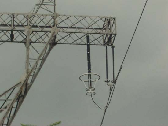
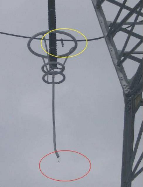
Upon completion of Phase 1, operating data on the Gutinas-Brasov line began to show an immediate decrease in reported outages. This confirmed that the protective strategy applied was both technically and economically justified, since, as numbers of outages decrease, so too does the cost of corrective maintenance. Nevertheless, there were still three incidents reported between 2006 and 2012 (i.e. Aug. 2007, Dec. 2009 and Feb 2011). Upon investigation, all were found to have been caused by weaknesses in arrester mechanical and/or electrical connections. It was also observed that sheds on the composite suspension strings had sustained damage due to hard knocking against arrester corona rings during asynchronous movements of insulator and arrester under wind. Damage was also observed on the corona protective tube covering the flexible connection between the bottom of the arrester and the phase.

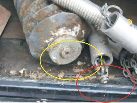
Analysis of these incidents revealed that several errors had occurred during the engineering design phase. For example, unsuitable locations had been chosen to suspend the arresters. Basically, there was insufficient distance between arrester and suspension insulator string to allow their independent movement under wind conditions and asynchronous balancing. In addition, selection and design of arrester components had been done without proper regard for the difficult conditions in the service area. This resulted in excessive rotation of the arrester around its axis, leading to the upper fixture unscrewing. The disconnector also had poor electrical and mechanical stability (as in Fig. 3) due to weak connection of the copper conductor in the clamps to the phase conductors (see Fig. 4).

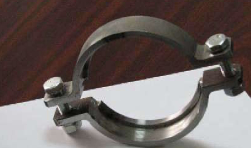
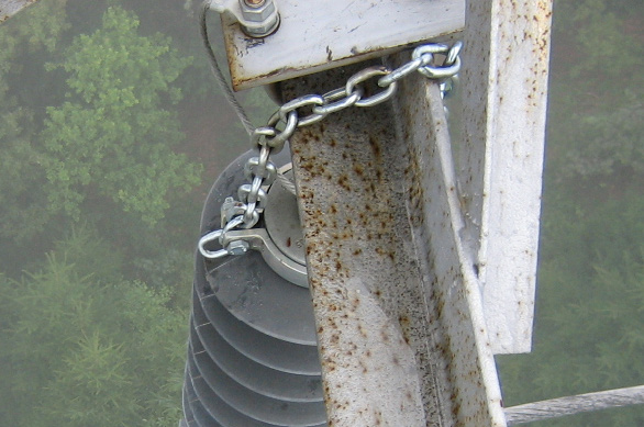
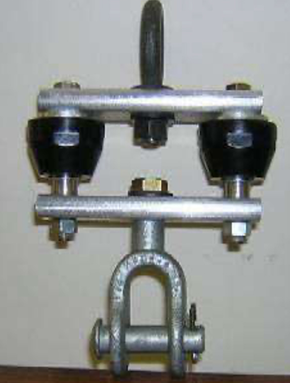
To avoid damage linked to excessive rotation of the arrester around its axis, 2 semi-collars (see Fig. 5) were later mounted on the upper fitting of the arrester, together with a chain to prevent accidental unscrewing (see Fig. 6). Moreover, to limit possible future damage, the disconnectors originally installed in Phase 1 were replaced by double disconnectors (see Fig. 7).
Solution Proposed for Second Stage
Based on experience from the first stage of the Project, leading to no lightning outages on the line between 2006 and 2011, it was decided to further reduce risk of outages by adopting the same solution on the line section from Towers #94 to 100 that had no shield wire. To avoid some of the problems experienced during the first stage, more precise design was needed, especially having enough distance between arresters and suspension strings so that the insulators would not be damaged by contact with the corona rings on arresters. Moreover, special consideration had to taken for tension Towers #94 and #100 with two possible solutions for mounting the arresters: the first by a rigid insulating connection to the live part of arrester (i.e. normal conditions) and the second to the live part of the line (i.e. conductors, clamps) and no rigid connection. The second alternative was chosen.
Clearance Criteria
Arrester locations had to be carefully selected based on analysis of clearances between live and grounded parts, under high wind as well as without wind. Asynchronous movement of the suspension insulator strings and arresters had to be considered as well. The dynamic pressure of the wind in the area is 45 daN/sq.m in accordance with the Romanian standard NTE 003/004/00. The minimum required distances in the air between the hot and grounded points are: 2900 mm in still air and 1000 mm in the case of maximum wind with no ice on conductors. Practically, these distances have to be observed between the arrester bottom terminal or its corona ring and the hot points as; conductors, clamps, etc. In the case of arrester installing on old lines it becomes almost impossible to respect the required distances in all the cases. To fulfill all the requirements is needed to perform important changes in the tower geometry involving long time line operation interruptions. Since the arresters have a deffect rate of 2. 10-5 only, it has to be assumed the risk of line operation interruption for a time of maximum 10 hours to allow the maintenance team to dismantle the deffected arrester.
Mechanical Criteria
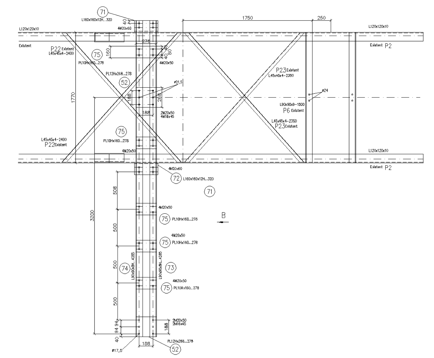
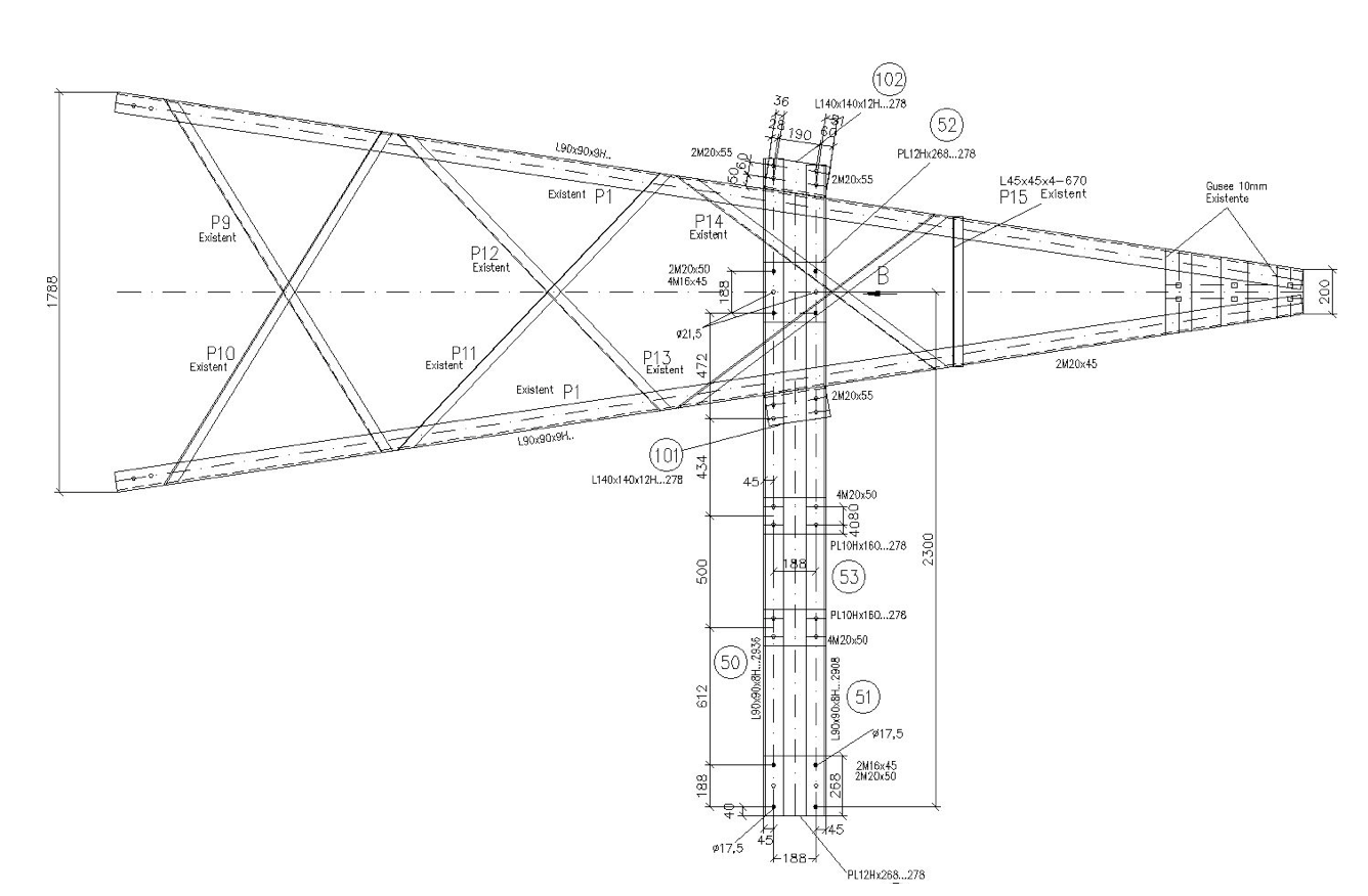
Since different cross-arms had to be mounted on the existing towers to allow installation of arresters at established distances from suspension insulator strings (either in the case of suspension towers or tension towers), tower elements had to be re-calculated taking into account the new forces and moments involved by adding more elements. The same arresters as those of the first stage were chosen, satisfying requirements of international standards such as: IEEE C62.22, IEC 60099, IEC 60694, IEC 60060 and IEEE 1243, corresponding to the nominal voltage of the system, i.e. 400 kV. The arresters had polymeric insulation and were provided with disconnectors.

Arrester Positioning
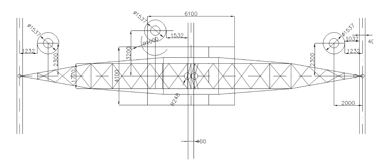
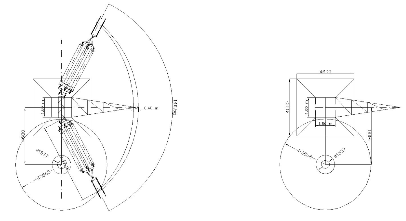
Arrester deflection angle under maximum wind was calculated taking into account its weight and that of the corona ring. Position of the maximum deflection point of the corona ring was found to be 2.338 m from the arrester’s vertical axis in still air. The suspension string could not be deflected either than in transverse plane on the line axis, in normal conditions and the maximum angle was 60°. In the case of suspension strings on jumpers, i.e. for towers 94 and 100 (which were monophase tension towers) this angle was 30°. In the case of asynchronous movement of arresters and suspension insulator strings, a horizontal distance of 2300 mm was needed between both axes taking into account the arrester’s deflection angle of 25°. Finally, for suspension towers, a longitudinal space between arrester axis and suspension string axis of 2300 mm had to be considered. A transverse space of 2000 mm had to be considered as well. As such, in the case of damage to the arrester a distance of 1000 mm would still be kept between the bottom terminal (under ground voltage) and the ‘hot’ points of the phase, which is deemed satisfactory if there is no wind (see Figs. 8, 9, 10). Similar distances were considered (see Fig. 11) for the monophase towers. If the arrester failed, the distance between its bottom under ground voltage and the phase would be 1474 mm, thereby still allowing line operation assuming no wind or low wind velocity.
Improving Tower Earthing Resistance
Earthing resistances in the mentioned line section were measured and the results over 25 ohms were: 95, 96, 97, 98- over the scale, 99- 25,43 and 25,39 ohms, 100- 2 ohms. Soil resistivity in the area was also measured, with the following findings by tower numbers: 94-95: 27.9 ohmm; 95-96: 501 ohmm; 96-97: 554 ohmm; 97-98: 1450 ohmm; 98-99: 127 ohmm; 99-100: 519 ohmm. In the case of soil resistivity exceeding 500 ohmm, allowable tower earthing resistance is a maximum of 30 ohms but, with the line arresters, maximum acceptable value was 25 ohms. Improvement to existing earthing by adding vertical rods was impossible due the hard rocky soil. Moreover, amplifying existing earthing by adding tape figures would lead to reduced efficiency. A ‘counterpoise earthing system’ was therefore proposed.
This sytem consisted of horizontal electrodes connected to the tower. These electrodes were radially laid in the soil around towers, with individual lengths less than maximum efficient length. All towers of the affected section had a horizontal electrode along the line route. This counterpoise system for towers 95 to 99 used galvanized steel tape of 40 x 4 mm. Effective lengths were 112 m for soil of 1500 ohms and 74 m for soil of 500 ohmm and all towers were electrically connected by this system.
No line outages were recorded in 2013 and 2014. But in January 2015 some flexible connections between arrester and phase were damaged, either at the phase end or at the arrester end. The connectors of both ends of the flexible copper conductor were therefore analyzed and it was observed that there was an inherent weak point for both connectors since the assembly contained only one nut. Vibrations during line operation meant that the probability of this nut unscrewing was unacceptably high. The solution to make it safer involved either using a double nut or having a splint through the bolt. While first solution was not feasible because insufficient bolt length, the second proved suitable.
Conclusions
Application of surge arresters on high voltage overhead lines is an excellent technical solution, especially in mountainous areas where shield wires cannot be installed because of ice forming on conductors. Romanian experience in this field showed excellent results from the point of view of eliminating outages due to lightning. Not a single lightning related outage was recorded on the 400 kV Gutinas-Brasov line during the period 2006 to 2015.
There were some problems after the first phase of application resulting in different types of damage. After analysis, it was determined that there were due to errors in design and installation, incorrect locations being chosen for the arresters to be suspended and manufacture of the arrester components without proper appreciation of local environmental conditions. All necessary improvements were then considered during the second stage of installation. Minor details may still have to be implemented during design and manufacture of these types of arresters to ensure better and safer operation.
References
[1] CIGRÉ Working Group 33.01, Guide to Procedures for Estimating the Lightning Performance of Transmission Lines, 1991.
[2] Oscar Kastrup et al., Lightning Performance Assessment with Line Arresters, Transmission and Distribution Conference, 1996.
[3] E. J. Tarasiewicz et al., Outline of Guide for Application of Transmission Line Surge Arresters—42 to 765 kV, EPRI Technical Update, October 2006
[4] Stelian Alexandru Gal et al. , Romanian Field Experience in Mounting and Exploitation of Line Arresters On High Voltage Overhead Electric Lines, Application of Line Surge Arresters in Power Distribution and Transmission Systems, CIGRE Colloquium CAVTAT, CROATIA 25-29 MAY. 2008
[5] S. Gal et al , Romanian Power Grid Company Install Lightning Protection to Improve the Reliability of the 400 kV System (Transmission and Distribution World Magazine, June 2010)
[6] Karthik Munukutla et al. A Practical Evaluation of Surge Arrester Placement for Transmission Line Lightning Protection, IEEE Transactions on Power Delivery, Vol. 25, 2010.
[7] G. Florea et al., Live-line surge arrester installing on a mountain section of the 400 kV Gutinas- Brasov o/h line (between towers 94-100), CIGRÉ Regional South-East European Conference October 10th – 12th 2012, Sibiu, Romania, (RSEEC 2012)