Since its founding 33-years ago, INMR has covered power line and substation projects on all continents and toured hundreds of factories for electrical equipment as well as most high voltage and high power laboratories worldwide. Such site visits resulted in thousands of photographs to support the resulting technical articles. Now, the photos are themselves the focus as are their individual ‘back stories’.
1998 Ice Storm Battered Power Network in Québec

The Back Story
In early January 1998, a huge mass of moisture from the Gulf of Mexico met a stationary system of cold air from Labrador, resulting in sustained freezing rain and ice pellets over a vast area of south-eastern Ontario, south-western Québec and the north-east U.S. The onslaught lasted nearly five days producing an accumulation of up to 80 mm of freezing rain in some places and leading to what then became the largest power disruption yet recorded in North America. Millions were affected, some for weeks. Equally significant, this outage occurred during the harsh regional winter and in areas where up to 80 per cent of inhabitants rely on electricity for heating.
![]()
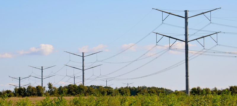
Most transmission towers used in Québec until that time were designed to bear up to 45 mm of radial ice – a load considered sufficiently conservative inasmuch as meteorologists claimed that a situation of excess freezing rain occurs only once in every 50 to 150 years. However, the combination of ice loading from the storm on these structures, which in some cases tripled their weight, and the ice-laden conductors brought down hundreds of transmission towers and tens of thousands of wood poles. In one unusual case, one 735 kV line built after 1973 survived the ice storm while a similar adjacent line built earlier was completely toppled. Although vertical capacity of the newer towers was probably less than for the older collapsed towers, balancing between components combined with anti-cascading structures succeeded in keeping this line line intact.


Most analysts of this Great Ice Storm of ‘98 agree that utilities must draw from experiences such as this to better prepare for these types of calamities. For example, Hydro-Québec officials acknowledged that the utility did not have any computer simulation on how to respond to such a catastrophic power failure. While the severe freezing rain that lashed the region for several days may have been without precedent in duration and intensity, these events could well become more common as the Earth experiences greater and greater climatic change.
±400 kV Line to Tibet Broke Records
The Back Story
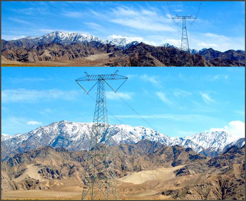
The 750 kV/400 kV Qinghai-Tibet Intertie has been one of China’s most ambitious network projects. Commissioned late in 2011, it connected with 750 kV AC lines running about 1500 km between the cities of Xining and Geermu, in central Qinghai Province. From the converter substation in Geermu, it continued as a 400 kV DC line to Tibet’s capital, Lhasa, more than 1000 km away.
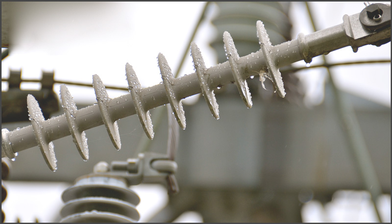
What made the ±400 kV line portion of this project so noteworthy was that it ranked among the world’s highest overhead transmission lines and also the longest HVDC line yet built at such altitudes. The line traverses terrain that averages 4500 m with the highest point reached at the 5300 m mountain pass at Tanggula. Apart from the obvious construction challenges across the vast, rugged Qinghai-Tibet plateau under extreme cold, permafrost, high UV and fragile local ecosystems, altitude impacted factors such as corona as well as electro-magnetic field. Designing the most suitable line insulators for this environment and meeting performance requirements of external insulation on HV equipment also proved demanding.
Overcoming risk of reduced hydrophobicity of silicone rubber under persistent cold temperatures required developing the most suitable shed geometry given the line’s pollution environment. The insulators ultimately selected have three different shed diameters: small, mid-size and large, each separated by a distance of 40 mm along the shank and in a configuration where there is a small shed on either side of both the mid-size and the large sheds. As such, the distance between any two consecutive large sheds amounts to 160 mm, less than the 180 mm spacing normally required in China for UHV applications.
Minimalist Towers for Dutch Power Grid
The Back Story
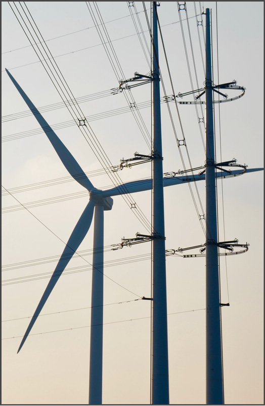
The Netherlands is a place where expanses of unused land are rare. In such an environment overhead transmission lines are not only unwelcome from a visual perspective but also subject to close scrutiny in terms of how they might affect the health of those nearby.
It was with these constraints in mind that engineers at TenneT, the country’s grid operator, embarked on an ambitious project to apply a concept for new 380 kV lines based on steel poles and braced line post insulators in place of conventional lattice towers. Key considerations from the outset were low visual impact as well as reduced magnetic field so as to significantly reduce the line’s required corridor.
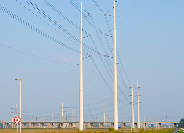
Finding a pylon that would meet architectural considerations of being aesthetic and minimalistic and at the same time not too costly proved a challenge. The goal was therefore to find some optimal balance between keeping the footing as small as possible to satisfy the criterion of minimalism while also respecting the fact that material and construction costs would be going up. At the same time, bending under wind loading, especially for angle structures, had to be within acceptable limits to keep them pleasing to the eye.
Another key element of the Wintrack design revolved around selection of insulators, which are all silicone rubber type. A key consideration when it came to these configurations was effective grading to ensure that maximum field stress along the insulator would always be less than 2.5 kV/cm, even lower than the 4.1 mm/kV recommended at the time by EPRI. This meant a great deal of shielding and required a double grading ring designed by the insulator supplier. This design criterion was intended to ensure the longest possible service life with minimal risk of erosion of the housing due to corona. In the end, Wintrack’s cost per km was about 1½ times higher than would be required for traditional lines. But here classical design was not an alternative.
Insulator Pollution Monitoring in Kalahari Desert
The Back Story
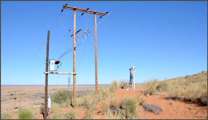
Few factors more influence performance and life expectancy of insulators than the service conditions where they are installed. Knowing the levels of pollutants that deposit onto insulators during the course of a year is therefore the best way for engineers to quantify and plan for the stresses that will affect reliability of overhead lines and substations. One utility that has suffered from recurring pollution flashovers over the years is South Africa’s Eskom – among the largest power companies in the world. With a vast network operating under the effects of coastal and industrial pollution as well as periodic brush fires, Eskom has for decades invested in monitoring its service environment using a far-flung network of substations and other sites where directional dust deposit gauges (DDDGs) as well as strings of reference glass insulators are installed.
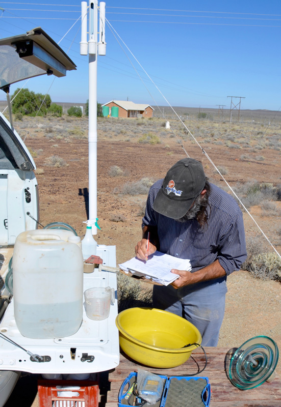
The standard DDDG used by Eskom is comprised of four vertical tubes, each with a large slot of standard dimension cut into its sides and arranged to face all four directions on the compass. A removable cylindrical receptacle at the bottom of each tube collects all wind blown deposits that enter these slots. The volume of material collected in each receptacle depends on wind direction and is greatest when it blows directly into the slot and lowest when it comes from a perpendicular angle. This means that the DDDG also indicates from where contamination most impacts a particular substation and helps identify pollution sources of special concern. Readings are also taken of pollution accumulating on the surfaces of reference insulator strings composed of 7 standard glass shells and installed next to DDDG locations. Each disc in the string is analyzed at different time intervals with the top and bottom units functioning as ‘dummies’.

Constructing ±500 kV Line Under Extreme Cold
The Back Story
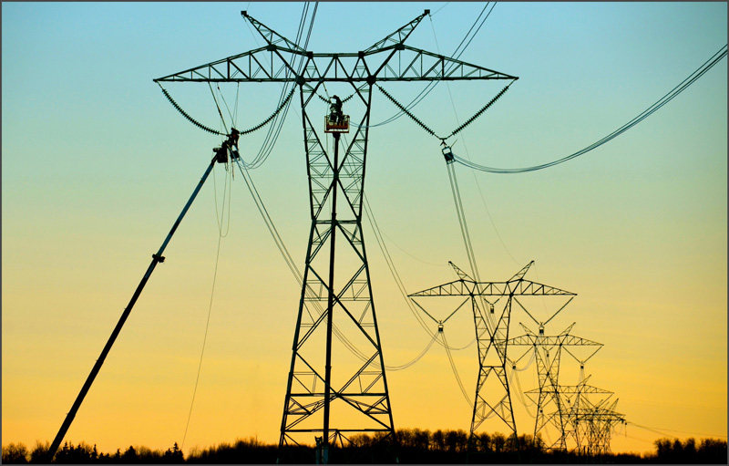
Construction at Alberta-based utility, AltaLink, is done year round even during the short days of winter when wind chills send temperatures plummeting and powerful winds can ground helicopters. To facilitate site access under such conditions, special mats made of rows of linked wooden poles allow passage of incoming heavy equipment to clear snow or to erect towers and mount insulators as well as line hardware. Conductor stringing is assisted by helicopter.
The ±500 kV WATL line provides a good example of construction proceeding even under difficult wintery conditions. This project replaced the alternative of a double circuit 500 kV AC line and is insulated with 34 standard profile glass bells per string for each pole and 7 on the neutral.
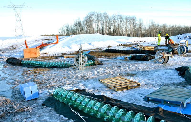
Insulators arriving and stored at the site are also factory-packed in closed boxes to prevent contaminants from being deposited during transport. The key is that when the insulator string is put up it is clean and free of road salt that may have fallen onto it and which might lead to tracking from the start.
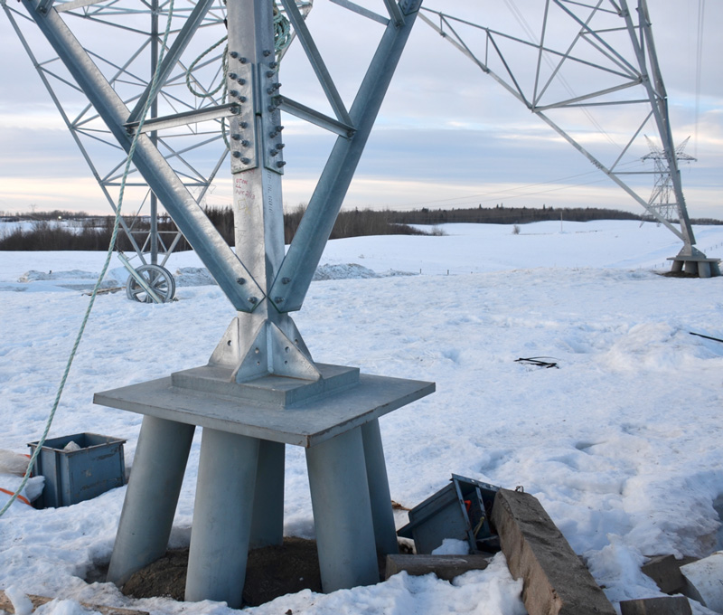
Every structure on WATL has been equipped with corona rings up to 3 m in diameter, depending on type, and which have been specially designed and tested by the supplier. Moreover, all line hardware, including conductor saddles and spacers, were required to be certified corona free in terms of smooth surfaces with no rough edges. The standard is that all hardware, including the armor rods that help damping and prevent fatigue failures, must be tested for cold weather shock loading. This is done to ensure that the steel always remains ductile, even at service temperatures down to -50°C.

Production of Porcelain Insulators
The Back Story
The past three decades have witnessed dramatic expansion of the Chinese power grid, with many large projects completed or underway across the country. For example, China’s average annual incremental generation capacity between 2000 and 2004 was 27 GW while the annual increment in installed capacity from 2005 to 2009 averaged 88.8 GW – about the same as the then total capacity of the United Kingdom.
Needless to say, this huge annual increase in electricity generation required a great deal of new transmission infrastructure This sustained investment helped fuel rapid growth within the domestic insulator industry, which has supplied the large majority of the country’s needs, both on lines and at substations. In fact, such has been the growth in demand that many new insulator factories had to be built while existing ones underwent significant expansion.
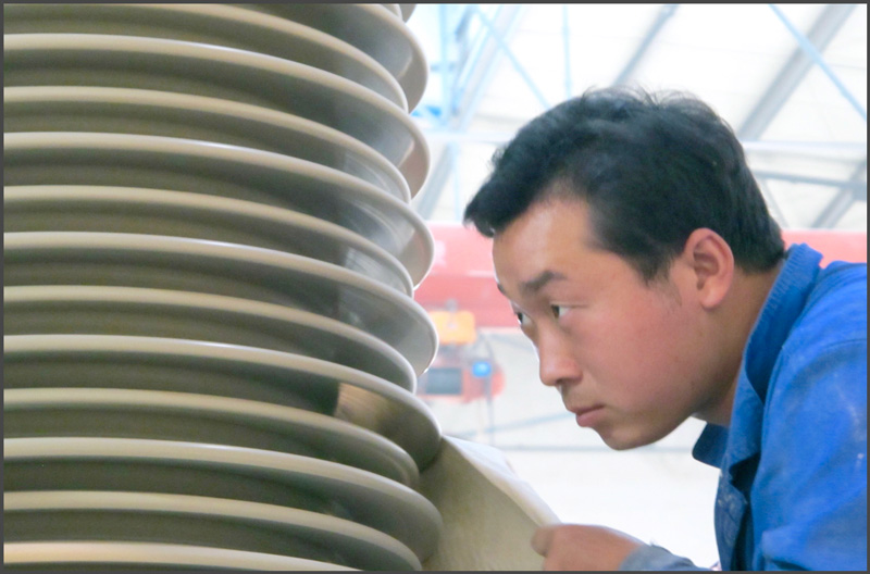
In the case of porcelain insulators, while a great deal of productivity enhancement has been realized by developments such as isostatic pressing of pugs and computer-controlled cutting tools, the human factor remains an essential element in final quality. The skills and dedication of each factory worker is therefore key to maintaining quality as well as yield.
Reducing Height of 400 kV Towers
The Back Story
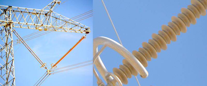
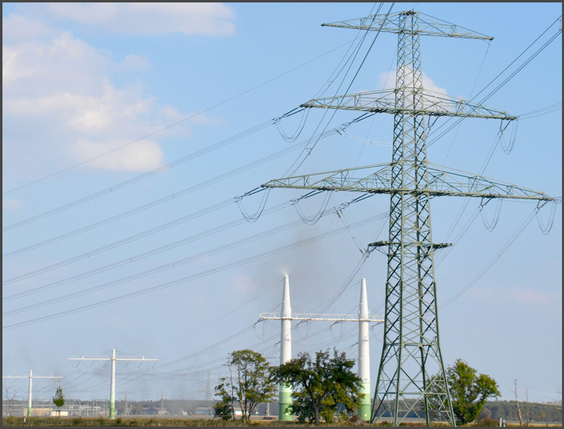
Research among the German public has shown that tower height is the decisive factor in perceived adverse environmental impact of proposed new power lines. The main technical characteristics of a new line design concept developed by TSO, 50 Hertz Transmission therefore aimed for significant reduction in tower height based on reducing conductor sag on 400 kV lines without compromising required minimum ground clearance of 12.5 m. Reduction of sag in spans was achieved through use of two additional steel support ropes in every conductor bundle. These galvanized steel wires are installed with high tension to attach the phase conductors to it. As a result, sag in each span is no longer defined by conductors but rather by the steel ropes with conductors attached.
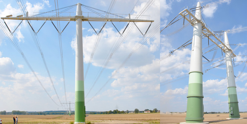
Due to the highly tensioned steel ropes and increased weight, resulting mechanical forces on tension and suspension towers are significantly higher than on conventional structures. To comply with these added forces, a complete re-design of towers proved necessary. Moreover, an essential additional goal for the new tower design was reduction of dimensions at the bottom. The suspension tower was eventually designed as a single tubular, conical steel pole with ring flange connections. The dead-end tower, by contrast, was designed as portal type, consisting of two tubular, conical steel poles supporting the cross-arm. Cross-arms consist of steel profiles connected to the tower top by steel tie rods. The resulting standard suspension tower has overall width of 38 m and height of 30 m. The standard tension tower has overall width of 36 m and height of 36 m.
Transition to Polymer-Housed Cutouts
![]()
FortisBC, a utility serving large areas of British Columbia, Canada, has experienced a history of failures of fuse cutouts made with porcelain housings. While pollution is rarely a concern in the interior of the province, wide temperature swings over the seasons impact how certain line components age. Summers are usually hot and dry while winters can be cold, often with substantial precipitation. This type of weather pattern has historically caused problems with fuse cutouts due to moisture penetration and subsequent cracking of the porcelain.
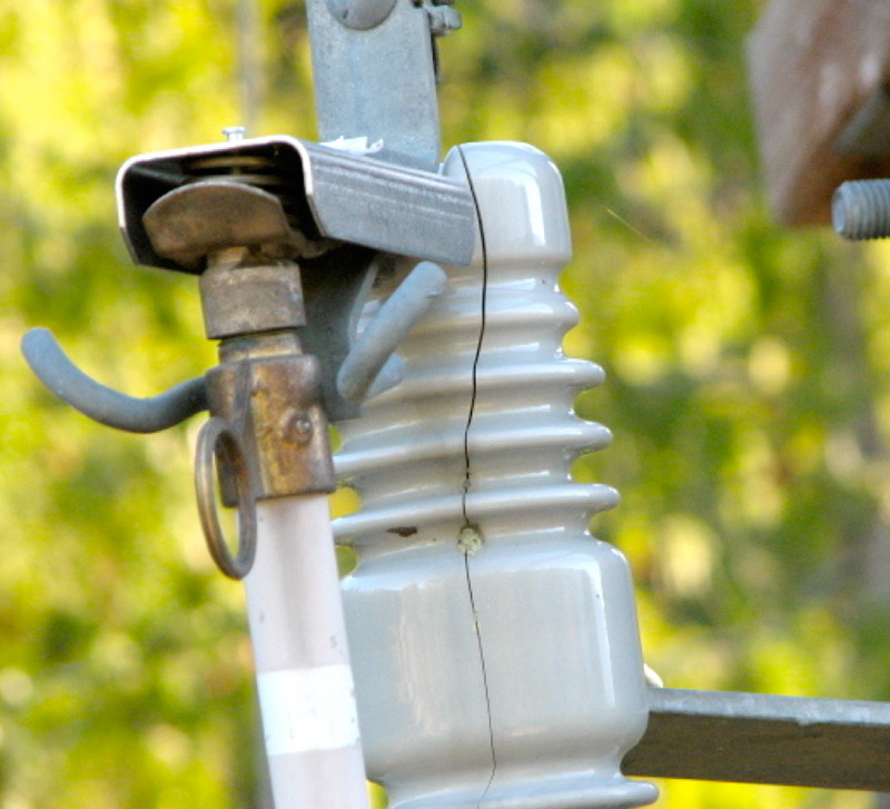
Investigation into the problem showed that of among the many thousands of cutouts installed on the distribution network, there were hundreds of documented cases of failure. Interestingly, this problem was found to be independent of time age since porcelain cutouts that had been in service only a few years were failing at about the same rate as much older cutouts. The conclusion was that these failures were due not only to ageing under local service conditions but also related to poor design and quality control problems during manufacture. Polymeric-housed cutouts are therefore perceived as an effective substitute and accordingly appreciated by line maintenance staff.
Structures Marked End of Lattice Towers
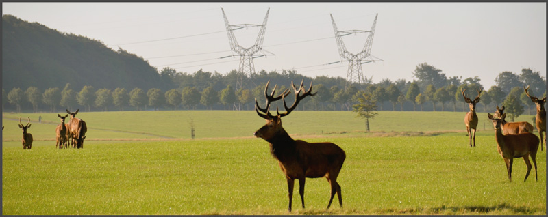
The meadows of the Jutland Peninsula are home to populations of deer stags, whose antlers might well have inspired the unique 400 kV lattice towers that connect this region with the rest of Denmark. But not long ago, this Scandinavian country became the first place where the lattice transmission tower is no longer accepted for any new construction. What made this development especially noteworthy is that Denmark is frontrunner in a trend that is already impacting a growing list of countries – overcoming public resistance to the building of new overhead lines. In this regard, rightly or wrongly, the lattice tower has become a symbol of the blemish that overhead lines sometimes impose on natural landscapes. This suggests that if power companies can find more aesthetically pleasing structures, there is reason to expect that the public will object far less.
The new double circuit 400 kV Kassø-Tejle line that runs northward along the Jutland Peninsula contributes to the goal of strengthening the interconnection between Germany and Denmark, and from there to Norway and Sweden. However, realizing this goal by means of another overhead line required overcoming strong objections by those who lived in this flat region of small farms and historic towns. The firm of industrial designers who developed the stylized structures eventually selected for this line – dubbed Eagle Pylons – aimed to convey “calm elegance” and allow a major 400 kV transmission line to blend into a scenic rural landscape.

Hydrophobicity at Work
It is fair to state that 30 years ago few in the field of power transmission and distribution had ever heard the term ‘hydrophobicity’.
From a service performance point of view, polymeric housing materials used on composite insulators and similar components should provide long-term hydrophobicity, rapid transfer of hydrophobic properties into the pollution layer and, for a service situation where there are stabilized surface discharges, good resistance to tracking and erosion.
One test method to evaluate hydrophobicity is the so-called Dynamic Drop Test. Like the Inclined Plane Test, it is also a material test and works in a similar way however with a different specimen orientation, stressed by voltage and an electrolyte that does not contain any wetting agent. Typically, the leakage current threshold is adjusted according to the required pass/fail criterion, while the number of drops can be counted by a photo sensor barrier. This equipment can even be combined with other devices used for erosion and tracking testing, all within one screened cabinet.
Bushings Fight Monumental Battle Against Pollution
The Back Story
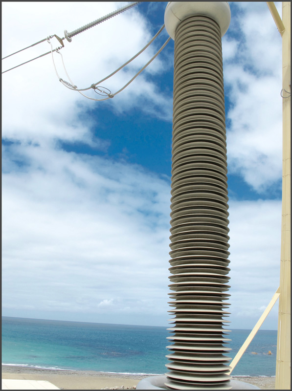
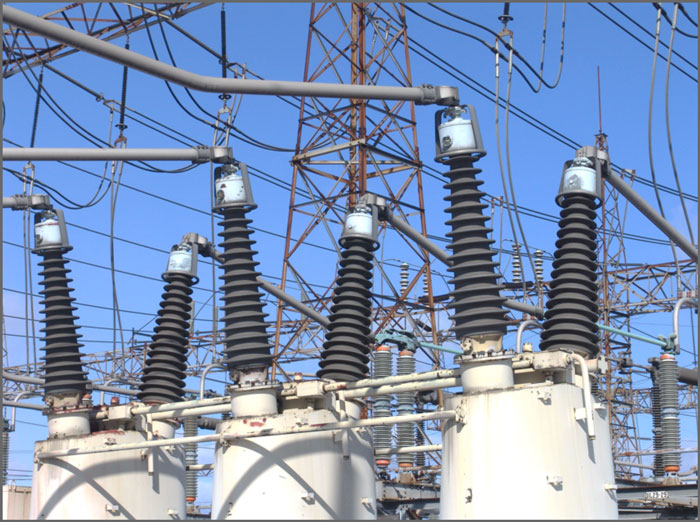
In the world of transmission & distribution there are a number of places whose pollution severity is of such a scale as to represent the pinnacle of challenges for electrical insulation. One of these is in beautiful, pastoral New Zealand. Almost from the instant it was built decades ago, the cable termination substation at a quiet inlet west of Wellington has preoccupied engineers and maintenance staff at Transpower, the TSO. The importance of the line that passes through this transition point only added to the urgency to win this battle. The ±350 kV Inter-Island tie links the 220 kV grids of the North and South Islands. Beginning to the south at the Benmore Hydroelectric Plant, the line travels 535 km to Fighting Bay on the shores of windy Cook Strait. It then crosses 40 km via undersea cables to Oteranga Bay, where it resumes overhead transmission for the remaining 35 km to the Haywards Converter Station.
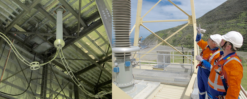
The site of the cable termination station at Oteranga Bay was selected because it offers the most preferential cable access but sits facing a stretch of open sea subject to steady north-south winds. These constant winds mean that salt crystals build up rapidly on the surface of insulation and, given the high humidity, can soon overwhelm even the best insulation. For years after construction of the original cable link during the 1960s, the station was open-air and the porcelain housings on the cable terminations had to be washed for up to 15 minutes every hour. In the late 1980s it was decided to enclose the terminations in a structure. While this effectively protected the porcelain terminations, the pollution battle was basically transferred to the two bushings that protrude vertically through the structure’s roof. The Pole 1 and Pole 2 bushings have each had their own history that helps explain why, though both are silicone-housed, the two have had different designs and dimensions as well as different service experience. For both, great importance was attached to select the optimal dimension and also proper location maintaining proper distribution of electric field so as to minimize corona and avoid ‘hoop stress’ rings that form on the insulator surface.

RTV Coatings Combat Cold Fog Pollution
The Back Story
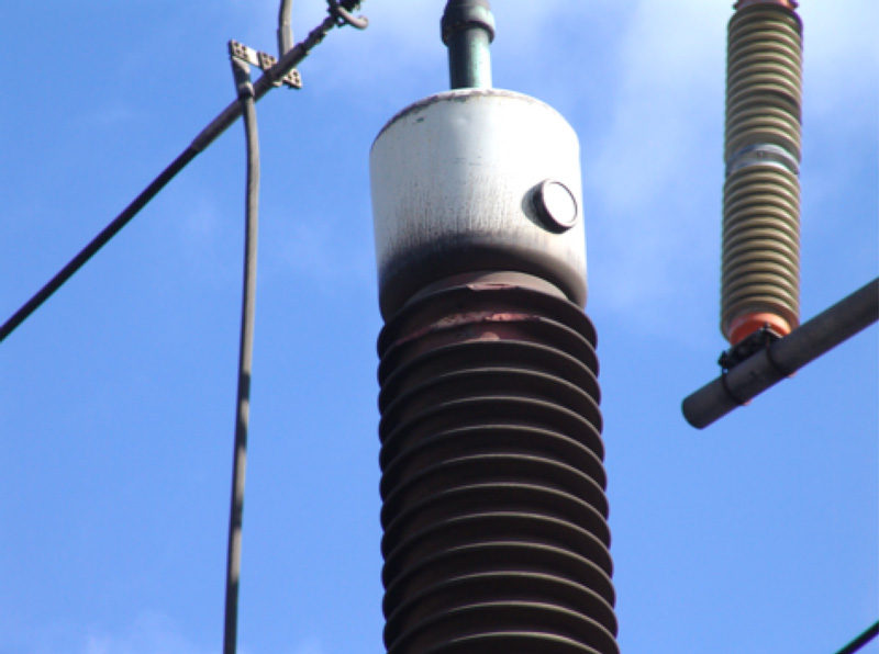
Most engineers in the power supply business can quickly identify locations in their networks that have been persistent trouble spots for outdoor insulation. In the case of Canadian utility, Hydro One, foremost among these used to be Hamilton Beach – a 230 kV station serving a concentrated industrial area. Located alongside steel and other plants, it also sits directly below a highway overpass that is salted during winter. Due to the combination of cold winter and moisture coming off nearby Lake Ontario, Hamilton Beach is also exposed to freezing rain such that salt contamination adheres to insulators in ice formations.
Over a 10-year period, measures to combat this pollution environment included high creepage insulation and washing up to 30 times per year. Yet problems of flashover affecting insulators and equipment continued. One day in Dec 1989, for example, over a million dollars worth of porcelain insulators were destroyed during a series of pollution flashovers. In 1991, there were 20 different phase-to-ground flashovers – all over a one-night period. By 1994, the situation with flashovers was so bad that all 230 kV beakers were put out of operation, effectively shutting down the station.
As a first step to resolving these problems, research using a special cold fog chamber was undertaken to study the particular flashover mechanism applicable to this location and to evaluate the relative performance of alternative remedial solutions. Among the countermeasures found to be most effective for this environment was application of resistive-graded porcelain insulators as well as coating insulators with RTV silicone. The RG porcelains offered good performance since heat generated from the continuous small leakage through the glaze prevents formation of the ice accretions that mixed with pollution. By contrast, use of hollow core composite insulators to combat pollution-related flashovers was found not to be as effective a solution.
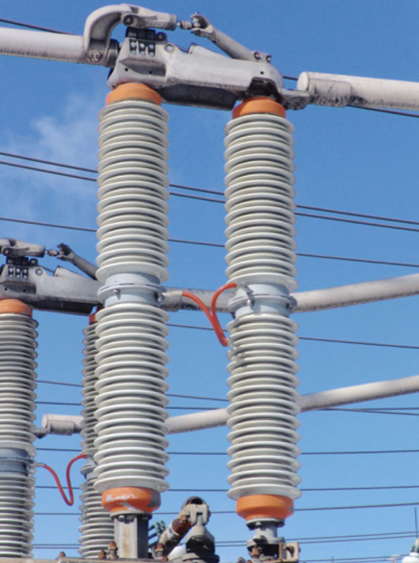
The second major remedial measure involved applying RTV silicone to apparatus such as bushings and cable terminations. These coatings were then pressure washed each year at 800-100 psi from a distance of about 4 to 5 m, typically just before winter. The unexpected finding was that 10 years later most of these bushings still had their original coatings and that these had maintained their hydrophobicity in spite of being exposed to local contaminants such as carbon black.

Hanging by a Thread
The Back Story
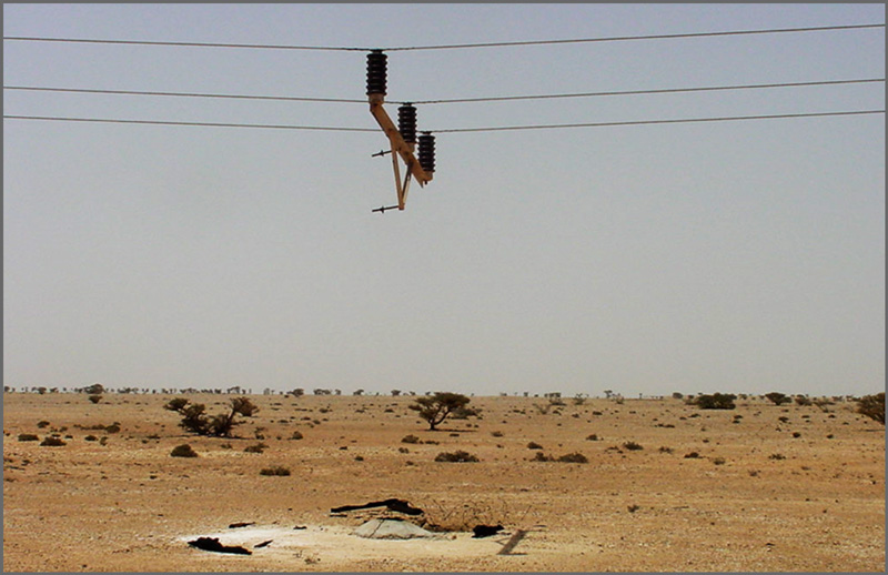
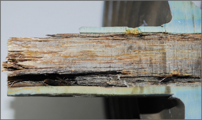
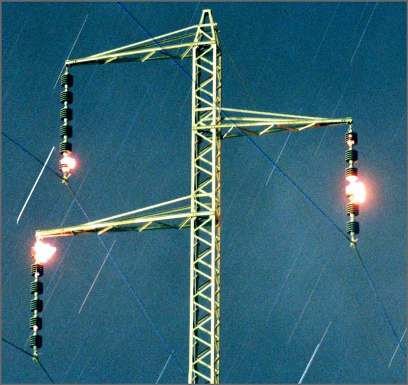
Pole failures in desert areas of Oman are triggered by excessive leakage currents on polluted insulators that have become wetted. The main pollution in this case is windblown calcium and quartz found in sand. Dampness comes from an increase in overnight humidity – especially during summer – leading to formation of dew. Around dawn, as surface moisture starts to evaporate, insulators are left with dry and wet patches along their surfaces. Given the service voltage, wet patches can be at different potential such that surface currents start to flow between them, visible at night as blue flashes.
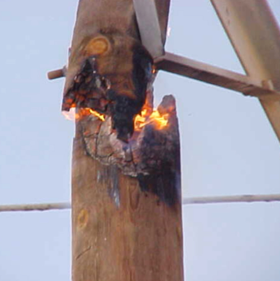
Since pollution levels are not uniform on each insulator, the cross-arm itself soon sees a rise in voltage as the current tries to reach earth by going down either the pole or the stay wire. Given the dry atmosphere, the pole’s cross-arm bolts tend to loosen due to pole shrinkage and thereby allow arcing to occur between bolt and cross-arm strut. This can then ignite the heartwood and a pole-top fire ensues.
Sometimes these die out, in which case the cross-arm bolt is usually left exposed at the center of a hollow burnt-out space. However, as the day heats up, the pole can smolder all the way to its base and leave the cross-arm hanging from the conductor.
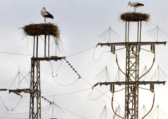
Birds and Power Structures
The Back Story
Service experience from various countries suggests that a high proportion of outages on overhead lines can be directly attributed to birds. Even though these types of outages are almost always characterized by successful automatic re-closure, utilities are still concerned. In the past, concern was due mainly to old oil circuit breakers that required maintenance after each cycle of about 15 operations. More recently, the worry is due to requirements for power quality and availability since many utilities set internal rules on average outages permitted each year per 100 km of line.
Any discussion of birds and power lines must first distinguish the situation for distribution voltages from that in the case of transmission. The two are vastly different problems requiring much different solutions. In the case of distribution systems, the central problem is electrocution of birds. Estimates of the numbers of birds killed each year are shocking. Especially dangerous are lines with vertically installed pin-type insulators because the conductor sits on the insulator, not below as in a suspension string.
What makes the situation the more tragic is that the threat posed to birds by distribution lines has been documented for years. Moreover, there is adequate knowledge on how to solve or least largely reduce the problem by insulating the conductors close to the tower using protective devices of different shape and design. The principal requirement for such devices, usually made of polymeric materials, is that they have a service life similar to that of the components they are intended to protect. In this regard, they must be resistant to deterioration from weathering and UV.
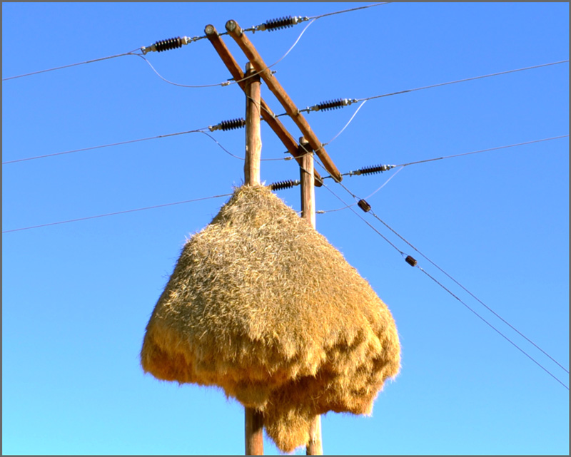
Fortunately, this image from the Kalahari Desert bordering Namibia captures a rare case where birds have built their massive nest with no obvious danger to them or to the line. Actually, these sociable weavers benefit from the power structure since it is one of the few elevated places in a flat expanse of desert that gives them protection from ground-based predators.
Not All Rod Fractures are Same
The Back Story
Each insulator technology has its own unique failure mode. In the case of toughened glass and porcelain insulators, these are spontaneous shattering and dielectric puncture, respectively. For composite line insulators, the most serious failure mechanism involves mechanical fracture of its core rod, which can result in sudden drop of conductor.
There is a tendency to automatically label all such failures as ‘brittle fracture’ since this specific failure mechanism has been widely reported and studied now for over 35 years. Typically, insulators experiencing this problem have failed at very low mechanical loads, after service for only months or years, and the fracture surface is characteristically flat and smooth. Fortunately, as a result of design improvements such as use of acid proof, boron-free rods and better field control to prevent corona damage to the housing, incidence of brittle facture has become very low in relation to the population of latest generation composite insulators now in service.
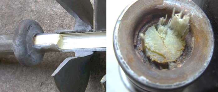
The incidence of another rod failure mode – decay-like fracture – is even lower than for brittle fracture but the consequences can be equally severe. While insulators experiencing this problem have also typically failed at low mechanical loads, the fracture surface in this case is not planar but ‘crisp’, like dead wood. Also, chalking has been found on surfaces of nearby sheds and on the glass fibers in the rod, separate from the resin matrix. In China, for example, this mode of failure has occurred mainly at 500 kV and it is important to note that the rate seems to have increased.
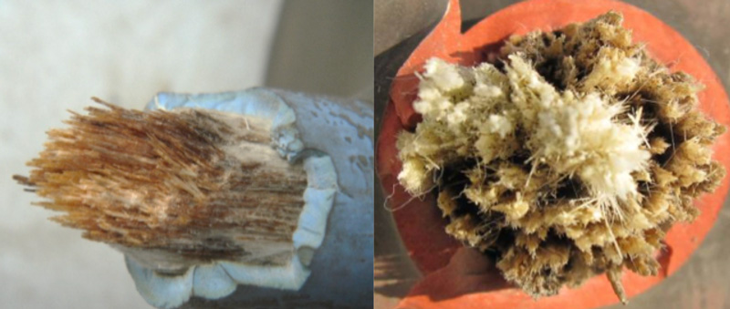
The mechanisms behind decay-like fracture are still not fully clear although it is known that these are often preceded by localized temperature rise and as such detectable by IR imaging. But this only helps in detection and offers no solution on how to prevent the problem.
Finally, it has been found that some composite insulators can fail in-service by another rod fracture mechanism that could easily be mislabelled ‘brittle fracture’. Research at the University of Denver showed that composite insulators can fail in-service even under low mechanical load if crimping deformations applied to the fittings are either excessive or improperly distributed. This type of failure is purely mechanical in nature and with no acid involved, even though the macro-failure characteristics closely resemble brittle fracture.
Squeezing In Another Line Required New Design & Insulators
The Back Story
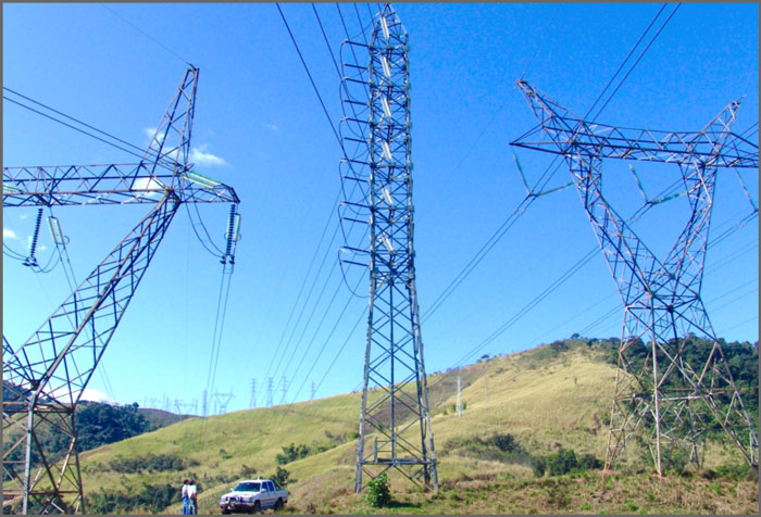
Pollution and vandalism have been the main factors behind application of composite insulators on transmission lines in Brazil. However, in 2002 engineers at Furnas in Rio de Janeiro were looking to add another transmission line in a narrow corridor between two existing 345 kV lines. Environmental restrictions did not allow this corridor to be expanded and therefore a compact design was deemed the only option.

The 50 km São José-Mage Line thus became the first transmission line at this utility to be equipped with composite insulators along its entire route. Line design engineers at Furnas had in the past been reluctant to ‘experiment’ with a relatively new insulator technology, especially since they recalled problems with original designs of composite insulators dating back to the early 1980s. But in this case, composite line posts were the most logical choice, allowing the new 138 kV line to be built within a much narrower corridor.
Porcelain Long Rods Stressed by Pollution
The Back Story
Insulators have traditionally been one of the major problem areas affecting reliability of the MV and HV overhead networks in Israel. For example, network management once estimated that about one in every four permanent faults on these networks were directly traceable to insulator failures with this proportion rising to nearly one in three if unexplained faults were also considered. Climatic conditions associated with the country’s sub-tropical location have been an important factor since the dry season lasts 8 months during which marine pollution, desert dust and industrial and agricultural contaminants accumulate on insulators. This pollution layer tends to be adhesive and is only partially cleaned away during the months of rain. To compound the problem, a large number of inferior porcelain insulators used to be installed on the network.
Over the years, Israel Electric tried to cope through over-insulation using insulators having as high as 38 mm/kV specific creepage as well as with special shed profiles offering extended creepage. However, neither changed the basic dynamics of the situation. Given the importance of these problems, a dedicated team of specialists was set up to systematically research insulator failures and to evaluate alternative solutions. In addition, an energized test station was set-up in the desert to monitor the comparative performance of different designs of insulators, arresters and other components.
Initial use of composite insulators in Israel began in 1987 with the original motivation for their selective installation being resistance to vandalism on distribution lines. Given this narrowly defined selection criterion, composite insulators were specified even though their life expectancy at the time was estimated at only about 15 years and in spite of a then acquisition cost which was higher than comparable ceramic insulators.
Subsequent years were marked by a growing understanding of the characteristics and features of composite insulators and this was accompanied by a consistent increase in their numbers installed on the network. The transition toward specification of composite insulators for all new line projects in Israel starting in the 1990s was therefore the outcome of a prolonged process of investigating the performance and financial benefits offered. Being a developed country located in a challenging sub-tropical climate only made these benefits that much more attractive.
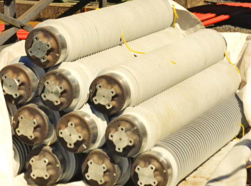
Handling Hollow Core Composite Insulators
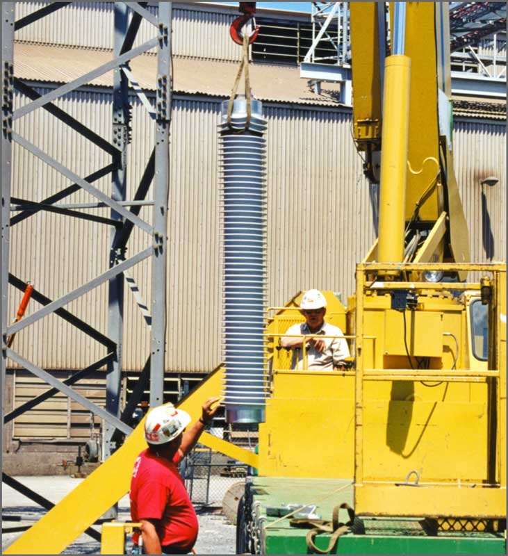
The Back Story
While composite hollow core insulators are now a mature option for electrical insulation applications, it is easy to forget that not long ago few knew how to handle or store these correctly. In fact, due to exaggerated initial claims about resilience of composite line insulators, there was the incorrect belief that these were virtually indestructible. Today, users have come to learn that composite hollow types must be lifted so as not to place undue mechanical stress directly on sheds. Neither should they be stacked such that sheds have to absorb excessive weight placed on them.
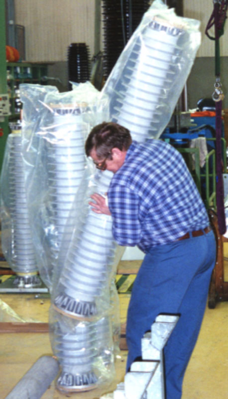
While proper handling in the field is always a concern, one of the factors that promoted immediate OEM interest in these insulators is their ease of handling in the factory.
Evaluating Composite UHV Line Insulators
The Back Story
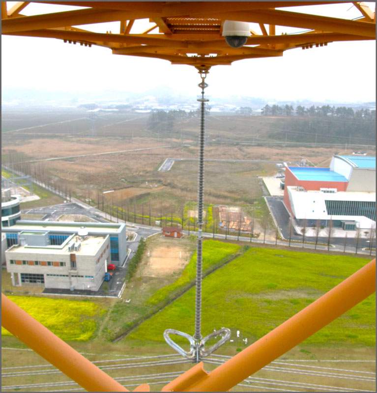
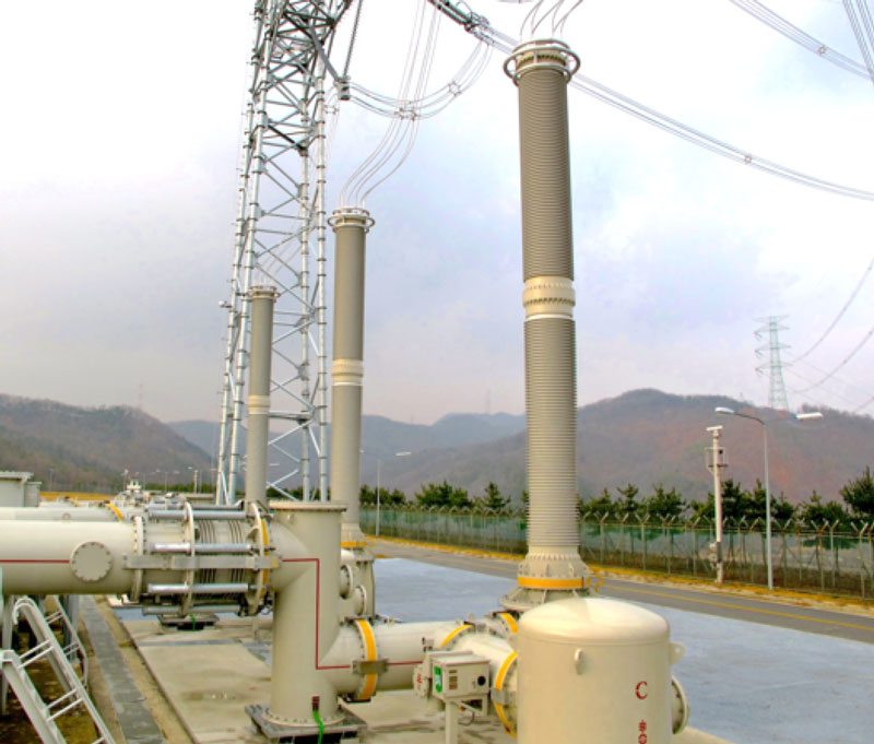
Korea Electric Power Corp. was one of the first electricity supply companies in the world to use composite insulator technology at UHV when it selected silicone-housed bushings for its 765 kV Shin Ansung GIS substation. Still, in spite of the success of this early installation, application of silicone insulators on transmission lines in Korea has lagged. Then, in 2010, looking to take advantage of lower procurement costs and to eliminate the need for periodic washing of lines, KEPCO decided to specify composite insulators for suspension applications on both its 154 kV and 345 kV networks. When it came to the critical 765 kV network, however, changeover in insulator technology required greater investigation. KEPCO is highly conservative and prides itself on operating among the most reliable electrical systems in the world, with an average outage time per customer of barely a few minutes per year. Given this, any new transmission technology tends to be studied extensively to ensure that it will not ultimately have a negative impact on reliability. Indeed, KEPCO evaluated composite insulators for more than two decades before reaching a decision to apply this technology at lower to middle level transmission voltages. Similarly, the design of Korea’s 765 kV grid was evaluated for 15 years before its first practical implementation in 2003.
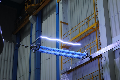
That is why in 2007 a program was started to evaluate the comparative performance and life expectancy of different designs of silicone insulators on UHV lines. While economic and technical considerations were considered important in final line design, the top priority was meeting the country’s strict environmental guidelines, which in the case of the UHV power highway included ground noise of less than 50 db and ground electric field of only 3.5 kV/m. Achieving such performance came about due to extensive research and testing of different tower and conductor configurations to identify those that optimize corona effects as well as electromagnetic fields. While 765 kV grids now exist in at least nine countries, the network in Korea is perhaps unique in terms of its application of double circuit lines at such a voltage level. The country is relatively small, leaving little choice but to rely on vertical array designs which double the energy carrying capability of a single right-of-way.
Virtually all of KEPCO’s development and testing of key line components such as towers, conductors, spacers and insulator assemblies has been conducted at a special test facility in Gochang, on the country’s western coast. Located only about a hundred meters from the seashore, the site is classified as medium pollution but, depending on winds, can also be exposed to heavier contamination. The original test program for these was carried out in co-operation with EPRI in the U.S. and concluded in 2010. During this period, insulators were inspected regularly for signs of corona, erosion and whitening while infrared inspection was conducted from the tower twice a year.
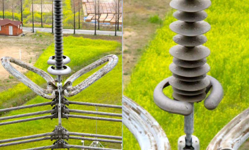
Among the reasons KEPCO first considered changeover in insulator technology on its 765 kV network was contamination flashover accidents. A program of annual live line washing of the porcelain cap & pin strings on these lines was started but this had to be done by helicopter since the height of towers did not permit sufficient water pressure needed for efficient cleaning if done from the ground.
Testing Performance of Composite Poles
The Back Story
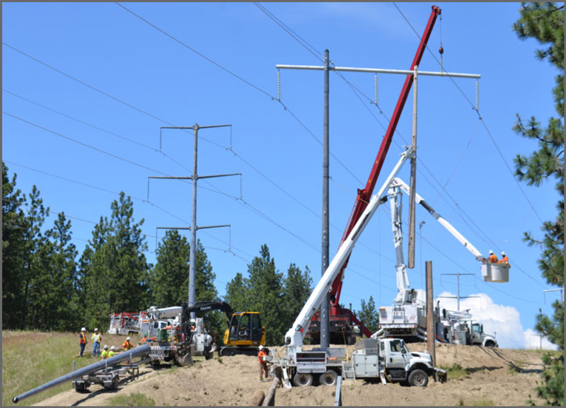
Wood pole framing is common on transmission networks throughout North America and indeed across the globe. However, while the typical service life of such poles is normally between 50 and 60 years, damage caused by various species of woodpeckers has, in extreme cases, required these structures to be replaced in only a fraction that time. Moreover, poles in affected line corridors may also need more frequent inspection since incidence of hole pecking occurs over a narrower time frame than most other problems. All this has made the activity of these birds a growing asset management challenge.

Maintenance practice at Canadian utility, FortisBC, has been that line inspection personnel assess the extent of any woodpecker damage to poles and decide whether an affected structure must be replaced or if more detailed inspection is required. Moreover, data on number of woodpecker holes is collected to determine whether the problem is stable or increasing, possibly due to factors related to climate change.
Moving to steel or concrete poles presents an obvious solution but comes with the challenge of transporting and erecting much heavier structures, often at remote sites that are not accessible by road. Both materials also offer less BIL than wood and this can impact an existing line’s electrical characteristics. Another option is composite fiberglass poles that are light and offer lower installation costs than steel or concrete alternatives. But such structures are generally much more costly than wood poles and their service life in this service area under high UV and periodic wetting still needs to be fully assessed. Yet another concern is that such structures will not prove as easy to climb as wood poles and therefore require a bucket truck for maintenance.