When two alternative technologies each complement the relative weakness of the other, combining them would seem logical. This article based on edited past contributions to INMR by Prof. Ravi S. Gorur, then at Arizona State University, and by Dr. Jens Lambrecht of Wacker Chemie in Germany addressed the benefits of coating ceramic insulators with silicone rubber material.


CLICK TO ENLARGE
CLICK TO ENLARGE
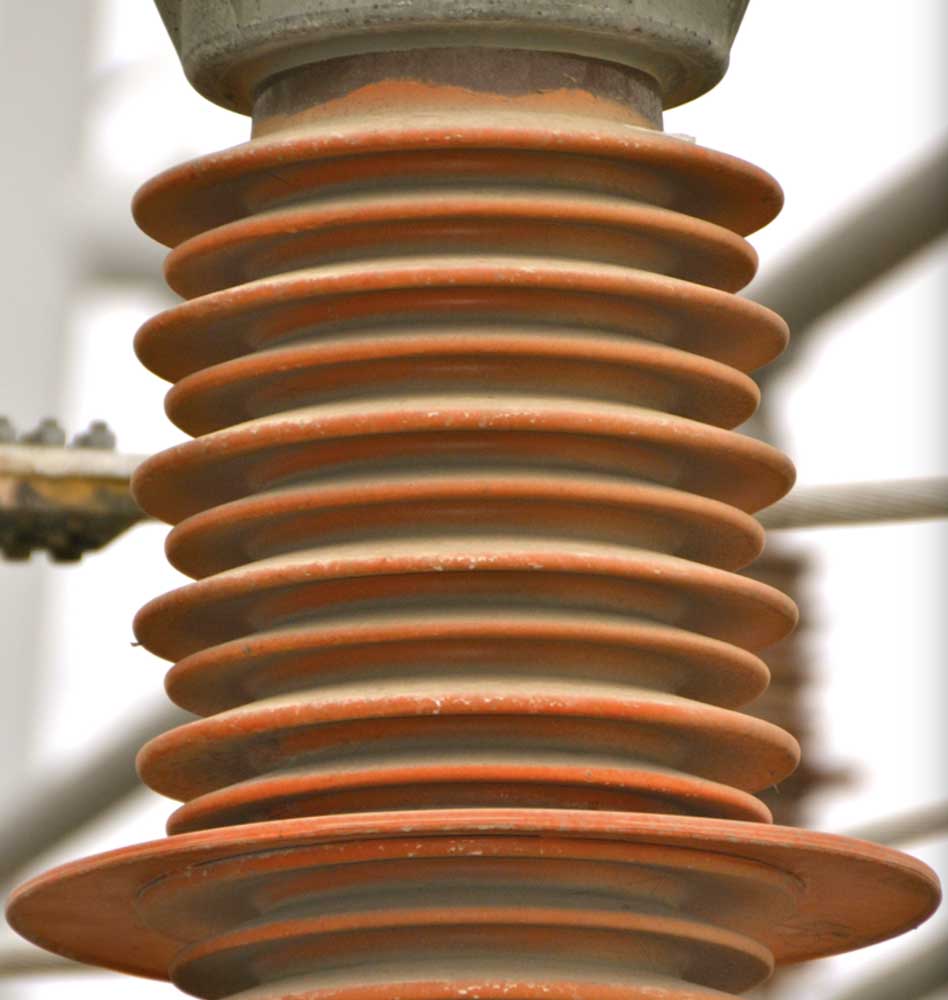
Porcelain and glass insulators are classified as ‘ceramic’ since each is based on silica. Both suffer from the same basic weakness – easy wettability and relatively poor contamination performance. Silicone composite insulators, by contrast, offer excellent contamination behavior but carry increased risk of permanent electrical or mechanical failure. Combining the two materials would therefore seem a perfect solution. Indeed, application of RTV silicone coatings to porcelain began at substations many years ago and has enjoyed much success. But, while growing, this practice has yet to achieve the same rate of application in the case of overhead line insulators. One major obstacle has been procurement cost since coated insulators are more costly than either ceramic or composite insulators.
CLICK TO ENLARGE
Going back to the 1980s, RTV coatings were applied to porcelain insulators to resolve contamination flashover problems at AC and DC substations. Since these were often installed in the field, conditions could not always be controlled and there were problems such as wastage, overspray, poor surface preparation, uneven coating thickness and inadequate adhesion. Yet in spite of such problems service experience was regarded a success since the former need for periodic washing was eliminated while pollution flashover problems were controlled. For example, flashovers of HVDC wall bushings due to non-uniform wetting (since the converter station wall was preventing the bushing from being either fully dry or completely wet during rainfall) were basically eliminated. While perhaps this result could also have been achieved using greases and oils, RTV coatings really stood out due to their continued long-term hydrophobicity, despite accumulated contamination.

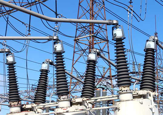
Indeed, existing substations, most of which still use primarily porcelain insulators, can realize significantly upgraded flashover performance through application of RTV silicone coatings. Not only do such coatings allow a reduction in annual maintenance costs but they also help extend equipment lifetime – especially for installations affected by heavy pollution.
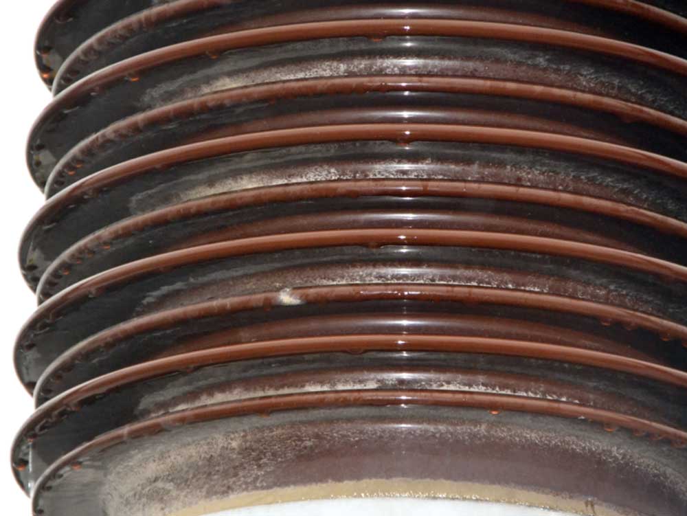
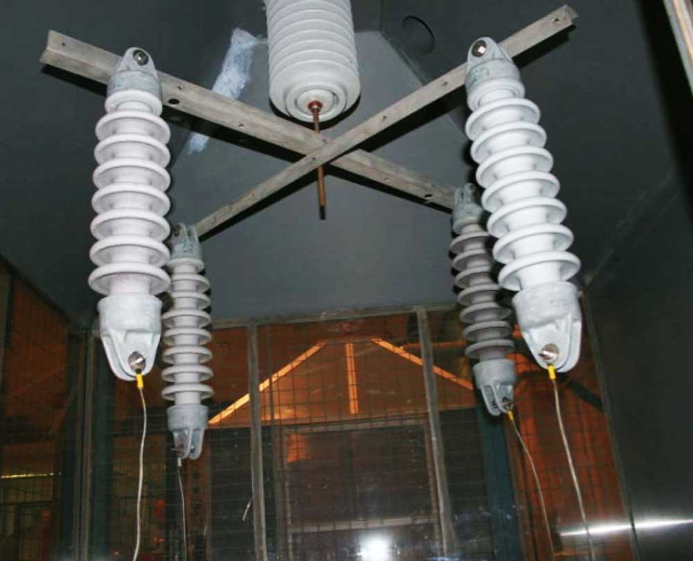
To demonstrate this, several years ago the HV Laboratory at Zittau/Görlitz University of Applied Sciences in Germany conducted special tests to provide greater insight into the flashover protection behaviour of coatings. The test specimens were medium voltage porcelain insulators with creepage of 700 mm, trunk and shed diameters of 60 mm and 122 mm respectively and dry arc distance of 355 mm. Test parameters followed those specified in IEC 62217, namely a test voltage of 20.3 kV, a specific stress on the creepage distance of 0.29 kV/cm and a fog conductivity equal to 6.7 mS/cm. Both insulator coatings tested (one of which was an ATH-enriched type) withstood the 1000-hour test with no evidence of erosion or tracking. Moreover, the typical leakage current recorded on the specimens over the test duration, under conductive fog and electrical stress, was never greater than 0.1 mA.
CLICK TO ENLARGE
Moreover, further testing was done to determine the remaining insulation capability of the insulator with the coating compared to the same insulator with no coating. In other words, would the coating still function as an effective pollution flashover suppressor once the test was over? In order to find out, both a ‘virgin’ coating and the already tested insulators were dipped into a slurry consisting of water, a wetting agent, fumed silica and sodium chloride to provide a wet conductive layer that would allow measuring pollution flashover voltage.

The flashover voltages of the insulators with the virgin coating and those whose coatings had completed the 1000 h salt-fog-test were virtually the same. While there were minor differences (e.g. at a layer conductivity of 6.7 mS/cm, the pollution flashover voltage of the new coating was 123.7 kV versus 120.3 kV for the coating after the salt fog test), these deviations would be regarded as negligible. The properties of the tested coatings, on the whole, remained basically unchanged. Stated another way, long-term stress in the salt fog test did not lead to a significant reduction in coating performance.
CLICK TO ENLARGE
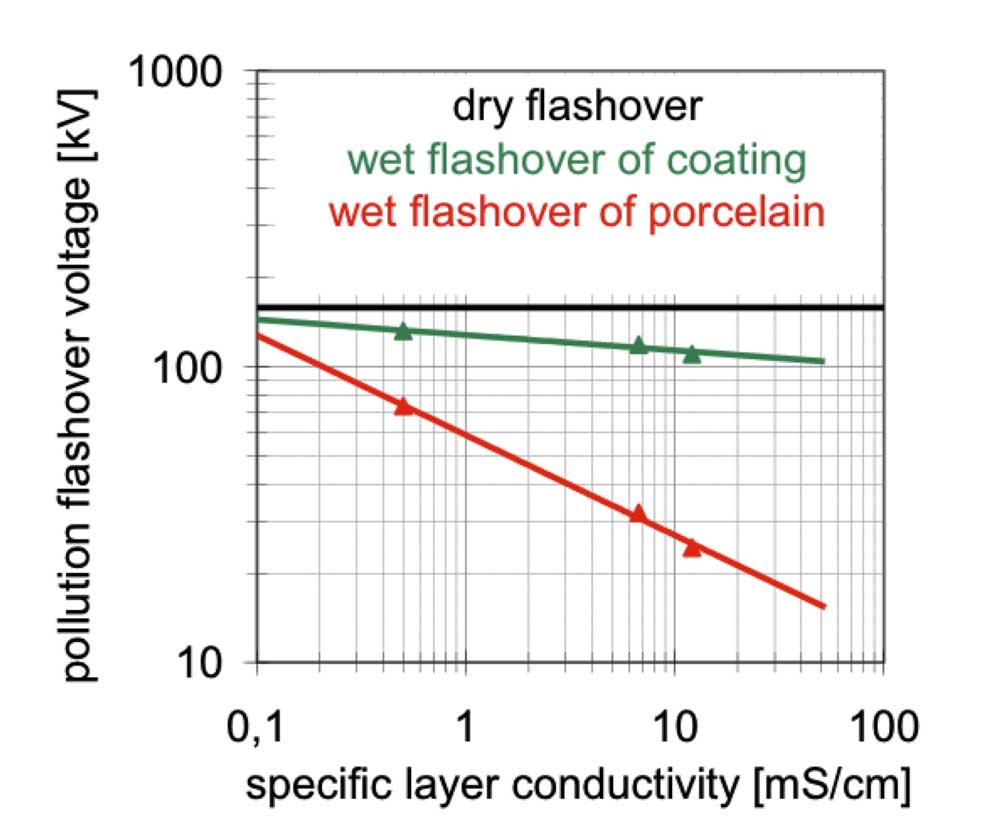
Finally, the pollution flashover performance of the stressed insulators having the silicone coating was compared to that of porcelains with no coating at all. Test readings of all insulators were then merged to create a more reliable database. Fig. 3 shows results at a glance. The pollution flashover voltage, Ufl, in dependence on layer conductivity, k, is given by the power function:
Ufl =C1 • Kc2
The graph therefore appears as a linear function in the double log plot. The results of this test demonstrate the benefit of the coating with regard to the pollution flashover voltage of an insulator and also that this benefit grows as layer conductivity increases. Based on the data, the pollution flashover voltage of the insulator tested at a layer conductivity of 50 mS/cm (i.e. that of sea water) can be estimated to be less than 20 kV. However, the same porcelain with a silicone coating will have a flashover voltage at this pollution level that is more than 5 times higher.

The message is clear. RTV silicone coatings assist maintenance departments worldwide to assure superior pollution performance of their porcelain-insulated substations. What might help convince even more users to adopt this solution is data that can better quantify the effectiveness of a coating over time. For example, as demonstrated, for any given system voltage RTV coated insulators will withstand higher levels of contamination than uncoated insulators. Demonstrating this in the laboratory when the coating is new is fairly easy. But what may also be needed is testing with insulators where the coating has been deliberately damaged to simulate improper installation, storage or handling. Even in such cases the contamination performance with a deteriorated coating would likely still be better than for uncoated porcelain since at least a portion of the insulator remains hydrophobic.
CLICK TO ENLARGE
The aspect of simulating coating performance after years in service is more complex. One could perhaps employ tricks such as using wetting agents during application of pollution in order to reduce hydrophobicity or performing the test on artificially contaminated insulators without allowing time for hydrophobicity to recover. Repeated measurements of flashover/withstand on a coated insulator would alter hydrophobicity unevenly along the insulator and lower flashover/withstand voltage with each successive trial. This might be one way to simulate coating condition after years of service. But which flashover value is most relevant and how to assess residual service life from such tests would keep researchers busy.
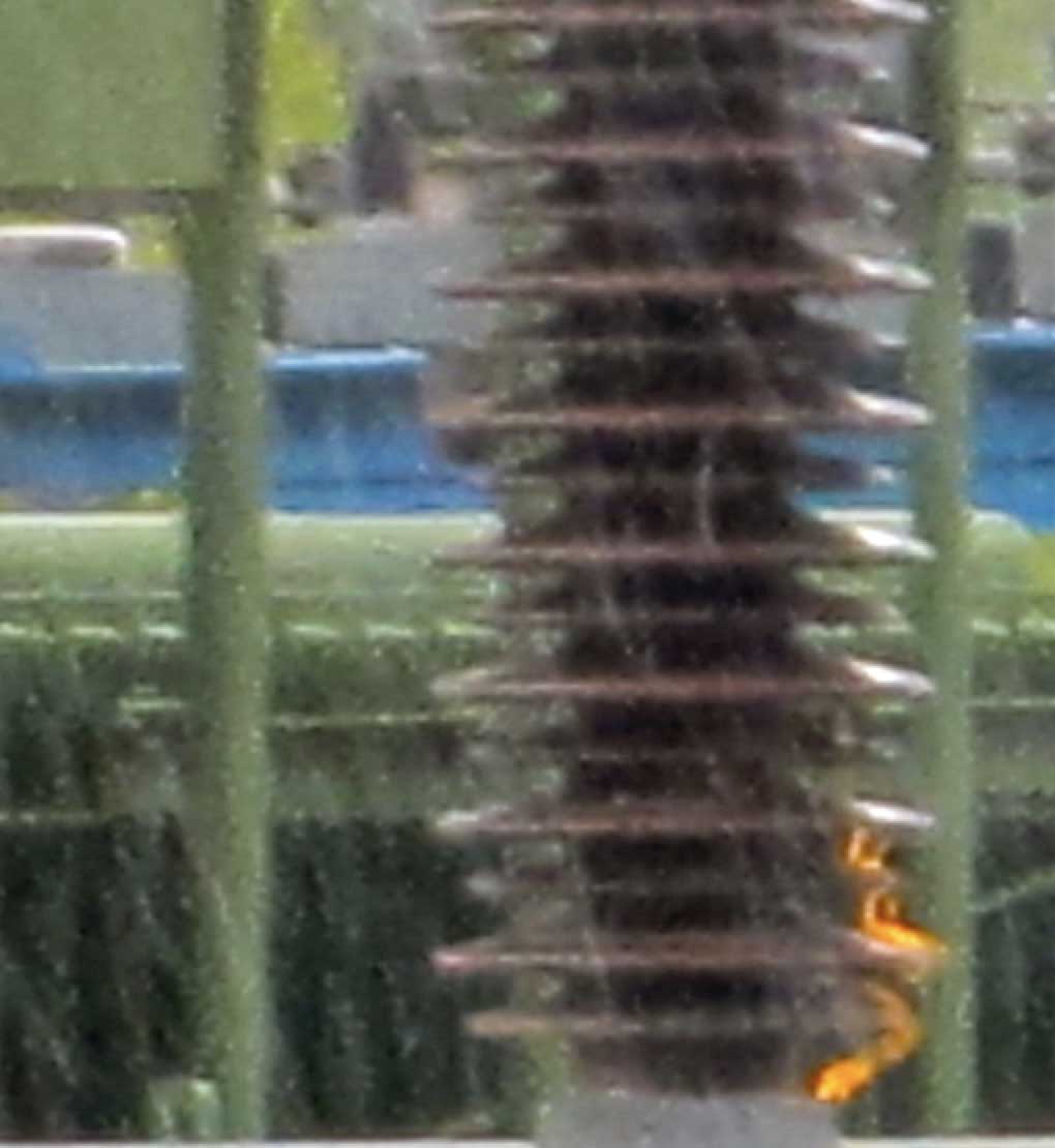
From a user perspective, one of the key questions is: when should coated insulators be cleaned or re-coated? One possible indicator in the case of substation insulation is audible noise. When a coating is new, noise due to corona is barely perceptible. As the coating becomes contaminated and hydrophobicity diminishes, one can expect an increase in surface discharge activity and therefore noise. But since this parameter is hard to quantify, it is still difficult to establish reliable criteria for maintaining coated insulators.
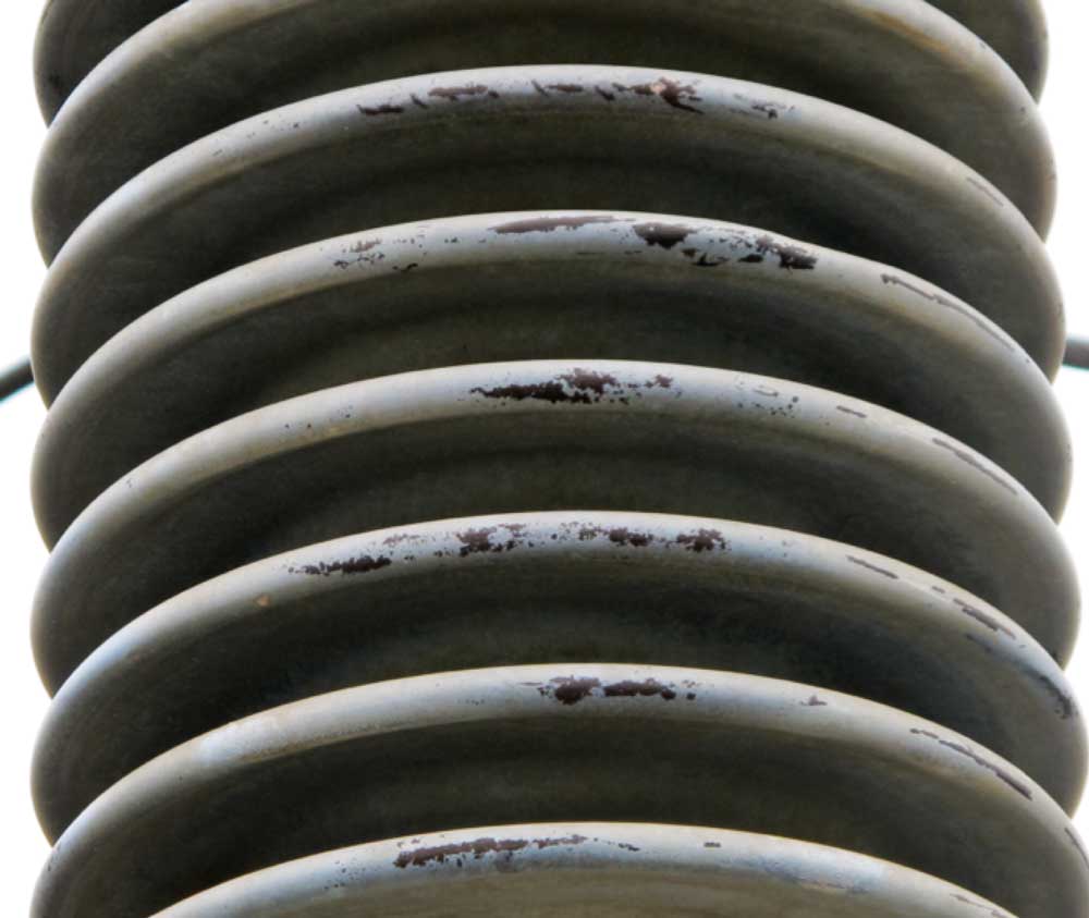
There are certain environments that are optimal for each different insulator technology. Suitably dimensioned insulators of all types will perform well in locations with light to moderate contamination. For contaminated locations that are relatively dry, silicone insulators are advantageous due to their inherent surface hydrophobicity. RTV coated porcelain/glass insulators, by contrast, would be better suited for locations with moderate to high contamination combined with frequent wetting due to mist, rain or fog. In such locations, loss of hydrophobicity from repeated discharges could degrade a silicone housing, thereby exposing a composite insulator to risk of permanent failure.

Still, such a simplistic categorization does not fully resolve the issue since the terms ‘relatively dry’ and ‘frequent wetting’ are qualitative. Contamination levels are generally characterized mainly in terms of ESDD and NSDD. Adding some quantification of relative wetness and/or dryness of a service environment would help in decision-making. One final point. While pre-coating insulators is possible either during construction or after an extended outage, even these insulators will have to be re-coated in the field at least once to ensure a useful service life of 30 or more years. Life cycle costs of each alternative would then also need to be compared to arrive at the best choice.