Over a decade ago, problems of electrolytic corrosion on the caps of ceramic cap & pin insulator strings began appearing on the world’s first ±800 kV HVDC line, located in southern China. Known as Chu-Sui, this line runs across 1200 km of mostly mountainous terrain from the Chuxiong Converter Station in Yunnan Province to Suidong Converter Substation in coastal Guangdong Province. While this corrosion phenomenon was mostly concentrated on V-string insulators on the line’s negative polarity side, corrosion also appeared to varying extents on the positive pole, particularly at the junction between the pin’s zinc sleeve and the cement.
The edited past contribution to INMR by Dr. Mei Hongwei from the Shenzhen Campus of Tsinghua University described the origins of this problem, how it was simulated to evaluate impact on performance and how it was eventually resolved.

HVDC technology has been playing an ever-increasing role in long distance transmission for reasons that include large power transfer capability, low losses, high stability, reduction in required corridors and low short circuit currents.
While silicone composite insulators have played an important role in many suspension applications on Chinese HVDC and UHVDC lines due to superior pollution performance, the mechanical and electrical characteristics of porcelain V-strings have made them the preferred choice for specific sections of line, such as mountainous areas where icing is a concern. However, a problem in these situations has been that the lower side of the V-string insulator can easily be bridged by water during damp or rainy conditions, potentially resulting in electrolytic corrosion on the caps.
Indeed, by October 2011 – not long after commissioning – some 20,000 V-string porcelain insulator discs on the negative polarity side of Chu-Sui already showed evidence of electrolytic corrosion on their iron caps. Moreover, by February 2012, V-string porcelain insulator discs were also discovered to have corrosion problems on the negative polarity side of other HVDC lines, including the ±800 kV Fufeng line and the ±500 kV Tian-Guang, Gao-Zhao and Xing’an lines. Such widespread corrosion of insulator caps was regarded as a serious threat to the safe operation of these important lines and therefore quickly became the topic of research and investigation.

Corrosion of hardware on DC suspension insulators is certainly not new and attracted much attention over the years. For example, I.M. Crabtree in New Zealand offered an explanation of corrosion phenomena in contaminated service environments and during the 1990s performed tests involving different types of steel pins with and without sacrificial zinc sleeves. Moreover, V.I. Galanov reported that the anti-corrosion performance of porcelain long rods was superior to that of disc type insulators without zinc sleeves on the pins. Also, an accelerated ageing test conducted at Xi’an Jiaotong University studied the corrosion mechanism and influencing factors for DC support insulator hardware under polluted conditions. Based on these tests, Wang Xuan reported that electrolytic corrosion of hardware on such insulators could occur in moist, polluted environments and that the extent of corrosion was related to leakage current, specific types of metal and fabrication technology.
Impact of Service Environment
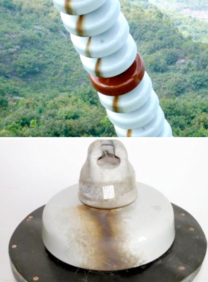
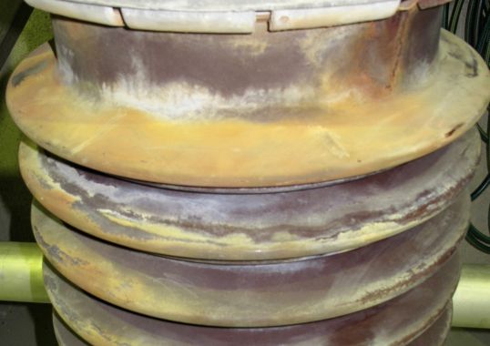
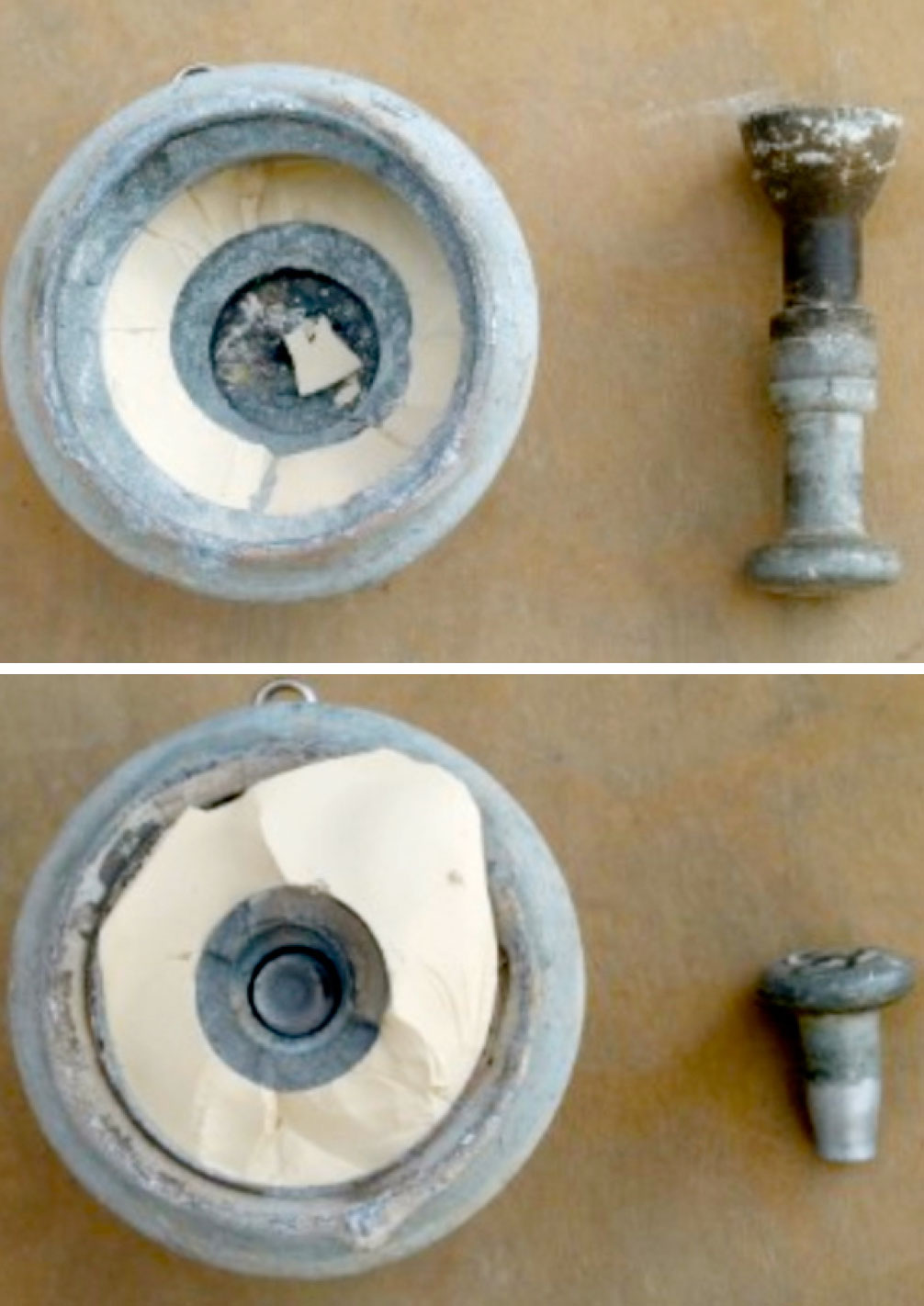
Porcelain V-string insulators that suffered from electrolytic corrosion on the Chu-Sui UHVDC line showed obvious rust channels on their lower surfaces. There was also evidence of similarly induced corrosion of the forged steel pins on insulators installed on the positive pole.
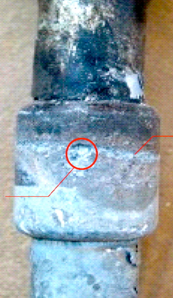
Table 1 provides statistics on the incidence of the corrosion problem in the two line sections mostly seriously affected.
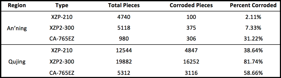
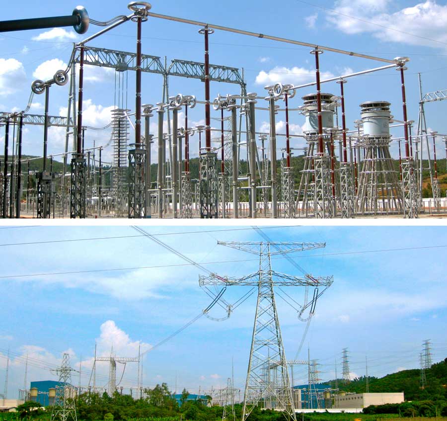
Fig. 2 shows the environment of the line sections with the most serious corrosion problems.

Cause of Corrosion
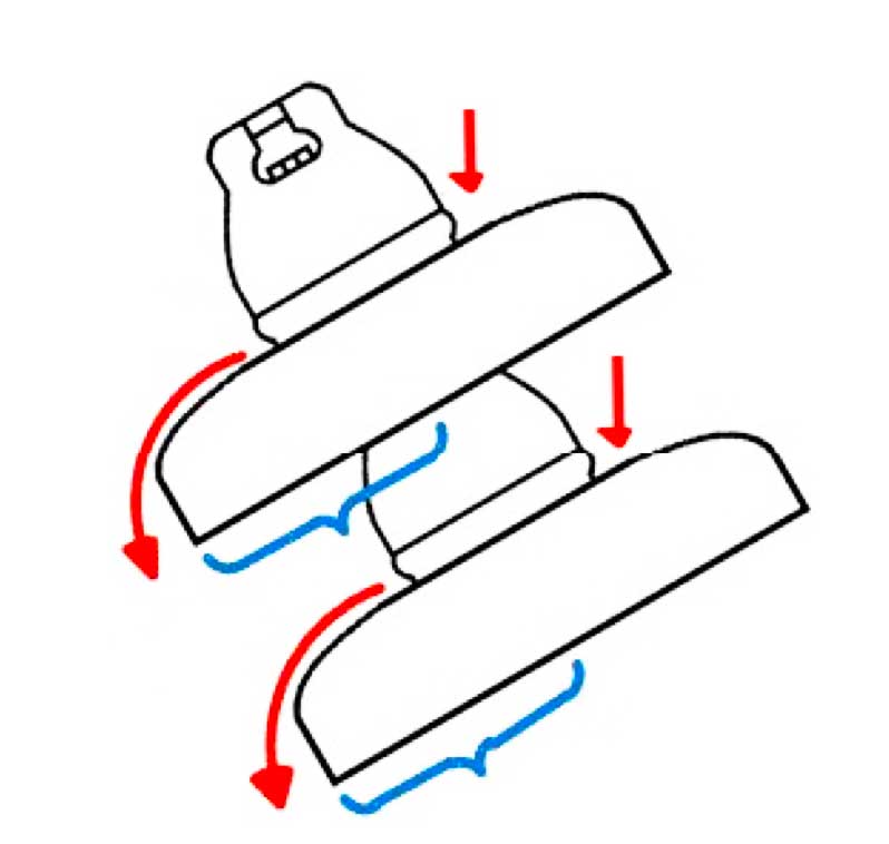
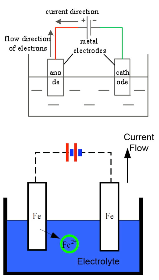
The basic principle behind electrolytic corrosion of hardware on insulators is shown in Fig. 3, with the circuit in this case made up of a DC power supply, metallic electrodes and an electrolyte. The metal connected to the positive pole of the power supply undergoes anodic corrosion by losing electrons. The caps of negative polarity insulators and the steel pins of positive polarity insulators are the cathodes and anodes in this electrolytic loop. Ferrous ions formed by oxidation then transform into rust.
Various tests were conducted of electrical resistance as well as of possible loss of mechanical strength due to the corrosion. Results showed that insulators with corroded caps still satisfied normal operational requirements. However, one obvious concern with rusted portions along the surfaces of porcelain discs was that these might contribute to more rapid accumulation of pollution. To evaluate this risk, three porcelain insulator discs were taken down from tower #407, located in a line section where the corrosion problem was most prominent. These insulators were then divided into three distinct regions (see Fig. 4): Area A which clearly had the by-products of corrosion on their upper surface; Area B, where there was no evidence of corrosion on the upper surface; and Area C, the lower surface.
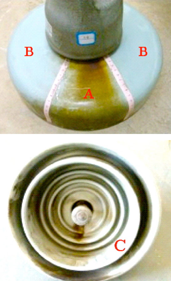
Test results for pollution accumulation in each of these areas are shown in Table 2.
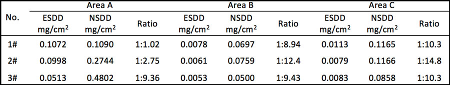
The following observations could be made:
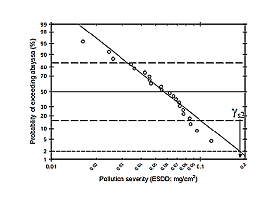
• ESDD levels on Areas B and C of the insulators tested fell between 0.0053 and 0.0113mg/cm2. This suggests that surface pollution level has no impact on the electrolytic corrosion process.
• ESDD and NSDD levels for Area A (with corrosion by-products on the surface) were higher than for Areas B and C.
Another topic of concern was that corrosion of steel pins on affected insulators might decrease their strength, potentially leading to mechanical failure.

Simulation of Electrolytic Corrosion on Insulator Caps
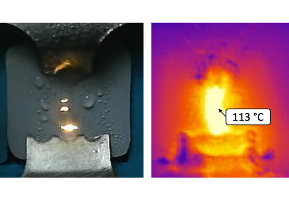
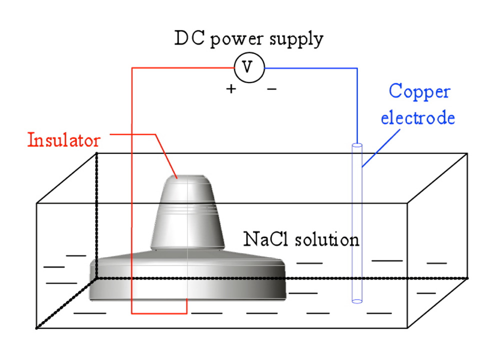
The water spray method was used to simulate the process of electrolytic corrosion on caps of porcelain string insulators. Here, the creepage distance from the lower surface to a portion of the upper surface was deliberately short-circuited using conductive wire and a copper electrode glued to the upper surface (see Fig. 5). In order to prevent this electrode from breaking away during testing, a sealant was used to fix it in place.
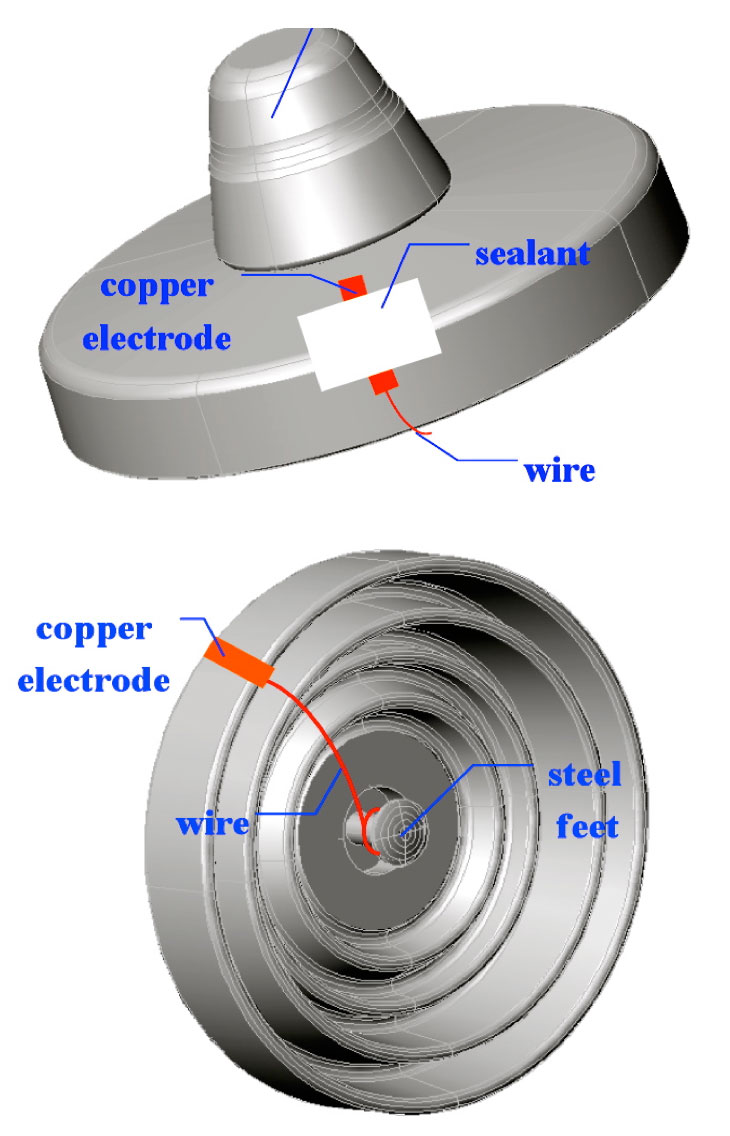
Electrolysis was used to simulate the electrolytic corrosion of the test insulators’ steel pins. To begin with, one end of the conductive wire was wrapped over the pin. Then, the pin and wire were totally covered using a sealant. Finally, the prepared insulator was placed into the electrolytic tank for testing (refer to schematic in Fig. 6).
Since zinc has superior anti-corrosive properties to steel, it has now been decided that new insulators for such lines should be equipped with a zinc ring, which is installed in such a way as to maintain close contact with the iron cap.
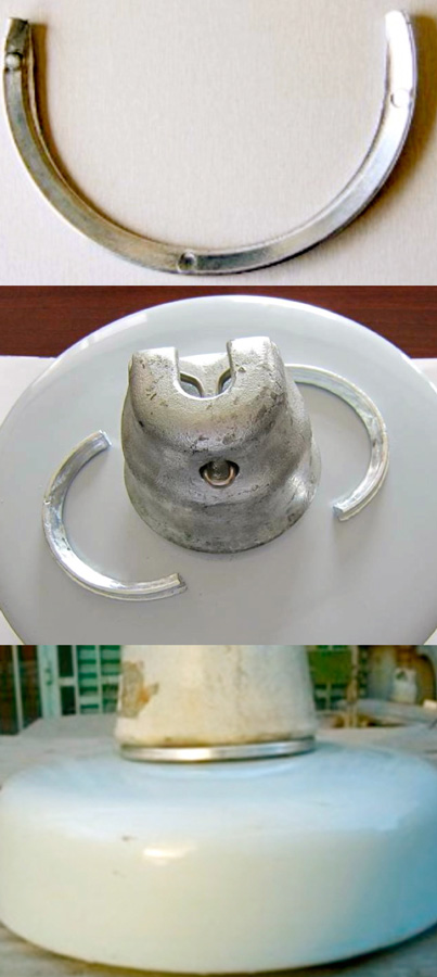
In the case of pins, the remedial measure decided upon involved increasing the required thickness of the protective zinc sleeve and improving sealing.
Conclusions
Several conclusions can be drawn from this service experience and the testing conducted into the issue of electrolytic corrosion of hardware on insulators operating on HVDC and UHVDC lines.
• Insulators with corroded caps and pins still maintained good dielectric performance;
• While degree of pollution on the insulator has no obvious impact on the corrosion process, the resulting channel of rust on the surface makes it more vulnerable to pollution accumulation;
• The water spray and electrolysis methods are feasible to research the electrochemical corrosion problem on insulator caps and steel pins respectively;
• Installing zinc rings is an effective measure to prevent electrolytic corrosion of iron caps. At the same time, increasing the thickness of the zinc sleeve will ensure no corrosion on steel pins.