Capacitive-graded porcelain bushings used in high voltage power transformers and circuit breakers have traditionally been considered one of the weakest elements in Mexico’s power network, with a demonstrated 26% risk of failure. This statistic is based on failures of 230 kV and 400 kV equipment recorded between 1983 and 1998 by the country’s power grid operator, Comisión Federal de Electricidad (CFE).
Polymeric materials have been used in line insulators for over 50 years and are regarded as a mature technology. However, in the case of substation equipment such as arresters, breakers, bushings and column insulators, widespread application of polymeric housings started much later. The advantages of these materials versus porcelain in the case of bushings include lower weight and greater flexibility, hydrophobicity and lower cost for transport and installation.
Bushings and current transformers (CTs) with silicone housings have been installed at 400 kV substations in Mexico going back over 20 years. But in one notable case, failure occurred on one of these bushings only 5 years after installation. This failure focused attention on the need to better evaluate behavior of such equipment, particularly in highly polluted environments.
Preliminary analysis of the incident concluded that special contamination issues, lack of sufficient standards, equipment design being mainly for application in countries with lower average ambient temperatures than in Mexico and deficiencies in installation based on insufficient supplier information all played a role in adversely impacting proper selection of such equipment.
Note: This contribution to INMR by the late Manuel Guzman of LAPEM/CFE dates from 2013. Some comments regarding applicable standards at the time may therefore be outdated.

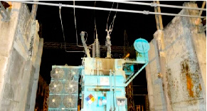
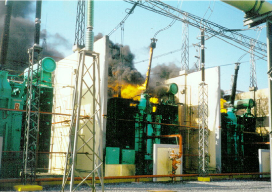
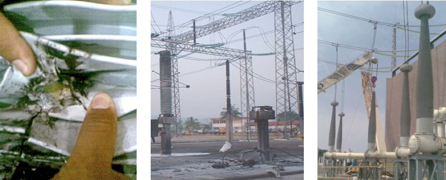
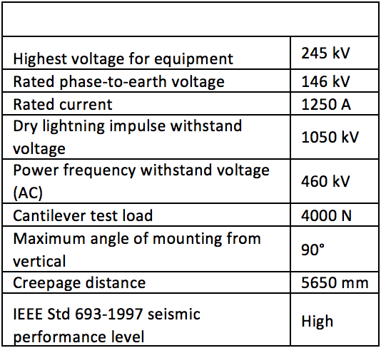
Several failures of porcelain-housed bushings occurred in the wake of two severe earthquakes in Mexico: the first, in October 1995, a 7.9 Richter scale event along the Colima coast and the second, in January 2003, which registered 7.6 on the Richter scale. These areas were the location of two major power plants, Manzanillo I and II, and both suffered severe damage with loss of 1900 MW to the interconnected system for periods of 45 and 30 days respectively. Loss of equipment was due mainly to the vulnerability of porcelain when it comes to withstanding earthquakes. Apart from these seismic events, additional problems in Mexico have been caused by environmental factors – particularly in areas of high pollution, where external flashovers can occur during strong wind. The end-result has been damage to bushings that can sometimes include complete destruction of affected equipment (see Fig 1).
Because of damage to power transformers caused by the first earthquake (i.e. from leaks in 52 of the 230 kV and 400 kV bushings), the two generating plants and substations remained disconnected from the grid for weeks. During the second earthquake, experience gained from the earlier event helped in limiting the damage and resulted in only 2 days of plant downtime. However, the cost of repairing or replacing bushings proved significant and included cost of cranes, materials, manpower as well as lack of availability.
Given this experience, attention was focused on polymeric housings, which can be an attractive alternative to porcelain since they make the bushing lighter and facilitate both transport and installation. These types of bushings also offer other advantages, including surface hydrophobicity that assures good performance under polluted conditions. Their lower weight, easier handling and higher mechanical stability together make them an ideal solution for application in seismic areas where the silicone external insulation also assures that there is no hazard due to explosion, no damage to adjacent equipment in the event of failure and greater resistance to bending motion. For example, the greater flexibility of polymers compared with inorganic porcelain means that the silicone rubber housing withstands up to 10 times more tensile stress without failure. This suggests that polymeric bushings can better withstand earthquakes of more than 1.0 g. Finally, the same polymeric material with high flexibility helps seal in insulating fluids, preventing oil leaks if displacements take place. There is continuity of service even with damage to some sheds.
Damage to porcelain skirts from bullets or other projectiles, such as stones, is common in rural areas of Mexico. While in the case of porcelain housings any fracture causes leaks and consequent failure of the equipment, this type of failure mode is much less likely for silicone rubber housings, representing an important advantage for HV equipment operation.
Resistance to Environmental Pollution
One of the factors when evaluating a polymeric material to ensure proper performance as a housing for HV equipment is resistance to environmental pollution. Such pollution can be semi-conductive or insulating but, when wetted by rain or other moisture, the bushing’s field distribution and capacitive grading can change. When contamination becomes deposited onto the sheds (skirts) of a bushing, electrical field becomes concentrated in wetted areas. Leakage current then causes the moisture to evaporate, resulting in appearance of dry bands. In areas with dry band arcing, localized ionization causes heating, tracking and erosion. A hydrophobic surface avoids the presence of dry bands and wetted areas. In the case of a silicone rubber housing, it has been found that hydrophobicity is maintained even over long periods in operation and, if temporarily lost, requires only about 8 hours without dry band arcing to restore its initial hydrophobicity. Another important point is that even if the surface is contaminated and the pollution layer not too thick, the polymeric surface remains hydrophobic.
Service Experience
A. Manzanillo
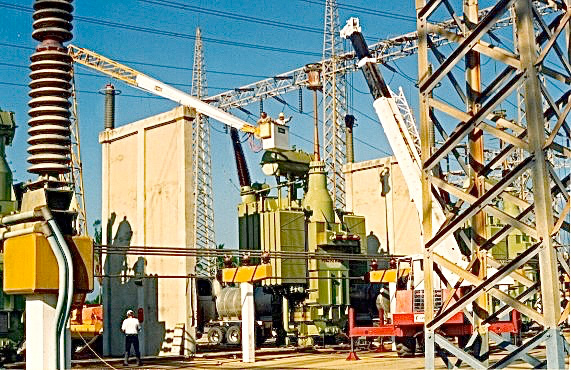
The first CFE project with these types of bushings was in the Western Transmission Area, specifically the Manzanillo Substation, where, a total of 10 power transformers had their porcelain bushings replaced (Fig. 3).
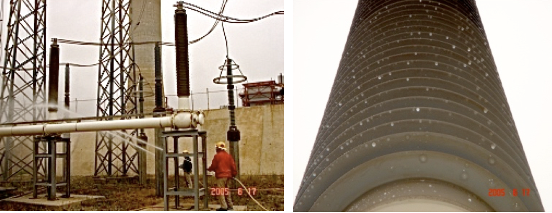
New silicone rubber bushings using resin-impregnated paper (RIP) technology replaced oil-impregnated paper bushings (OIP) with ceramic insulation. The objective was to reduce the risk of damage due to earthquakes and pollution. Another potential benefit was reducing the need for hot line washing. With the previous porcelain bushings, washing was done during 7 months of the year whereas this was reduced to only once per year or less for the new silicone-housed units. At the same time, the 400 kV conventional air-insulated substation was replaced by a gas insulated substation that used 21 silicone rubber bushings to interconnect with transmission lines, making this the largest installation of these types of bushings in Mexico.
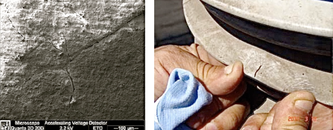
However, failures have since occurred. In one case, the silicone sheds of a bushing were damaged due to mechanical impact of debris thrown out from an exploding nearby porcelain-housed instrument transformer. Fig. 4 shows a close-up of one damaged section where it can be seen that the impact of debris caused a cut in the rubber to extend all the way to the resin core. Since this would eventually allow moisture to penetrate into the core and cause failure, this equipment was immediately replaced. This experience caused a modification in the criteria to install non-ceramic bushings and it is now recommended that installation not be too close to porcelain-housed equipment in order to increase bushing reliability.
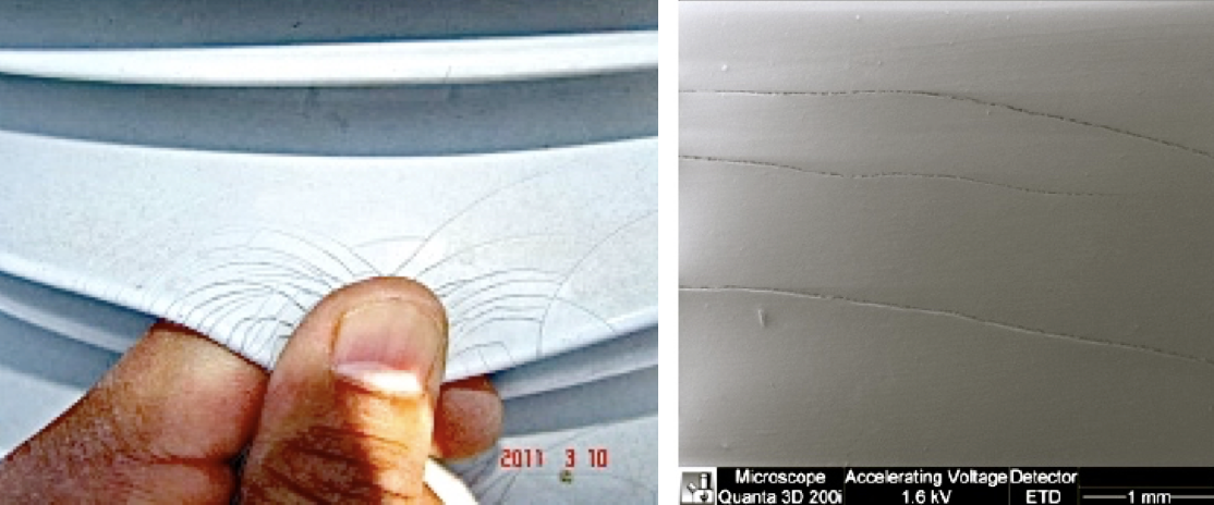
In another case, one of the silicone bushings developed ‘alligatoring’ on the surface after operating from 4 to 5 years in an area of heavy contamination. Some of these bushings, installed on the primary and secondary side of power transformers, had lost most of their hydrophobicity (HC of 6) after only 5 years in service. Figs. 5 and 6 show two different bushing surfaces with moderate degradation after 5 and 4 years of service and HC 3 and 4 respectively on the upper surfaces of sheds. On lower surfaces, hydrophobicity was HC 1 but there was evidence of light cracking. Based on the performance of these bushings, it has been deemed necessary to conduct detailed examination of them every year to assure their safe operation.
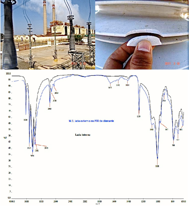
In another case, a 400 kV air to GIS bushing (Fig. 7) showed a HC 6 on the upper side of sheds. The bushing shed material had become rigid, brittle and easily torn, with deep cracks and loss of insulating material. An IR spectrum of this silicone material revealed critical degradation compared with a typical polydimethylsiloxane (PDMS) spectrum and the manufacturer was asked to replace the bushing.

B. Salamanca
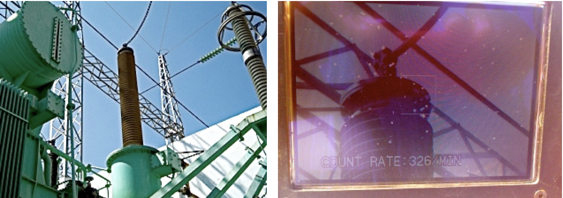
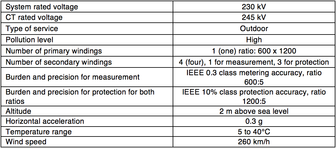
A silicone rubber RIP bushing was installed in 2006 near a 946 MW power plant in an area of central Mexico with heavy industrial pollution (Fig. 8). The characteristics of this bushing are shown in Table 1. After 7 years of service, with annual cleaning using a cloth, visual inspection revealed no surface degradation, even though it had been contaminated with combustion deposits. Performance under wet conditions was good and corona inspection showed no evidence of damage to the insulation along the bushing. There was only limited corona activity observed around the high voltage conductor (see Fig. 9), attributed to high electric field strength in that region.
C. Mazatlan
Silicone housings were also applied to an instrument transformer installed in Mazatlan. The silicone-housed current transformer, shown in Fig. 10, was ordered with specifications based on the electrical system requirements and it main characteristics are listed in Table 2. During installation, one of the main cautions was to exercise care when installing the current transformer column because damage could occur if pressure was applied over the sensor during erection. Another precaution was to avoid anything striking the column to ensure no nitrogen would leak from its interior. Installation proved easier compared to a porcelain-housed unit due to the much lower weight. This was seen as an opportunity for additional installations of silicone housed CTs because of the lower amount of civil work and structural requirements needed. In this case, the silicone rubber CT was installed over a metallic post, with connection box at the column’s base.
Connections of the fiber optic cable, modulator cable and temperature sensor were done in the connection box at the base of the column. The silicone-housed CT required two connections to the control center – one at the base of the column and the other in the control room. One of the connections was repeated due to problems in the optical transmission. After completion of the connections, the system was energized and it was realized that a stabilization period of 20 minutes is necessary for the silicone CT to reach full precision. Measurements from the silicone-housed CT were compared to a conventional bushing type CT using an OPH instrument and the difference in measurements was less than 3%.

D. South
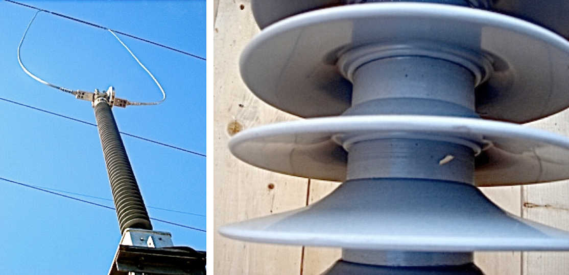
Solid core, one piece HTV silicone insulators were installed as bus supports near a 252 MW combined cycle power plant in the southern part of Mexico where both temperature and humidity are high. The insulators (Fig. 11) required no maintenance and are still in good conditions after 10 years of service.
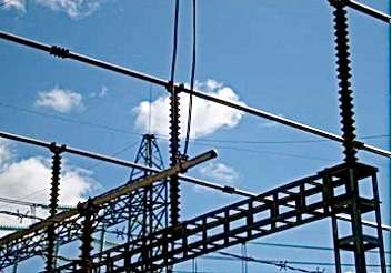
Fig. 12 shows a 115 kV bushing after 10 years in operation at the Nizuc GIS substation. This location is near the Caribbean coast and service conditions include high humidity and sea contamination.
E. Baja California
A polymeric bushing with 12 years in operation near the Pacific coast required washing at least once a year. It was installed as part of 230 kV GIS located beside a 496 MW power plant (see Fig. 13). The polymeric insulation is still performing well in the local harsh environment and there have been no reports of failure.

Discussion
During the early 1980s, both silicone rubber and EPDM were commonly used for line insulators but field experience soon showed that silicone was the better option. HTV silicone rubber has since become the most popular type of material for this application. In order to improve manufacturing processes for hollow core composite insulators, a number of different techniques have been developed, including helical extrusion with HTV silicone as well as casting and injection with liquid silicone rubber (LSR). Some of the latest LSR 1:1 formulations require up to 70°C for vulcanization, however silicone is but one component of the system and therefore typically has to meet equipment characteristics instead of defining them. Often, the best silicone formulations may not be feasible for manufacturing due to equipment limitations. In addition, any change in silicone materials can require major process modifications, including in the equipment itself and also new design and type tests for the modified component.
As is the case for insulators as a proportion of the total investment to build a new line, the cost of a bushing is relatively low compared to the value of the equipment where it is installed, i.e. usually from 5 to 10 percent. But its performance can affect the safe operation of that equipment or substation and thereby affect many customers. A decision to try even a relatively mature technology may therefore be different in a small power company versus a utility with more than 3000 substations from 69 kV to 400 kV.
In Mexico, the CFE was motivated to begin use of polymeric-housed bushings by factors such as easier handling, better pollution performance and outstanding seismic performance. Another reason was reduced safety risk, both for personnel and other apparatus located near arresters and other equipment capable of explosive failure from high internal pressure. However, experience with premature failure of certain of these units has made the utility concerned that application of polymeric insulation technology to bushings may have been made without sufficient study of their behavior outdoors under high pollution and intense radiation and based mainly on service experience with silicone line insulators.
Introduction of this technology into the market has come with several serious failures that risk jeopardizing its continued use. For example, premature failure of polymeric bushings at a GIS substation began the process of imposing restriction on these materials in the Mexican transmission system and delayed realization of all the benefits that this advanced technology can offer. Based on failure analysis, the materials involved were identified as silicone rubber with a minimum PDMS content of 30% by weight. It is interesting to note that much the same process of delayed introduction occurred with transmission line insulators in the 1980s due to several highly publicized brittle fracture failures.

Even in the activities of IEC WG D1.27, it is not easy to identify the composition of a polymeric material and it is difficult for utilities to identify the process and validate the equipment against previous testing. The standards for HV equipment normally refer to the polymeric insulation standards so as to fulfill the technical requirements. For example, IEC 62231-2006, which applies to composite post insulators for substations with AC voltages, refers to IEC 62217 for several electrical tests, e.g. on interfaces and end fitting connections. IEC 62231 indicates that pollution tests should be as specified in IEC 60507 but the standard mentions that such pollution tests, performed on composite insulators, do not correlate with experience obtained from service. Moreover, these pollution tests are still under consideration. On the other hand, IEC 60137-2008, applicable for insulated bushings and including composite bushings, indicates that if artificial pollution tests are required, they shall be performed according to IEC 60507, which is the standard for ceramic and glass insulators exposed to polluted environments.
The former IEC 1109, considered a set of tests including design test and type test. Now, an updated document published in 2008 established the 1000-h a.c. tracking and erosion test of IEC 62217 as a minimum requirement for the tracking resistance of a housing material. The new version of IEC 61109 changes the concept of tracking and erosion test and includes the tracking wheel test to ‘screen’ designs. The standard would be acceptable for overhead lines insulators. The recent IEC 62217-2012, Polymeric HV insulators for indoor and outdoor use, considers the 1000 hour salt-fog tracking and erosion test as a screening test intended to reject materials or inadequate designs. Of course, this is a minimum requirement for polymeric insulators used outdoors or indoors, and includes solid core as well as hollow core insulators. From this standard two alternative tracking and erosion tests were removed – the 5000-h multi-stress test and the tracking wheel test now both included in IEC/TR 62730-2012 with the same screening criteria.
IEC 60815-3, published in 2008, considers a Unified Specific Creepage Distance (USCD) varying from 22 mm/kV to 53.7 mm/kV depending on the site pollution severity (SPS) class. The USCD is the same for ceramic and glass insulators for a.c. systems according to IEC 60815-2. Moreover, IEC 60815-3 includes recommendations for polymeric profiles, correction factors for altitude and insulator diameter as well. The most important point is that the standard considers three operating areas as a function of pollution severity and USCD (for a fixed insulating length). In Area 1, creepage distance is too low, which will result in increased flashover probability. Within Area 2, design and creepage distance are correct, which will result in minimal probability of flashover and damage. Finally, in Area 3, the creepage distance appears correct but is obtained by incorrect design, which will result in increased risk of damage. However, the relationship between size and position of the areas and safe operating regions (SOR) and the values of the diagram axes depends on pollution, climate and the properties of the housing material and design; hence, a general recommendation is not given in IEC 60815-3. For the last point, the standard recommends outdoor testing for at least one year, monitoring leakage current, flashovers and degradation to housing and interfaces. Tracking and erosion tests are considered in IEC 60587 for insulating materials and, based on experience with high voltage insulators, the recommended minimum requirement is 1A3.5 according to IEC/TR 62039-2007, which means 3.5 kV. However, in very polluted areas, as found in Mexico, this value is now questionable since equipment with insulating materials that presumably passed the 4.5 kV level failed due to pollution.
Before 2007, CIGRE WG D1.27 dealt with properties and methods to evaluate polymeric materials, specifically the ‘fingerprint’, and dealt with loss of hydrophobicity and ageing. The main methods identified included:
• Differential scanning calorimetry (DSC) to measure the endothermic or endothermic properties of the material;
• Thermal gravimetric analysis (TGA) to measure the thermal stability of the silicone rubber. As temperature increases, weight loss occurs due to release of moisture or gases from the decomposition of the silicone rubber. In the end, only a non-volatile residue remains;
• FTIR to analyze the absorption of infrared radiation due to vibrational motions in the molecules. Characteristic vibrational frequencies in spectra provide distinct identification of the silicone rubber molecules;
• Gravimetric analysis for determination of filler content.
Actual bushing standards do not consider additional tests, as considered in IEC 62217 for hollow core insulators and IEC 61109 for overhead transmission lines. Also, standards for HV equipment consider a correct procedure to compute the contamination behavior for a new polymeric design, but without specific experimental support to confirm it.

Conclusions
Cost has become a main driver and it would be a good decision to agree to standardization in both materials and manufacturing. Also, additional tests, e.g. Fourier transform infrared spectroscopy (FTIR), X-ray diffraction (XRD), IR thermography, computer tomography and shearography should all be used during acceptance tests to identify the presence of any voids, cracks, de-laminations or poorly bonded areas and should also be considered in the standards. Customers typically do not have information about possible changes in materials and manufacturing or the tests performed to validate these. Customers and manufacturers need to focus experience and new technical developments to write new standards that better discriminate good from bad formulations and designs.
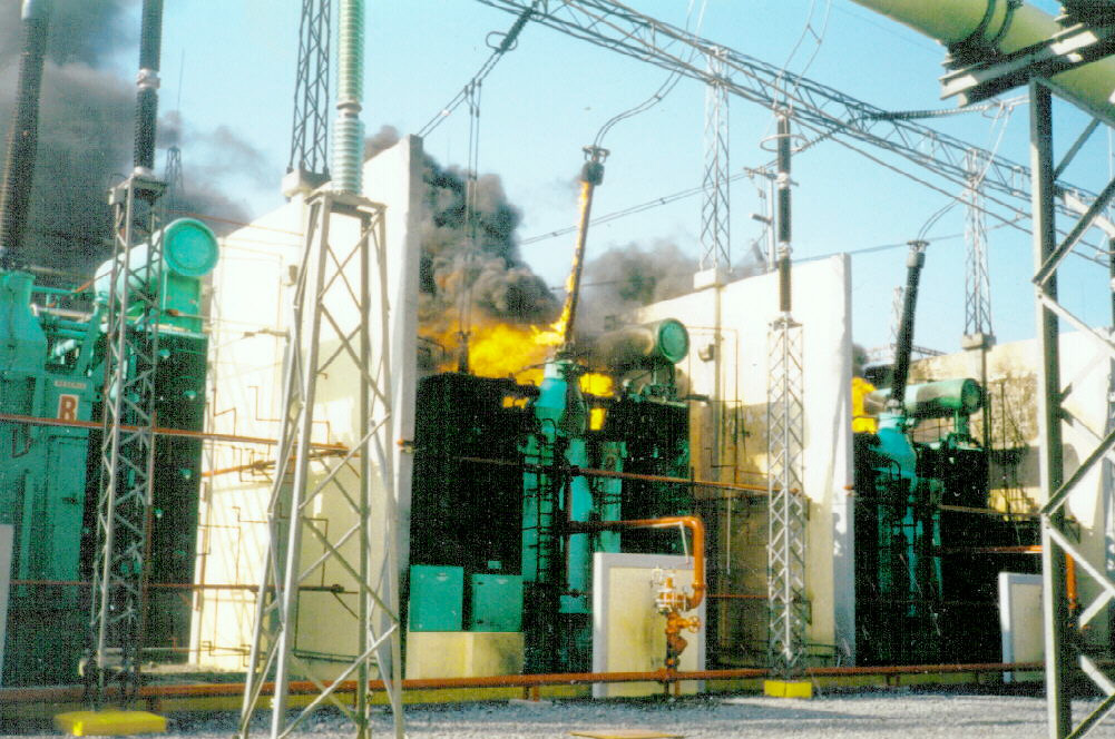
Polymeric-housed bushings offer the promise of much better flashover performance but their failure can lead to heavy damage to substation equipment and great cost to replace it (see Fig. 14). Due to this specific failure, as well as those highlighted in Figs. 5 and 6, the CFE decided to develop its own national standard for HV equipment with silicone rubber housings. The main point in this standard has been to require several tests not included in the international standards such as: inclined plane tests with a test voltage of at least 6 kV; adhesion tests for the housing; FTIR; TGA; and a tracking wheel test as an alternative to the 1000-h salt fog test.