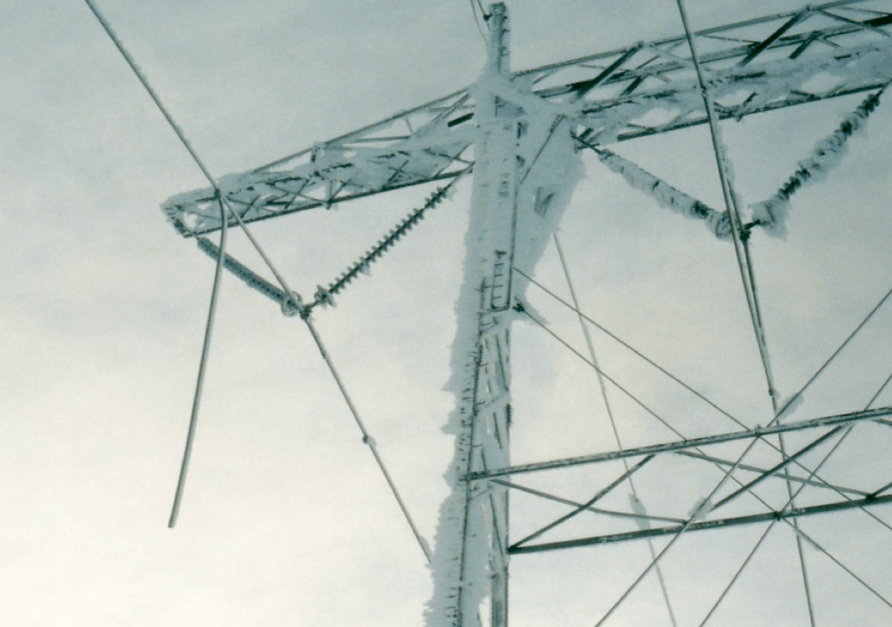
In many parts of the world, ice and snow accretion on network equipment such as conductors, ground wires and insulators are a great concern for power system operators. The disruptive effects of icing result from excessive ice or snow accumulation, combined with wind forces, as well as subsequent jumping of cables and conductors following sudden ice shedding. Other potential sources of failure include dynamic phenomena such as galloping often involving extensive dynamic forces.
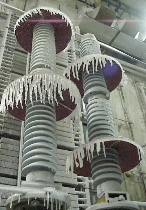
Electrical flashover along iced or snow-covered insulators is another major problem affecting reliability of overhead lines and outdoor substations. The catastrophic socio-economic impact of some major icing events such as those that struck regions of North America and China in 1998 and 2008 respectively sparked substantial R&D collaborative projects between academia and industry. This concerted action led to much innovation and improvement of overhead network design, construction and operation.
However, despite the progress, the knowledge base when it comes to this complex and unpredictable phenomenon is still not sufficient – all the more so when considering increased extreme meteorological events likely caused by climate change. Furthermore, continuous increase in energy consumption and the need for upgrading existing networks, and constructing more reliable transmission lines, call for innovative solutions to icing issues.
This edited past contribution to INMR by Prof. Masoud Farzaneh (retired from the Université du Québec à Chicoutimi in Canada), dealt with the impact of icing on conductors, ground wires and outdoor insulators as well as mitigation options to improve reliability under such conditions.

Atmospheric Icing Processes
Atmospheric icing (or simply icing) refers to freezing and sticking of water in various forms on the surface of an exposed object. Therefore, icing describes both ice and snow growth on exposed structures such as power network equipment.
 Icing can be classified into different categories:
1. Precipitation icing, such as freezing rain and snow;
2. In-cloud icing, involving freezing of supercooled water droplets in a cloud or fog upon impact with an exposed structure;
3. Hoar frost, resulting from condensation of water vapor in air on a structure when temperature is below 0°C.
Types of Accretion
Depending on atmospheric and metrological parameters (air temperature, wind speed, precipitation rate, relative humidity, liquid water content, etc.) various types of accretion can occur on overhead lines and outdoor substations. These are classified as:
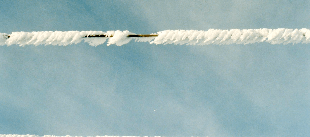
• Glaze ice with density of 900-920 kg/m3 has clear structure without air bubbles and generally forms with icicles. Glaze ice accretion on an exposed structure is typically the result of accretions from freezing rain or drizzle. It may also result from in-cloud icing when influx of cloud water is high.
• Rime ice has density ranging from 150 to 700 kg/m3 and occurs at temperatures below –5°C when impinging small supercool water droplets freeze spontaneously on an exposed structure. This type of accretion is typically formed on structures in hilly areas over the cloud base or on structures exposed to cold fog. Depending in its physical appearance, structure and density, rime ice is classified as hard rime or soft rime. Hard rime is characterized by a homogenous opaque structure and density varying from 300 to 700 kg/m3 and is grown homogeneously with air bubble inclusions. Soft rime has a granular opaque structure and a density ranging from 150 to 300 kg/m3. It grows in a granular structure with many air bubbles.
• Wet snow occurs at air temperatures above the freezing point, usually between 0.5 and 2ºC. Depending on liquid water content and localized wind speed, density of wet snow varies from 100 to 850 kg/m3.
• Dry snow with density not exceeding 100 kg/m3 occurs at sub-freezing temperatures and can accumulate on exposed structures under low wind speed conditions.
• Hoar frost has density of less than 100 kg/m3 and is deposited as interlocking ice crystals formed by direct sublimation of freezing water vapor in air on an exposed structure.
Due to variations in meteorological conditions, atmospheric ice accretion can be a mixture of two or more different types of icing. Among these, glaze, hard rime and wet snow with relatively high water content have strong adhesive force when accumulating on exposed structures. As for dry snow, soft rime and hoar frost, adhesion strength is normally low such that these accretions are easily blown off by wind or shaken off from conductors or earth wires. In the case of hoar frost, while the increase in ice load is usually small, it can nevertheless cause high corona losses on HV and UHV lines.
Impact of Ice & Snow Accretion
Mechanical Issues
![]()
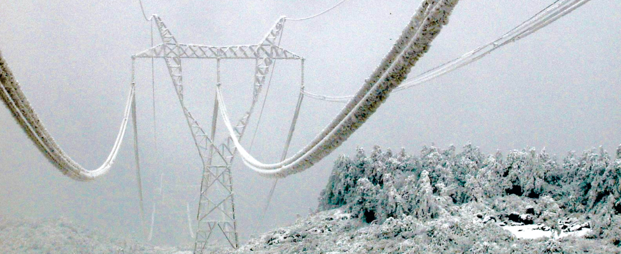
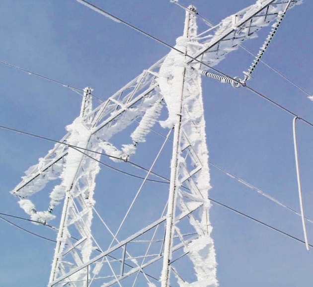
Icing or combined loads of wind and icing can severely impact overhead transmission and distribution networks in regions with cold climates. For example, overloading of conductors and ground wires by heavy icing, sometimes combined with wind forces, can cause them to break sometimes leading to tower collapse. In addition to excessive loading, other phenomena such as conductor and ground wire galloping, ice or snow shedding from conductors and ground wires as well as rolling of bundled conductors can induce severe loading issues, as detailed below.
Galloping of Conductors & Ground Wires
Galloping, a wind-induced instability, occurs under moderate and strong wind on ice or snow-covered conductors and ground wires. This perturbing phenomenon, with peak-to-peak amplitude reaching up to 15 m, can result in phase-to-phase flashover or in direct contact of phase conductors resulting in short-circuits and outages. This dynamic phenomenon can also result in fatigue problems as well as serious mechanical damage to conductors, hardware and support structures.
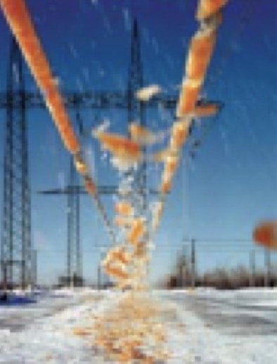
Ice & Snow Shedding from Conductors & Ground Wires
Ice or snow shedding from conductors and ground wires can induce dynamic forces similar to those from conductor galloping. The rate of ice or snow shedding at the source of these dynamic transient forces is affected by ice or snow morphology, meteorological conditions, wire and conductor characteristics and temperature, as well as structural design of lines. Sudden ice or snow shedding from conductors could cause high dynamic forces and consequently rebounding of conductors and their high amplitude vibration. This can lead to the reduction of clearance between the affected conductor with an adjacent phase, ground wires or part of tower causing electrical flashovers. The excessive induced dynamic forces could also cause failure of the tower arms and even cascade failure of several adjacent towers. Ice shedding over roads and highway also endangers public safety.
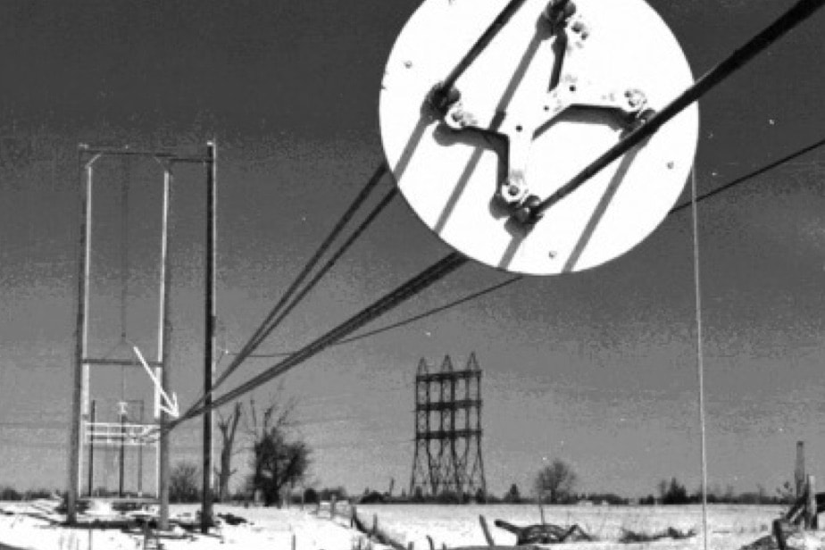
Rolling of Bundle Conductors
This phenomenon is observed in mountainous areas subjected to excessive rime ice accretions on transmission line bundle conductors. It can also occur under glaze ice on long spans over valleys or rivers and the instability can cause damage to spacers and conductors resulting in power outages. Fig. 1 illustrates physical modeling of this phenomenon. Tests were carried out with two- and four-conductor bundles using two span lengths, several arrangements of spacers and six different types of spacers.

Electrical Issues
In addition to the above phenomena that are the origin of mechanical damage and failure of power equipment and support structures, ice and snow accretion on high voltage equipment are sources of other types of perturbations resulting from interaction between electric field, liquid water, ice crystals and surrounding air. Possible electrical issues from icing include the following:
• Partial discharges and local arcs;
• Corona noise and power loss;
• Electromagnetic interference;
• Flashovers of insulators.
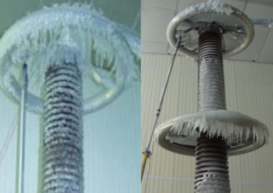
Among the above-mentioned electrical phenomena, flashover of ice- and snow-covered insulators have attracted attention by researchers as well as power utilities since these can be a source of failures and outages. Indeed, insulator flashover problems under icing conditions have been reported from various countries experiencing atmospheric icing. According to these reports, the number of such incidents increases during icing precipitation or after accretion followed by a rise in air temperature above 0ᵒC. For example, a 2006 CIGRE survey reported that icing flashover problems occurred on 400 kV to 735 kV networks at 35 utilities in 18 countries and involved station as well as line insulators, whether clean or pre-contaminated. Flashover problems on 115 to 230 kV networks have also been reported under combined ice and pollution conditions. Icing flashover is of particular concern for insulators in service close to high-traffic areas where road salt or other types of anti-icing fluids are used. These conditions can cause rapid build-up of contamination on exposed insulators from salt spray. This is also the case for insulators installed near by cooling towers.
Mitigation Option Related to Conductor & Ground Wire Icing
Different strategies have been used by line designers and utilities to prevent or limit extended power outages caused by mechanical icing issues. These include a range of different measures. In general, the designers of overhead power networks do what is necessary for an appropriate design of lines and structures to withstand the effects of ice and snow accretions, taking into account wind forces, based on the prescription of available standards and information provided in technical guides. When possible, areas prone to high icing loads are avoided during the design process. However, prevention of mechanical damage and failures caused by extreme ice and snow loading would require the construction of lines with larger diameter conductors and wires as well as stronger towers. This generally would involve major investments that are not profitable and realistic. On the other hand, an appropriate design of the lines, even with reinforced elements, cannot always resolved all the icing problems. Hence the necessity of monitoring ice and snow accretion and integrating techniques to prevent ice and snow adhesion and accretion, or their removal, before exceeding a critical ice or snow thickness. These techniques are classified as follows:
1. Anti-Icing (AI)
2. De-Icing (DI)
3. Use of passive devices
4. Line design approach

Anti-Icing Techniques
These techniques are used to prevent or reduce atmospheric ice (glaze ice, snow, rime or frost) from accumulating, based on ice adhesion strength reduction or freezing of supercool droplets.
Use of Passive Coatings
A number of physico-chemical properties of icing surface, including surface energy and surface roughness, influence the adhesion force between atmospheric ice and substrate. One of the methods to reduce ice adhesion is based on so-called passive coatings that require no external energy to be effective.
Viscous Coatings
Ice adhesion on an exposed surface can be reduced by applying a viscous or liquid coating such as industrial lubricants, oils and grease. These lead to ice release by gravitational, vibration or wind forces. Indeed, laboratory investigations have demonstrated that lithium grease and industrial lubricants can reduce ice adhesion strength on an aluminium surface by a factor of as much as 63. However, this type of protection is temporary and would require re-application as well as accurate field observation to predict the next ice storm. Finally, since these products are not biodegradable, they constitute an environmental threat. For these reasons, such coatings are not considered suitable for broad use but can still represent a last resort to protect strategic line sections when severe icing storms are being forecast.
Freezing Point Depressant Fluids
This technique makes it possible to avoid ice adhesion and formation on an exposed object. These fluids are generally prepared by mixing commercial liquid products with water and are commonly used on roads, runways, aircraft and other structures to prevent icing. Durability of these coatings on aircraft wings, for example, is limited to about one hour. As such, application of such fluids to power equipment does not seem practical considering limited durability, cost effectiveness and harm to the environment.
Solid Coatings
This approach consists of decreasing ice adhesion by elaborating ice-phobic coatings from materials of low surface energy, such as Teflon or silicone-based polymers, or by using heterogeneous polymer coatings. However, from a practical viewpoint and in spite of their ability to reduce ice adhesion strength, these materials cannot be considered as ice-phobic, considering that accreted ice on cables and wires will not detach under its own weight or from the action of the wind. Recent development in research concerning surface wetting and ice adhesion as well as new advances in material and surface science have resulted in development of advanced super-hydrophobic coatings with self-cleaning and ice-phobic properties. These coatings, featuring nano/micro surface roughness, can prevent or considerably reduce ice adhesion strength on surfaces by breaking the chemical bonding involved in ice adhesion and/or by intercalating air between the solid surface and the ice.
Application of these coatings to conductors, ground wires and supporting structures can potentially reduce mechanical loads due to ice and snow accretion thus increasing reliability of transmission during winter conditions. A comprehensive review of these coatings was carried out by CIGRE WG B2.44 and resulted in publication of Technical Brochure 630 in 2015. An update of this study is currently in progress within the framework of CIGRE WG B2.61. Despite investigations in many countries and progress in development of ice-phobic coatings, there are still limitations in regard to application to overhead conductors and ground wires. This is due mainly to the stability and durability of coatings developed so far. Conductors or wires coated by a black or an efficient heat absorbent can create favourable conditions to capture energy from the sun and atmospheric light to accelerate ice and snow shedding. This technology, now used on solar panels installed in cold climate regions, would be of potential for application to conductors and especially to ground wires.
Use of Active Coatings & Devices
In contrast to passive coatings, active coatings need external energy to be effective. In the same way as passive coatings, active ones can prevent or reduce ice-adhesion strength on surfaces by breaking the chemical bonding involved in ice adhesion and/or by intercalating air or other gases between the solid surface and the ice. Other such coatings work by weakening ice-adhesion strength by generating heat or an interfacial mechanical stress between ice and substrate in order to produce adhesion failure of the ice layer.

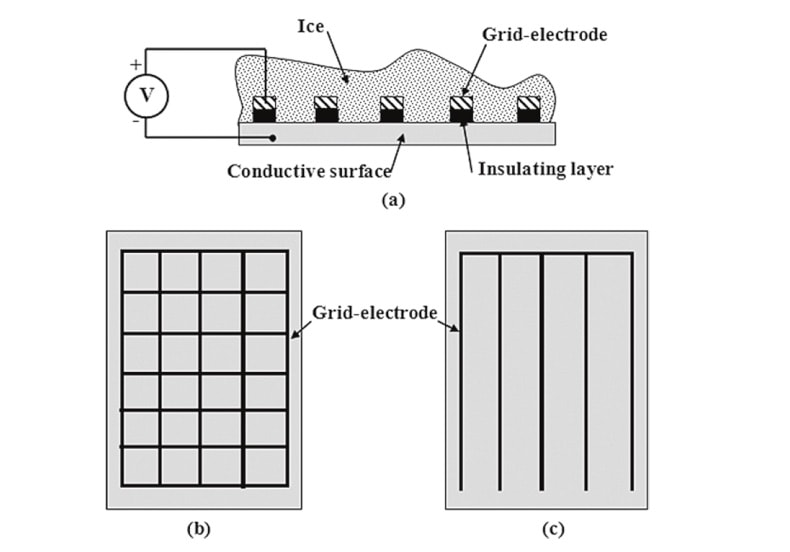
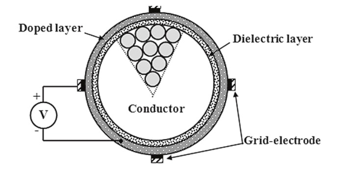
Ice Electrolysis System
One of these methods is based on ice electrolysis and consists of applying a DC voltage between a grid-electrode and a conductive surface to be protected when ice forms on the surface and bridges the circuit (see Fig. 2). The grid-electrode is insulated from the conductive surface (Fig. 2 a) and can have different configurations, as shown in Figs. 2b and 2c. The ice electrolysis gases produced by this system are intercalated between the ice and the solid surface. Gas also accumulates in the form of bubbles that contribute to produce interfacial cracks.
Voltage, US Patent 6027075, reproduced and published in ref. [10] by permission of Victor F. Petrenko
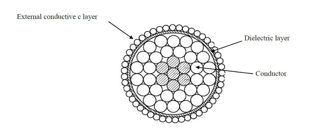
This method relies on the injection of a pulsed current into a conductive coating surrounding the conductor for heat generation at the interface of ice and an external conductive layer. As shown in Fig. 4, the external coating is isolated from the body of the main conductor by a dielectric layer. Compared to de-icers using alternating or direct current, this de-icer requires an average power approximately 100 times lower. Problems such as the need for significant changes in conductors and its thermal limitation caused by the addition of the dielectric layer, limit the use of this concept.
LC-Spiral Rods
Another such a technique, reported in CIGRE Technical brochures, is based on use of a ferromagnetic coating (see Fig. 5). The principle of such a system consists of absorbing energy by a Low-Curry (LC) Spiral Rod from the alternating magnetic field produced by conductor current. The heat energy necessary for snow melting is generated by hysteresis and induced eddy current.
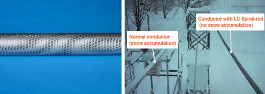
LC-Spiral Rod has been implemented in Japan about three decades ago to prevent accidents caused by sudden fall of large chunks of snow. One of the advantages of this de-icing device is its capacity to generate a relatively large amount of heating energy during winter and a small amount in summer. The heating generated can be adjusted by winding tightness using a wrapping machine. Based on experiments at a Hydro-Québec natural site, this technology, efficient for wet snow melting also seems effective under icing conditions with favourable weather and current conditions.
Active Materials
Another potential active coating for application to conductors or ground wire is based on active materials such as piezoelectric films and electro-active polymers. Piezoelectric polymers such as PVDF seem appropriate for this purpose since they are thin, flexible and can support high mechanical and electrical stresses. Electro-active polymers, and particularly dielectric elastomers consisting of a polymer material sandwiched between two compliant electrodes, can also provide thin-film active coatings. Applying a high electric field to the electrodes makes it possible to stretch the polymer under Maxwell stress. The mechanical stress generated, i.e. up to 7 MPa at the ice/substrate interface, seems sufficient to de-bond the ice layer. Further research is necessary to verify the efficiency and applicability of PVD and electro-active polymers to overhead conductors and wires.
De-Icing Techniques
De-icing techniques are used to remove ice accretion on conductors or ground wires during or following an icing event. Generally, both thermal and mechanical approaches are used: Thermal techniques are based on heating conductors or ground wires to melt ice deposits so as to force its shedding; Mechanical techniques, by contrast, are based on ice breakage in order to force ice shedding. A comprehensive review of these techniques was carried out in several publications and a review of de-icing and anti-icing techniques was also recently presented recently in IWAIS 2019. Following is an overview of such de-icing techniques:
Thermal De-Icing Techniques
These techniques, using the Joule effect for de-icing conductors and ground wires have been developed and used widely for about a century using both AC and DC currents.
Conductor De-Icing
a. Load Shifting Method
This technique consists of using the heating effect of load currents to prevent or to remove ice from conductors. As such, it requires no additional equipment on a system. In general, in order to circulate enough current to the conductor to cause ice melting, normal operating conditions must be modified by transferring or shifting loads from other circuits linking the same two substations. However, controlling current intensity during the de-icing period is not always feasible since it is determined mainly by load demand of customers. This method is more suitable for de-icing single conductors given that much more current is needed for de-icing bundled conductors.
b. Reduced Voltage Short-Circuit Method
This technique involves heating conductors by creating a three-phase short-circuit at one end of a line and applying a three-phase voltage source on the other side. The intensity of the short-circuit current needed for de-icing is a function of applied voltage, length of the circuit and electrical characteristics of conductors. This technique requires installation of equipment such as switches, connections to power the lines to be de-iced and a protection system to support de-icing current.
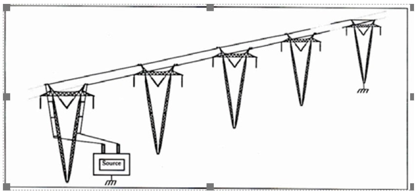
c. DC Current Method
This technology is advantageous for de-icing long transmission lines with large diameter conductors since reactive losses are eliminated. The method has been successfully developed and used in the former USSR for de-icing long 500 kV lines with large bundle conductors. The basic principle consists of forming a closed loop using line conductors, as shown in Fig. 6.
d. On-Load Network De-Icer
Unlike previous de-icing techniques that require disconnecting sections to be de-frosted, this system can be activated without disrupting the network. The On Load Network De-Icer (ONDI) relies on use of a special three-phase transformer called a phase-shifted transformer (PST), used to control energy flows on transmission lines. By adequate adjusting phase-shift of the PST, it becomes possible to increase current flow by a factor of four in the line opposite to the PST line while also maintaining voltage in the network during the de-icing period.
e. De-icing by Current Transfer of Bundled Sub-conductors Through Contactor Devices
The principle of this technique is to transfer the current flow in all the bundled conductors to a single sub-conductor during a de-icing sequence. Thus, for a 4- bundled conductors, for example, the current flowing in a sub-conductor is multiplied by four and the joule losses by 16. This process allows to generate enough heating for ice melting. The process is repeated at regular intervals until all sub-conductors are clear of ice.
Ground Wire De-icing by Joule effect
In order to heat the ground wires for de-icing by the Joule effect, it is necessary to first electrically isolate them from towers, as shown in Fig. 7. The de-icing current can then be supplied by a voltage transformer. With this method it becomes possible to de-ice several kilometers of ground cables. In remote areas, it is also possible to use an auxiliary diesel generator to de-ice ground cables in strategic line sections, such as river crossings.

Mechanical Techniques
Compared to thermal de-icing techniques, mechanical de-icing has the advantage of being easy to use and allowing timely and rapid intervention of critical sections of an overhead network. In addition, these methods require 100 times less energy.
Generally, most mechanical methods are based on breaking the ice by scraping or on releasing energy from shock waves or vibrations to break and pull off ice.
a. Scraping Methods
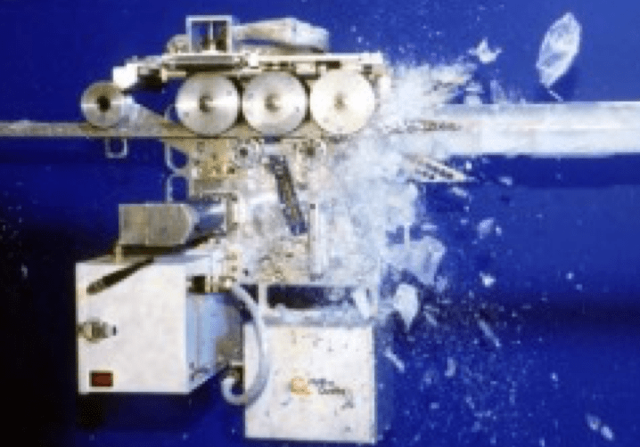
One of the frequent methods to release ice from conductors is using a rope to which scrapers, rollers or cutters thrown over the conductor are attached. The traction force for pulling the rope is applied manually by linemen or other trained personnel or by motorized equipment. More recently, after the 1998 ice storm in Québec, a high traction robot called ROV (Remotely Operated Vehicle) was developed by researchers at Hydro-Québec. This compact device was successfully tested on 315 kV energized conductors. The ice-scraping tool is comprised of a set of steel blades mounted on the ROV (see Fig. 8).
b. Shock Wave Methods
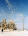
Since ice is brittle at high strain rates (>10-3 s-1), a relatively low mechanical energy applied over only a short time to iced conductors or ground wires can cause ice breakage and shedding. For example, one of the first methods to create a shock wave for de-icing conductors accessible from the ground is to manually hit them with an insulated pole, as shown in Fig.9.
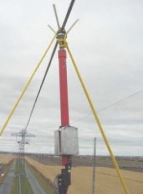
Following the 1998 ice storm, Hydro-Québec developed a portable shock wave de-icing device for ground cables, called the De-icer Actuated by Cartridge (DAC). This device (see Fig.10), which is fully operated from the ground, consists of using a portable cylinder-piston equipped with blank cartridges that can be remotely fired to create shock waves. Hydro-Québec tested a method of de-icing of bundled conductors by generating short-circuit faults involving twin or quad conductors at rated voltages of 315 kV and 735 kV. The electromagnetic forces induced by the short-circuit currents following through the conductors create the oscillatory movement of conductors forcing them to knock against each other and de-ice the span, as shown in Fig.11. Impact studies on the Hydro-Québec grid revealed that this method could be applied to 315 kV lines but only in case of emergency during severe ice storms
c. Vibrating Devices
The principle of these techniques is based on generation of sustained vibrations of conductors or earth wires by devices connected to them to release ice or snow.
One of the vibrating devices, called Automatic Ice Control (AIC), is permanently installed at mid span. It comprises a current transformer, a camera, different sensors for ice detection, a control box with a HF emitter/receiver, and a commercial electromagnetic vibrator, all placed in a rigid protective housing (see Fig.11).
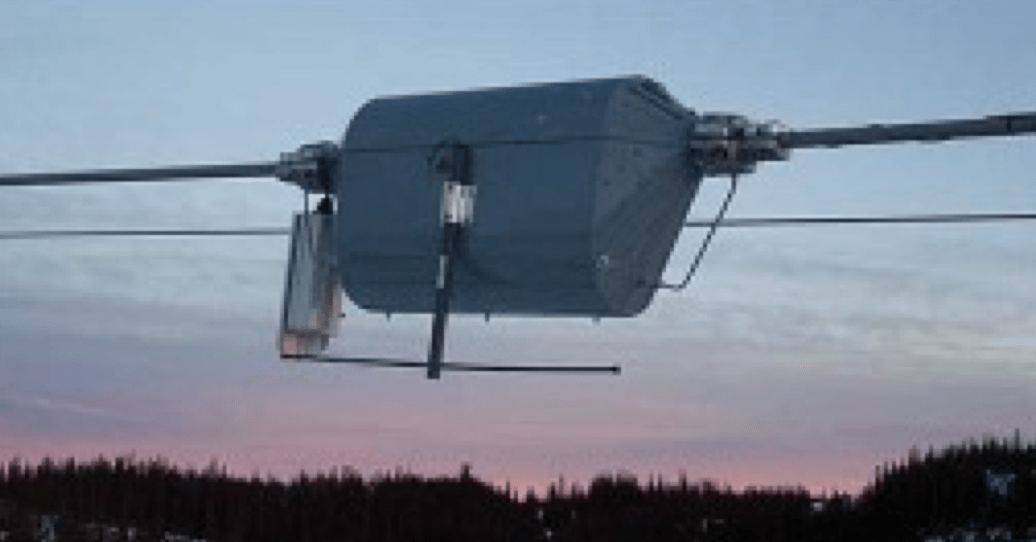
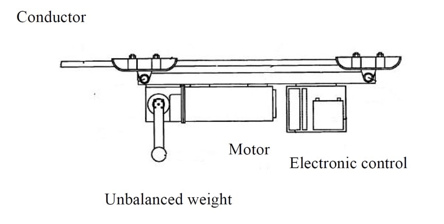
The second vibrating apparatus, called ice-shedder (Fig. 12) is comprised of a motor activating an unbalanced weight whose imbalanced motion is tuned to the natural frequency of the span. This device can be easily installed and driven by power from the conductor or from an external source. Special precautions should be taken when using vibrating devices for de-icing purposes since strong oscillations of conductors or ground wires can cause long-term mechanical damage to power line components.
Use of Passive Devices
Passive devices take advantage of natural forces such as wind, gravity or solar radiation to limit ice or snow loads on conductors and ground wires. Use of some special devices, equipment, conductor stiffness, configuration or span length could influence ice and snow loads and avoid the formation of uniform and circular shape, thus facilitating their shedding. Some of these methods have been already successfully used.
a. Use of Vibrating Devices Anti-Torsion Devices
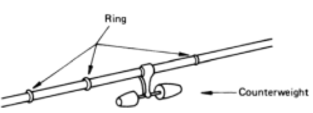
One of these methods consists of using anti-torsion devices such as counterweights (see Fig.13), inter-phase spacers and spacer dampers to increase torsional stiffness of conductor spans so as to limit their rotation. Such measures can prevent formation of cylindrical deposits of wet snow, thus facilitating its shedding by gravity and wind forces.
b. Use of Rubber or Plastic Rings, Wires or PTFE Tapes
Another method to reduce wet snow accumulation is use of rubber or plastic rings, equally spaced, around the conductors. As seen in Fig. 14 (top), snow tends to accumulate on the top of the conductor and slide down along the direction of the strands. The rings (Fig. 14, middle) cause the sliding wet snow to shed as it impacts. A wire wound to the conductor in the opposite direction to the strands can have the same effect as rings (Fig. 14, bottom). PTFE tapes wound to the conductor can also have the same effect.
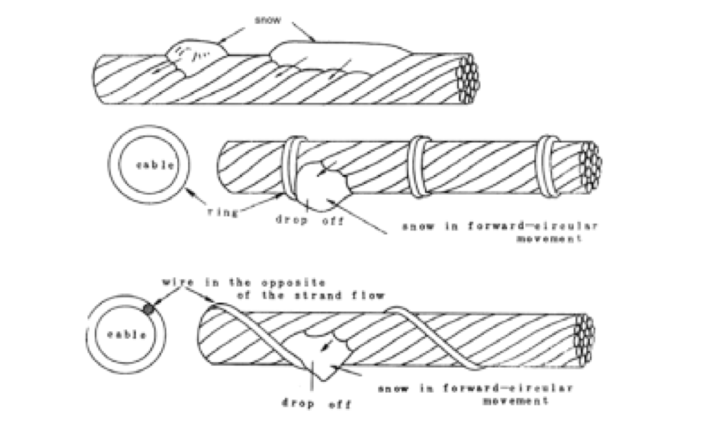
In Japan, except for Okinawa where there is no snow, all overhead lines are equipped with snow rings. Overhead lines with single conductors are also equipped with counterweights, as shown in Fig. 15.
Line Design Approaches
These approaches, considered as the best prevention techniques, should be complementary to above-mentioned mitigation options for superior and more effective protection of overhead lines under icing.
Improved Line Routing
Line route selection is the first optimization step that should be carried out during a transmission line project. In this regard, statistical data on icing are valuable to prevent passing high risk zones when designing and constructing a new line.
Profile of Conductor, Diameter, Stiffness & Bundle Configuration
Conductor diameter and its surface roughness are two parameters that influence ice accretion and shedding. A smaller diameter conductor, with a similar torsional stiffness, collects less ice than a bigger conductor diameter. Also, a smoother surface decreases ice adhesion to the conductor and reduces convection heat transfer to the surrounding air. Taking these in consideration, under the same conditions, a conductor such as a compact trapezoidal strand with a smaller diameter and smoother surface takes less time to shed ice comparing to an equivalent standard stranded conductor. The number of conductors in a bundled configuration is another factor influencing ice and snow accretion load and time of shedding. On one hand, an increase in number of conductors will cause an increase in accretion loads. On the other, it causes decrease in the shedding time since it provides higher rotational stiffness that prevents formation of cylindrical ice. Use of a single rigid conductor under icing conditions seems to be a better choice than bundled conductors of slightly smaller diameters. In any case, more laboratory and field investigations are necessary to clarify the role of conductor diameter, shape, surface roughness and rigidity as well as number and configuration of bundled conductors and span length, in order to clarify the impact of all these parameters on ice and snow loads and time of shedding.
No Ground Wire
This solution can be considered in regions prone to icing where lightning is infrequent. Use of lightning arresters might also be of interest to replace ground wires to protect overhead lines against lightning.
Increased Design Ice Loads
This approach is a generally good solution for increasing reliability of transmission under icing conditions. However, this method should ideally be combined with other solutions.
Load Reducing Devices or Mechanical Fuses
Use of such devices could prevent damage caused by heavy ice or unbalanced loads. This method is not generally an efficient de-icing technique but rather a damage reduction approach. For example, automatic release of ground wires under icing conditions has been used with success by EDF in France.
a. Anti-Cascade Towers
There are a number of possible reasons for transient dynamic loads, e.g. rupture of a conductor in a span caused by high intensity wind, heavy ice or snow accumulation or by sudden ice shedding. The dynamic loads created by supporting tower collapses under such conditions will increase the forces on adjacent or subsequent towers giving rise to multiple tower failures. Integration of anti-cascade towers in a line can limit the extent of possible damage caused by a winter storm, thus keeping repair costs at a reasonable level.
b. Underground Conductors
Use of underground cables to resolve problems caused by ice accretion on overhead lines could be considered a good solution, especially for distribution lines. Advancements in cable technology make this option possible for higher voltage levels as well. Underground cables are also well supported by the public from the aesthetic point of view.

Mitigation Options Related to Insulator Icing
Various remedial methods have been developed to improve reliability of insulators exposed to icing.
Insulator Dimension & Configuration
Increased Dry-Arc Distance
Test results show that the critical flashover voltage of iced- and snow-covered insulators increases with increase in dry-arc distance. This correlation is linear for insulator length ranging from 0.3 to 3 m. This option remains the most reliable way to improve insulator performance under icing conditions.
Increased Leakage Distance
Contrary to dry-arc distance, increasing the leakage distance as a remedial measure becomes less effective under moderate and heavy ice accretion that bridges the inter-shed insulator spacing. However, this measure can be efficient under cold fog conditions, where a thin ice film is formed along the leakage distance. Retrofit of insulators with increased leakage distance is only useful in areas where ice and snow accretion is not severe.
Insulator Diameter, Shed Size & Inter-Shed Spacing
Insulator diameter, shed size and inter-shed spacing are other important parameters influencing the amount and the level of ice and snow accretions as well as the level of shed-spacing bridging. Generally, flashover performance of insulators is better with a smaller shed diameter and larger shed spacing.
Combining Insulators with Different Diameters
Combination of insulators of different diameters, such as illustrated in Fig. 16, increases effective shed-to-shed spacing. Under a certain range of icing conditions, this retrofit option will perform better than standard profiles. This convenient option can be applied to both existing lines and new designs.
Insulator Orientation
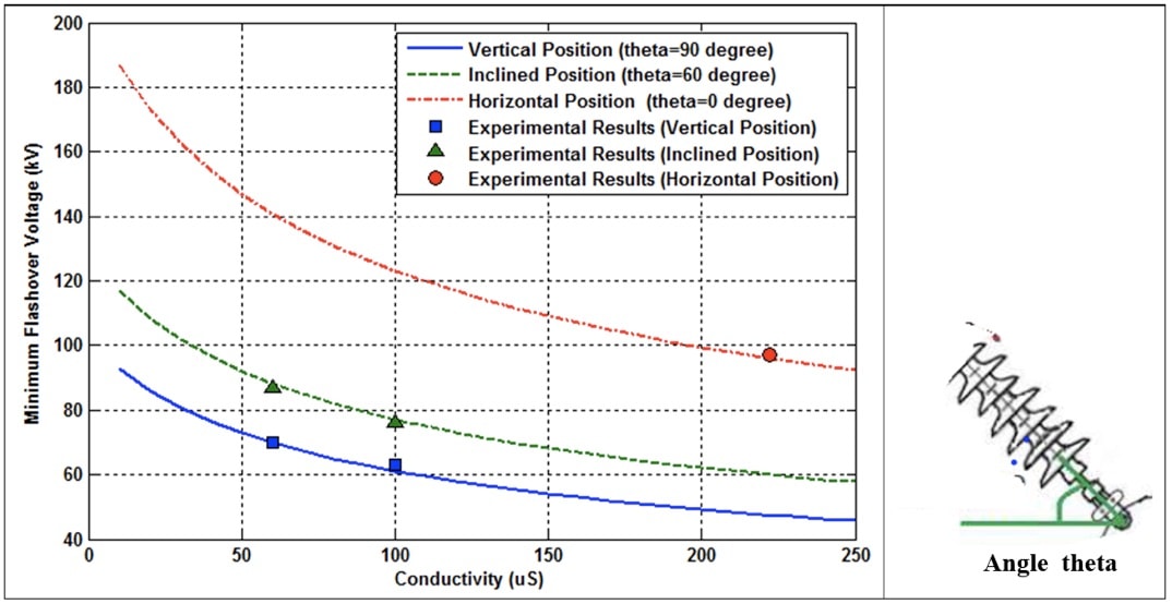
Under icing conditions, horizontal string and V-string insulators are proven to perform better than vertical insulators. This is mainly because much more ice is needed to achieve full bridging of these insulator strings compared to vertical strings. Laboratory tests and mathematical modeling have shown that minimum flashover voltage, VMF, of a horizontal string of four discs under heavy icing condition is about 60% higher than that of the same string at an inclined position and 100% higher than for the vertical position (see Fig. 17).
Accessories
a. Booster Sheds & Creepage Extenders
These accessories, which are used to protect bushings and station post insulators against wetting or contamination flashover, have also proven efficient to provide shelter during ice accretion. Each booster shed can create an ice-free zone (air gap) long enough to increase the flashover strength by 10 to 20 kV (see Fig. 18).
b. Grading rings
Application of corona rings (see Fig.19a) can degrade rather than improve flashover performance of an EHV post station insulator under icing conditions. Results have shown that uniform electric field of an effective corona ring on the insulator surface tends to promote full ice bridging rather than forming air gaps near the high voltage terminal, as shown in Fig.19a. When the upper surfaces of corona rings are covered with a fine metallic mesh, air gaps form near the rings (see Fig. 19b), leading to improved flashover performance. Booster sheds, however, perform this function better and at lower cost.
(a) with grading ring (b) with modified, screen-covered grading rings.
Surface Material
a. RTV Silicone Coating
RTV coatings, developed for improved contamination flashover performance, have also been used as a countermeasure under icing conditions. In cold-fog conditions (very light icing), for example, an increase of about 25% in flashover strength per meter of leakage distance is gained when an RTV silicone coating is applied to porcelain insulators. However, for heavy icing causing icicle bridging of insulator shed spacing, RTV is not effective and cannot reverse the situation. In fact, ice is retained for a longer period on RTV-coated porcelain during the dangerous melting phase. Thus, effectiveness of these coatings to prevent insulator icing flashover is questionable.
b. Semi-Conducting Glaze
The use of semi-conducting glaze insulators under icing conditions offers several benefits. Firstly, low leakage current in the semi-conducting layer, normally around 1 mA, heats the insulator surface above ambient temperature and can help prevent frost formation. The resistive leakage current can also improve voltage distribution along the insulator, which in turn promotes formation of more uniform ice accretion. The relatively uniform voltage stress along the insulator also delays arcing activity across ice-free zones or dry bands in the case of contamination. Both laboratory tests and field exposure of semi-conducting post insulators have shown that these insulators develop large ice-free zones during melting periods which leads to higher flashover strength compared to normal glaze. These insulators have therefore proven highly effective in mitigating icing problems. Direct comparison of performance of conventional and semi-conducting glaze insulators for a 2.0 m dry arc tested under heavy ice conditions showed an improvement of about 20 percent.
c. Super-Hydrophobic Coatings
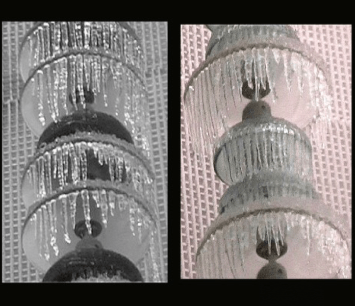
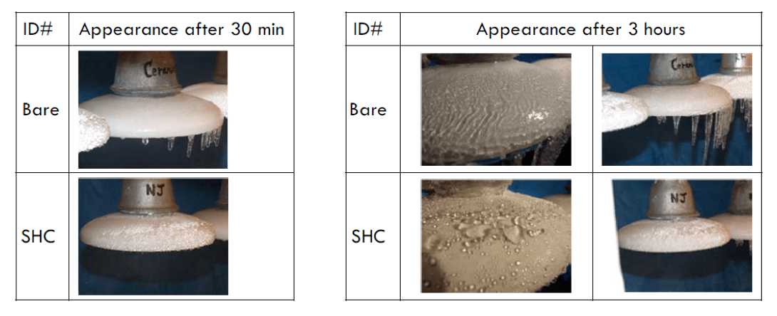
Super-hydrophobic coatings (SHC) with self-cleaning and ice-phobic properties are attractive to improve the flashover performance of insulators under pollution as well as under icing conditions. These coatings with static water contact angle of more than 150˚ and a hysteresis contact angle of less than 10˚ can be achieved by a combination of low surface energy materials having a micro-nanostructured surface. A review of such coatings with potential application to outdoor insulators is reported in CIGRE TB 631. Fig. 20 shows an example of the effectiveness of a SHC in reducing ice accretion on insulators. As can be seen, unlike on the uncoated insulator, no icicles formed on the coated insulator even after 3 hours of icing exposure. This can be explained by shedding of accreted ice from the coated insulator surface before icicles could form.
Recently, a technique, using direct replication method, was developed to produce micro-nanostructured silicone rubber surfaces by compression molding and injection molding systems with application to polymeric insulators. The replicated silicone rubber surfaces tested in this project displayed a contact angle CA>160˚ and a contact angle hysteresis CAH <10˚. The self-cleaning and ice-phobic properties of these surfaces has been successfully verified on a laboratory scale. Research is presently continuing at the University of Québec in Chicoutimi in view of practical application. d. Semi-Conductive RTV Coatings
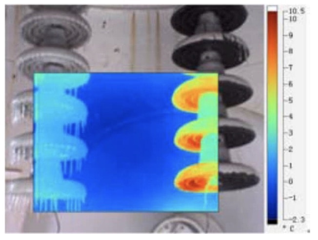
In a laboratory research study, RTV coatings were enhanced with carbon doping, making them semi-conductive with sufficient current flow to prevent ice formation, or by blending them with sub-micrometer scale materials rendering them superhydrophobic, self-cleaning and ice-phobic. Fig. 21 shows an example of using a semiconducting RTV as an anti-icing coating. In this figure, ice was artificially accreted on both clean and contaminated insulators. The semi-conductive silicone rubber coating was applied only to the bottom side of the insulator to eliminate the power loss when there is no precipitation. For the semi-conductive coated string, there were no icicles and no ice covering the surface of the insulators. Also, the coated string showed an obvious surface heating effect. The temperature was about 16°C in the area near the cap and pin but about 0°C in most other parts.
Reduced System Voltage
Reducing transmission system operating voltage during critical ice or snow conditions can be an effective way to lower insulator flashover probability. In one case study, a 5% reduction in operating voltage with 50 parallel insulators under full ice bridging decreased flashover probability from 49.5% (maximum operation voltage) to 11.7%. A voltage reduction of 10%, if available, would have decreased flashover probability down to only 1.2%.
Insulator Washing
Washing energized ice-covered insulators with hot pressurized water has been successfully tested under laboratory conditions. Also, long-term insulator washing during winter using de-ionized water as an electrical barrier has been successfully tested by several utilities in North America as well as Japan.
Conclusions
Icing of overhead power network equipment, including conductors, ground wires and insulators, occurs in many regions of the world and can result in serious failures and damage with major socio-economic consequences. Such effects are aggravated by excessive ice accretion combined with the force of wind giving rise to dynamic phenomena such as galloping and jumping of conductors caused by sudden ice shedding. Despite great progress in research, some phenomena related to ice adhesion, accretion and shedding are still not fully understood. A better understanding of these phenomena would lead to more appropriate protection of power networks during winter conditions.
Various approaches to mitigate the effects of icing on power network equipment, including anti-icing, de-icing, passive devices and line design are overviewed. The anti-icing methods are used to prevent or reduce ice or snow accretion, and mainly consist in using passive and active coatings. New technologies based on the use of ice-phobic materials have a great potential for future applications. The development of efficient, durable and cost effective ice-phobic coatings still needs great R&D efforts. As concerns active coatings almost no significant progress has been made during the past decade. The few previously proposed concepts such as ones based on ice electrolysis and injection of a pulsed current into a conductive coating are likely inefficient or unpractical. One of the active methods presently in use and efficient for wet snow melting is based on the use of a ferromagnetic coating. However, application of this technique for conductor ice melting would require further R&D effort. The efficiency of other potential active coatings based on using materials such as piezoelectric films or electro-active polymers still needs to be demonstrated.
As concerns de-icing techniques, these are used to remove ice or wet snow accretion on conductors or ground wires during or following an icing event. Generally, thermal and mechanical approaches are used to this end. Many utilities have adopted thermal methods based on the Joule effect for de-icing conductors and ground wires on a large-scale and countries have been using these methods for almost a century. For a thermal de-icing strategy to be efficient, however, an adequate detection and monitoring of evolution of ice/snow build-up is necessary, which would still require further R&D. On the other hand, mechanical methods, needing shorter de-icing times compared to thermal methods, are preferred by utilities for the protection of shorter strategic line sections. Mechanical methods are well suited to reduce the risk of the damage or collapse of towers in extreme emergency situations.
In regard to protection of ground wires against icing, this remains one of the important issues and concerns in cold climate regions. Nevertheless, few existing methods, such as removing them in low-risk icing areas, seem to be operational for application. In high-risk icing areas, ground wires could be replaced with lightning arresters to protect overhead lines against lightning.
Techniques based on special devices, equipment, conductors with high stiffness or with improved configuration or span length, have proven to limit ice or snow loads. Some of these devices and equipment, presently in use, can prevent formation of uniform and circular shapes, thus facilitating shedding.
Flashover across insulators under ice and snow conditions, combined sometimes with pollution, is another source of failure. Risk of flashover can be reduced in several ways depending on icing and pollution severity. For light ice accretion with high surface pollution created under cold fog conditions, RTV silicone coating has been found efficient. Under more severe icing conditions, solutions such as substituting insulators with others with improved profiles or with semi-conductive glaze can be adopted. Under heavy icing conditions and very low contamination, the use of devices such as booster sheds was shown to considerably improve the electrical performance of substation insulators. Another solution consists in washing the insulators more frequently during winter or in constructing the line and substations with insulators having longer dry-arc distance. Much progress has been achieved in surface engineering and superhydrophobic coatings with self-cleaning and ice-phobic properties with potential applications to ceramic and non-ceramic insulators. Further efforts in R&D are necessary to find efficient and cost effective techniques to protect insulators against flashover problems under icing, pollution or a combination of them.
References
[1] CIGRÉ TB 344, “Big storm events: What we have learnt”, April 2008
[2] M. Farzaneh, Ed., “Atmospheric Icing of Power Networks”, Springer, Berlin, August 2008, 320 p
[3] CIGRÉ TB 179, “Guidelines for Field Measurement of Ice Loadings on Overhead Power Line Conductors”, August 2000.
[4] O. Nigol, G.J. Clarke & D.G. Havard, “Torsional stability of bundle conductors”, IEEE Paper No. F77224-9, January 1977.
[5] M. Farzaneh & W.A. Chisholm, Insulators for icing and polluted environments, IEEE Press series on Power Engineering, IEEE/John Wiley, New York, 680 p. October 2009
[6] S. Yoshida & K. Naito, “Survey of Electrical and Mechanical Failures of Insulators Caused by Ice and/or Snow”, CIGRE WG B2.03 Report, Electra, No. 222, pp. 22-26, 2005.
[7] M. Farzaneh & W.A. Chisholm, « 50 Years of Icing Performance of Outdoor Insulators ». IEEE Electrical Insulation Magazine, vol. 30, no. 1, January/February 2014, pp. 14-24
[8] C. Laforte & A. Beisswenger “Icephobic Material Centrifuge Adhesion Test”, Proc. of 11th International Workshop on Atmospheric Icing of Structures, Montréal, 2005, pp. 1-6
[9] CEA De-Icing Techniques Before, During, and Following Ice Storms, March 2002, pp. 1-137.
[10] M. Farzaneh & C. Volat, “Anti-icing and De-icing Techniques for Overhead Lines”, Chapter 6, in Atmospheric Icing of Power Networks, Springer, Berlin, August 2008, 320 p
[11] CIGRE WG B2.44, “Coatings for Protecting Overhead Power Network Equipment in Winter Conditions”, TB 631, September 2015.
[12] V.F. Petrenko, “Systems and methods for modifying ice adhesion strength”, U.S Patent 6027075, 2000.
[13] CIGRÉ WG B2.29 “Systems for prediction and monitoring of ice shedding, anti-icing and de-icing for overhead lines”, CIGRE Technical Brochure #438, December 2010.
[14] V.F. Petrenko, C,R, Sullivan, “Pulse electrothermal deicier for power cable”, International Patent 2005083862, 2005
[15] A. Leblond, Y. Asano and M. Isozaki, “Performance Study of LC-Spiral Rods Under Icing Conditions”, Proc. of 13th International Workshop on Atmospheric Icing of Structures, Andermatt, September 2009
[16] Igor Gutman, Johan Lundengård, Vivendhra Naidoo, Boris Adum, “Technologies to reduce and remove ice from phase conductors and shield wires applicability for Norwegian conditions”, International Workshop on Atmospheric Icing of Structures, Reykjavik, Iceland, June 20191, pp 1-9.
[17] P. Prud’Homme , M.O. Roux, P. Guilbault, P.A. Séguin and E. Hounkpatin E, “Determination of Current Required to De-Ice Transmission Line Conductors”, Proc. of 11th International Workshop on Atmospheric Icing of Structures (IWAIS 2005), Montréal, June 2005
[18] Y. Motlis, “Melting Ice on Overhead-Line Conductors by Electrical Current”, CIGRE SC22/WG12 document, draft no. 4, revised for the WG12 Meeting, Paris, 2002
[19] M. Granger, A. Dutil, A. Nantel, S. Laurin S (2005), “Performance Aspects of L´evis Substation DC De-Icing Project”, Proc. of 11th International Workshop on Atmospheric Icing of Structures, Montreal, Canada, 2009, pp. 1–6
[20] J. Brochu , R. Cloutier and A. Bergeron, “On-Load Network De-Icer for HV Transmission Lines”, Proc. of 11th International Workshop on Atmospheric Icing of Structures (IWAIS 2005),Montréal, June 2005
[21] P. Couture, “Switching Modules for the Extraction/Injection of Power (Without Ground or Phase Reference) From a Bundled HV Line”, IEEE Trans. Of Power Delivery, Vol. 19, July 2004
[22] M. Bourdages , “Ground Wire De-Icing by Joule Effect”, Proc. International OPGW Symposium, Montreal, Canada, May 2000
[23] J.L. Laforte, M.A .Allaire and D. Asselin, “État de l’art du déglaçage des conducteurs et des câbles aériens”, Rapport HQ-94-01, Hydro-Québec, 105 p., December 1994
[24] S. Montambault, J. Côté and M. St-Louis, “Preliminary Results on the Development of a Teleoperated Compact Trolley for Live-Line Working”, Proc. 9th International Conference on Transmission and Distribution Construction, Operation and Live-Line Maintenance (ESMO 2000), Montréal, , 2000, pp. 21-27
[25] A. Leblond, B. Lamarche, D. Bouchard, B. Panaroni and M. Hamel, “Development of a Portable De-Icing Device for Overhead Ground Wires”, Proc. of 11th International Workshop on Atmospheric Icing of Structures (IWAIS 2005), Montréal, June 2005.
[26] M. Landry, R. Beauchemin and A. Venne, “De-icing EHV Overhead Transmission Lines using electromagnetic forces generated by moderate short-circuit currents”, IEEE Canadian Review, pp. 10-14, Spring 2001.
[27] R. Hansen, “Means and Method for Removing Extraneous Matter Like Ice/Snow an Overhead Line”, Patent no. US2004065458, 2004.
[28] A. Nourai and R.M., Hayes, “Power line ice-shedder”, U.S Patent no. 6660934, 2003.
[29] P. McComber, “A non-circular accretion shape freezing rain model for transmission line icing”, Proc. of the 9th International Workshop on Atmospheric Icing of Structures (IWAIS 2000), Chester, 2000
[30] C. Blackburn, J.L. Laforte, D. Gagnon and M. St-Louis, “Comparative Study of the Quantity of Rime and Glaze Accreted on Free-Rotating and Fixed Overhead Ground Cables: Effect of Anti-Torsion Device”, Proc. of 10th International Workshop on Atmospheric Icing of Structures, 2002.
[31] N. Higuchi, “Snow Accumulation Prevention Methods”, Hokkaido Electric Power, 1972
[32] H. Saotome, M. Yoshoika and K. Okada, “Countermeasures for Snow Accretion on Conductors”, Proc. of the 4th International Workshop on Atmospheric Icing of Structures (IWAIS 1988), Paris, 1988
[33] M. Farzaneh, J. Zhang, “A Multi-Arc Model for Predicting AC Critical Flashover Voltage of Ice-Covered Insulators”,. IEEE Trans. on Dielectrics and Electrical Insulation, vol 14, 2007, (6):1401–1409
[34] M. Farzaneh and W.A. Chisholm, “Effects of Ice and Snow on the Electrical Performance of Power Network Insulators”, Chapter 7, in Atmospheric Icing of Power Networks, Springer, Berlin, August 2008, 320 p
[35] E.A. Cherney, “Ice Bridging Flashover of Contaminated 500 kV Line Insulation in Freezing Rain”, Ontario Hydro Report, 1986, 86-80-H
[36] EPRI, “Transmission Line Reference Book 345 kV and Above”, EPRI, Palo Alto, 1982
[37] B. Porkar and M. Farzaneh, “AC Flashover Performance of a Horizontal Insulator String under Heavy Icing Conditions”, Proceedings of the 20th International Symposium on High Voltage Engineering, Buenos Aires, Argentina, August 27 – September 01, 2017
[38] H. Akkal, C. Volat and M. Farzaneh, “Improving Electrical Performance of EHV Post Station Insulators under Severe Icing Conditions Using Modified Grading Rings”, IEEE Transactions on Dielectrics and Electrical Insulation, Vol. 20 , No. 1, pp. 221 – 228, Feb. 2013.
[39] W.A. Chisholm, “Ten Years of Application Experience with RTV Silicone Coatings in Canada”, Proc of INMR World Conference & Exhibition on Insulators, Arresters & Bushings, Hong Kong, no 17, pp. 1–20, 2005
[40] M. Farzaneh and S. Brettschneider, “Étude de la tension de tenue des isolateurs de postes en présence de glace atmosphérique en vue d’ un choix approprié de type et configuration d ’ isolateurs de poste à 735 kV, Volume 1, Étude en vue du choix d ’ isolateurs pour le futur poste Monté régie, ” Report presented to Institut de Recherche d ’ Hydro – Québec (IREQ). September 2001
[41 T. Hayashi, T. Nakachi, K. Kondo, M. Maeda, N. Sugawara and D. Nishimura, “Anti-icing performance of insulators by special surface treatments”, 18th International Symposium on High Voltage Engineering, August 2013.
[42] K. Maghsoudi, R. Jafari, G. Momen, M. Farzaneh, “Fabrication of Polymer Micro-Nanostructured Surfaces: Mold Inserts, Processing Parameters and Demolding”, Polymer Surfaces: Fabrication, Modification and Applications, Chapter 1, November 2018.
[43] K. Maghsoudi, R. Jafari, G. Momen, M. Farzaneh, “Direct replication of micro-nanostructures in the fabrication of superhydrophobic silicone rubber surfaces by compression molding”, Applied Surface Science, Vol 458, pp. 619-628, November 2018.
[44] X. Wei, Z. Jia, Z. Sun, Z. Guan, and M. MacAlpine, “Development of Anti-icing Coatings Applied to Insulators in China”, IEEE Electr. Insul. Mag., vol. 30, pp. 42- 50, Feb. 2014.
[45] V. Sklenicka and J. Vokalek, “Insulators in icing conditions: Selection and measures for reliability increasing”, Proc of the 7th International Workshop on Atmospheric Icing Structures, Chicoutimi, pp. 72–76, 1996