For the first time ever, long land-based transmission links are being implemented with extruded cable systems at a nominal voltage of ±525 kV.
This edited contribution to INMR by Prof. Dr. Ronald Plath of the Technische Universität Berlin deals with HVDC corridor projects under construction in Germany and reviews after-installation testing according to the relevant standards. In this case, the German transmission system operators are planning to perform not only DC but also AC voltage testing in combination with on-site partial discharge measurements.

Background
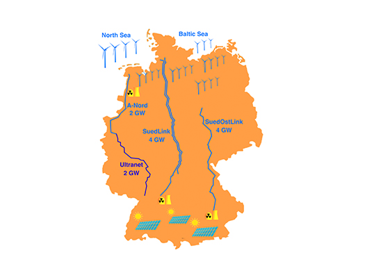
The German energy transition to renewables provides for the planned phase-out of both nuclear energy and coal. The increasing share of renewable but volatile energies will require reinforcing the existing 380 kV AC grid. Onshore and offshore wind generation is located mainly in the north while solar energy is mainly in the south. Main load centers are in the southwest and the sites of the de-commissioned nuclear power plants provide powerful access points to the grid. The three HVDC corridor projects under construction will therefore improve balancing of electricity from renewables while ensuring electricity supply after the last three nuclear power plants are shut down.
Originally, it was planned to build the corridor projects as overhead lines. While there was widespread public approval for the energy transition, protests quickly arose against the planned new overhead lines. In 2015, the federal government therefore prioritized cables over overhead lines, in the process accepting the related higher costs as well as the need to completely replan the corridor projects. However, at the time, only 320 kV HVDC extruded cables were available on the market. Moreover, there was only limited operating experience available for such cables, mainly from application as export cables for offshore wind farms and in a few land projects.
Fortunately, 2017 saw publication of the first edition of IEC 62895 High Voltage Direct Current (HVDC) power transmission cables with extruded insulation and their accessories for rated voltages up to 320 kV for land applications – Test methods and requirements.
In order to virtually halve the number of cables, and particularly joints, needed for the planned transport capacity, a nominal voltage of 525 kV would be preferred. Since extruded HVDC cables at 525 kV were not yet qualified and the corresponding standard was limited to 320 kV, tests of 525 kV cable systems were initially performed based on the CIGRE TB 496 recommendation.
In 2018 and 2019, several pre-qualification (PQ) tests on HVDC 525 kV extruded cable systems (cable, outdoor terminations and joints) were successfully passed. These tests did not yet include gas-insulated switchgear interfaces because no type test certificates were yet available for this type of accessory. After much discussion, DIN IEC 62895 (including the German Annex) was published in 2019, especially to extend the scope from 320 kV to 525 kV. Based on the successful PQ tests, German TSOs made the decision in late 2019 to go with HVDC 525 kV extruded cables for the corridor projects. Most awards were then made in 2020, with total cost for the HVDC cable corridor projects estimated to fall between 50 and 70 billion €. In August 2020, the world’s first type test approval for HVDC 525 kV gas-insulated switchgear interface was successfully passed.
Commissioning of the HVDC cable corridor projects is scheduled for 2025 at the earliest, with SuedLink, the longest cable system running about 700 km. Possible delays may push this back to 2028.

525 kV HVDC Cable System
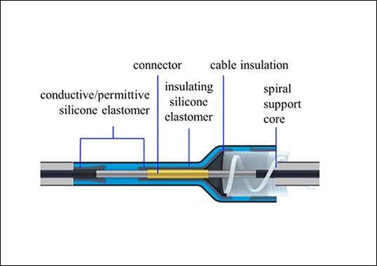
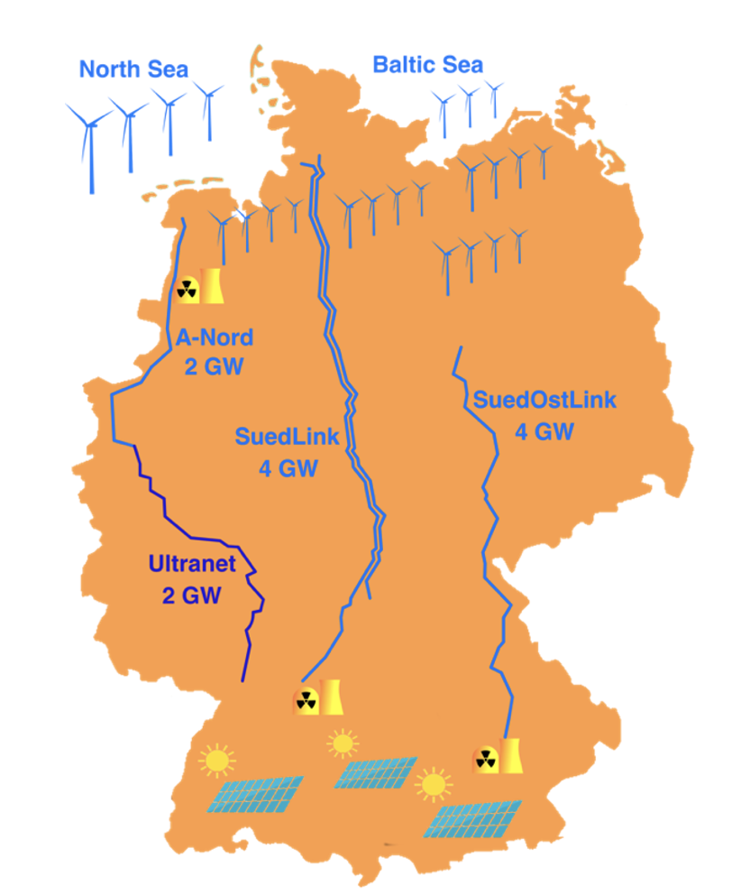
The corridor projects cable systems will consist of HVDC extruded cables, joints and outdoor terminations. The 525 kV HVDC cable design will be similar to common HVAC cable designs, with the main difference being in the conductor, which does not require AC loss optimization even for the highest cross-sections (see Fig. 2).
Three different polymeric insulating materials are being used for the main insulation of these 525 kV HVDC cables:
• cross-linked polyethylene (XLPE);
• polypropylene (PP ); and
• XLPE with inorganic filler.
Only filled XLPE is suitable for operation in “classical” HVDC systems with LCC converters, where direction of load flow is changed by the polarity of the DC voltage. With SVC converters, polarity reversal of voltage is not necessary.
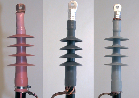
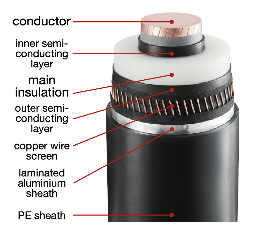
Unlike the case for long AC cable systems, HVDC cable systems do not require cross-bonding to minimize screen losses. Accordingly, only straight through joints are needed (see Fig. 3).
Nonetheless, screen interruption joints with external and accessible screen connections are to be installed every 5 km to 12 km (see Fig. 3). The design of these joints is similar or even identical to AC cross-bonding joints, thereby allowing grounding of the cable screen and, if needed, access for sheath testing and fault location. This will also allow for distributed PD detection. Inductive PD sensors at the earthing connection of straight through joints with additional earthing provide very low PD sensitivity.
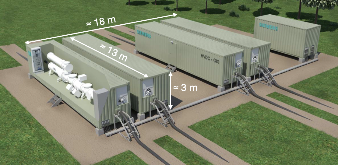
Due to the exceptional length of the cable systems in these corridor projects, each will consist of sections supplied by different manufacturers. Due to constraints in after-installation testing, the length of each cable section will be about 100 km long. While the obvious choice to connect two cables is a joint, special transition joints would be required to connect HVDC cables from two different manufacturers. Depending on number of manufacturers, transition joints would therefore have to be developed for all combinations. In addition to the huge development effort required, this would create a nightmare for spare parts logistics. For these reasons, each cable section is to be equipped with outdoor cable terminations that can easily be connected to the cable termination of the next cable section. This will also allow for separate testing of each cable section, which is necessary for both technical and commercial reasons. The facility for connecting two cable sections is termed a “cable transition station”. Each such 525 kV HVDC outdoor cable transition station will be about the size of a small switchyard (see Fig. 4).
To minimize impact on the surroundings, cable transition stations could alternatively be installed underground. However, this would require correspondingly large and elaborate buildings. The most compact solution for connecting HVDC cable systems from different manufacturers would be to use gas-insulated switchgear interfaces in back-to-back configuration (see Fig. 5). With two integrated disconnect switches and a suitable outdoor test bushing installed only during voltage testing, separate testing of each cable section after installation would be feasible without difficulty. However, due to the late type approval and still missing pre-qualification test certificate, this solution is not expected to play a role for the first of the corridor projects.
IEC 62895:2017
IEC 62895:2017 covers HVDC extruded cables as well as their accessories for rated voltages up to 320 kV for land applications. In Ch. 16 “Electrical tests after installation”, this standard demands a DC oversheath test as well as a DC insulation test with 1h negative polarity DC voltage, regardless of polarity of the voltage in operation.
DIN IEC 62895:2019
DIN IEC 62895:2019 is published in German and the below citations from this standard have been translated by Prof. Dr. Plath. This standard is not a direct translation of IEC 62895:2017 and an annex has been added that extends its scope from 320 kV rated DC voltage to 525 kV. In regard to after-installation testing, this annex deviates from IEC 62895 in one relevant aspect: IEC 62895, Ch. 16 Electrical tests after installation, section 16.1 General, paragraph 2 reads:
A DC oversheath test according to 16.2 and a DC insulation test according to 16.3 is recommended.
In DIN IEC 62895, this paragraph is replaced by:
Since installation faults are not reliably detected by DC voltage tests according to 16.3, an AC after-installation test according to 16.3.1 should be carried out, possibly on sections of the cable system.
This paragraph clearly emphasizes the efficiency of (optional) AC voltage testing as opposed to (mandatory) DC voltage testing. For the case of 525 kV HVDC cable systems, the AC test voltage (rms) should be 260 kV (as per Table 1). In this case, the AC peak value of approx. 368 kV lies below the rated DC voltage (i.e. 525 kV). According to DIN IEC 62895:2019, Section 16.3.1, the AC resonant frequency for HVDC cables should be within 10 Hz and 300 Hz, with test duration of 1h.
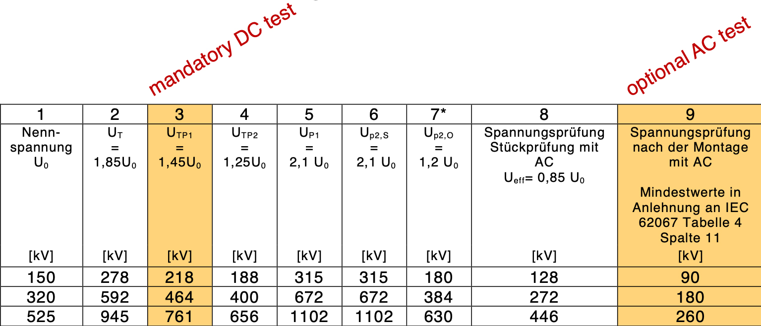
Table 1: Test Voltages for HVDC Extruded Cables*
The HVDC cable corridor projects are designed as ±525 kV bipoles without a separate ground return conductor. During operation, the DC load current flows practically only in the cable conductors, not in the cable screen. However, during voltage testing, the test current (both DC and AC) must flow back through the cable screen to the test voltage source. Due to constraints for maximum cable screen current, testable cable length is about 100 km.
One of the German TSOs plans to perform AC after-installation tests at 380 kV (rms) and a minimum resonant frequency of 20 Hz – in accordance with IEC, (IEC 62067 Ed. 3.0 Power Cables with Extruded Insulation and their Accessories for Rated Voltages above 150 kV (Um = 170 kV) up to 500 kV (Um = 550 kV) – Test Methods and Requirements, 2022.) At a given specific cable capacitance and a limited cable screen current, the testable cable length will be correspondingly shorter, i.e. approx. 34% compared to 100% at 260 kV (rms), 10 Hz. An additional note in DIN IEC 62895:2019, section 16.3.2 recommends performing on-site PD measurements during after-installation voltage testing to increase test efficiency:
NOTE: A sensitive partial discharge measurement as part of the on-site tests can be an efficient addition to the specified voltage tests. On-site PD measurement is therefore the focus of current developments. By integrating sensors into the cable system, the informative value of PD measurement can be significantly increased.

On-Site PD Measurement
According to IEC 60270, PD measurement and calibration is restricted to an electrical circuit represented by lumped capacitances. PD detection at the cable end(s) according to IEC 60885-3 is usually only applicable to factory tests. On site, interference and longer cable lengths require distributed PD measurements to ensure sufficient measurement sensitivity. Distributed PD measurements on cable systems require suitable PD sensors at the cable accessories as well as distributed PD detection and communication (i.e. PD data transmission). For after-installation tests of short duration, e.g. 1h, batteries are sufficient for power supply of the de-centralized PD acquisition units.
If each joint is equipped with a PD sensor and PD measurement frequency is sufficiently high, the focus is only on joints. Interference is very low (low-pass character of pulse propagation) and the signal-to-noise ratio (SNR) would be correspondingly high. This concept ensures selectivity for joint-internal PD.
Singular weak spots in extruded cable systems, e.g. installation faults, can best be detected using a combination of AC voltage testing and accompanying distributed PD measurement. According to present knowledge, this also holds for DC insulation systems. However, it cannot be ruled out that as yet unknown types of defects could be better uncovered by DC than by AC PD measurements, although there is currently no evidence for this. Given current state-of-experience and to minimize risk of overlooking DC relevant defects, DC PD measurements would be recommended in addition to AC PD measurements during AC after-installation testing. If PD measurements were already performed during the AC after-installation voltage test, the additional effort for DC PD measurements during the DC voltage test would be minimal. Of course, for the reasons mentioned above, DC monitoring would be of interest to gain addiitonal experience.
On-Site AC PD Measurements
Distributed PD measurements on AC-EHV cable accessories as part of after installation AC voltage testing have been performed for a long time and can still be called state-of-the-art. Moreover, this method is in accordance with the corresponding note of DIN IEC 62895:2019, section 16.3.2.
However, for HVDC cable sections of 100 km or longer, it would be neither practical (i.e. easy access only to screen interruption joints, not to straight through joints) nor economically justifiable to equip each joint with its own PD sensor. Instead, only screen interruption joints are expected to be equipped with PD sensors.
As a result, there are several straight-through joints without a PD sensor between two screen interruption joints with PD sensors. The concept of selectivity, namely each joint equipped with PD sensor, which has proven successful in EHV AC cable systems, must therefore be abandoned. The PD sensors must now be set to lower measurement frequencies to ‘see farther’ and thus obtain acceptable PD sensitivity for the straight through joints without PD sensors. The previous concept of selectivity is replaced by localization using synchronized two-sided PD detection to estimate pulse time-of-arrival.
These HVDC screen interruption joints must enable PD detection and thus distributed and synchronized PD measurements, at least at every nth joint (recommendation: n ≤ 6, to maintain acceptable PD sensitivity with increasing n). Attenuation and dispersion of PD pulses increases with cable length and inevitably reduces measurement sensitivity that can be achieved due to constraints in physics.
For HVDC accessories with e.g. non-linear field control, AC voltage stress can possibly cause critical dielectric losses that do not occur with DC voltages. Therefore, the manufacturer must agree to the AC voltage test, test voltage level, AC frequency and test duration.

On-Site DC PD Measurements
In principle, DC measurement differs from AC measurement only in a few respects:
• Inductive PD sensors must be suitable for the maximum DC currents, core saturation must be avoided. Capacitive sensors or field sensors (antennas) will work with DC just as they do with AC;
• Depending on DC source, interference can be higher than, for example, AC resonant test systems. In operation, disturbances due to converter operation are predominant;
• It seems trivial: with DC voltages, there is no AC phase correlation and thus no phase-resolved PD (PRPD) patterns. However, sometimes the ripple voltage can be sufficient for AC phase synchronization, which can be helpful in distinguishing converter faults from PD;
• Broadband PD detection combined with transient recorders allows analyzing PD pulse waveform. Current pulse waveform analysis (CPWA), was first mentioned in AC PD measurements on GIS. The waveform can be used to distinguish PD pulses from interference pulses and, in some cases, to reconstruct the pulse propagation path from PD source to PD detection. This has already been done with AC-generated PD pulses. For the rarer DC PD pulses, analysis of pulse waveform gains new importance for de-noising and PD pulse classification;
• In solid-insulated systems, frequency of occurrence of PD under DC stress is usually very low and can include extended periods without any PD activity. However, sudden bursts of PD can occur, which then require immediate high-speed data processing by the PD measuring device.
As mentioned above, there is still no evidence to support preferring DC over AC PD measurements for DC insulation systems.
At DC voltage stress, typical defects in solid insulation such as XLPE or PP show higher PD inception voltage (PDIV) and much lower frequency of occurrence after inception compared to AC voltage stress. Even worse, field-enhancing defects (‘needle-type’), easily detectable with AC PD measurements at moderate voltage level, will eventually not incept up to highest DC voltage levels due to space charge injection, causing local field reduction and thus defect ‘shielding’. Such an accumulation of space charges could be critical if, for example, grounding after a DC voltage test leads to transient local field enhancement and eventually to formation of an electrical tree. In XLPE, once an electrical tree has started, it slowly grows even under DC stress and will finally lead to insulation breakdown. Frequency of occurrence of PD pulses is also very low for DC treeing.
The question arises: what will PD experts conclude from a measurement in which only a few PD pulses (perfectly distinguished from disturbances) occur during a 1-hour DC voltage test? Would this be sufficient to decide whether or not to open or replace a 525 kV HVDC joint or termination?
DC PD Monitoring
A first comprehensive concept for PD monitoring of HVDC extruded cables has already been introduced (see Ref. 34). In general, PD monitoring has two key advantages over short-time PD testing:
• Monitoring covers all operating conditions. For extruded HVDC cables, temperature is of great interest because DC conductivity of the main insulation increases exponentially with temperature. At maximum conductor temperature, this could lead to field inversion, resulting in the highest field stress at the outer semi-conducting layer. At maximum load, the interface between cable and accessories is subjected to higher stress than at ambient temperature. Since after-installation voltage tests are performed at ambient temperature, the dielectrically more critical case is fully covered by PD monitoring only.
• The usual very low frequency of occurrence of PD in solid polymer insulation is not a concern for statistical evaluation of DC PD pulses, considering the practically infinite time for monitoring. Of course, number of interference pulses also increases with acquisition time interval.
It would seem of great importance to consider DC PD monitoring of HVDC extruded cable systems to fill the current experience gap in this field. The legitimate question whether the technical and economic effort for DC PD monitoring is justified can only be answered after the fact. The improved chance of preventing at least some unplanned outages of 525 kV HVDC cables should render this effort worthwhile.
DC PD Interpretation
Evaluation of PD is usually based on a combination of (quantitative) defect localization and (qualitative) defect identification. PD localization for cables is usually done by TDR (time domain reflectometry), time-of-arrival estimation or simply by the concept of selectivity. The output of the localization is the defect position (with limited accuracy). PD localization methods are independent of type of PD-causing voltage stress (AC or DC). In principle, PD localization could be based on a single pulse propagating in a cable system. In practice, however, presence of interfering pulses requires statistical evaluation, which also improves localization accuracy. In the case of cables, PD mapping has proven effective.
For identification of PD, parameters are needed for the most definite assignment to different classes (void, free potential, surface discharges, corona, moving particles, etc.).
For AC, PD classification is based on statistical evaluation on a high number of PD pulses. The most common visualization for this is a PD fingerprint or pattern (PRPD), more precisely histograms showing the cumulated frequency of occurrence of PD pulses correlated to the PD pulse magnitude and AC phase over a given time interval. These patterns have a characteristic appearance depending on defect type, allowing experts or expert systems to identify the type of PD. Depending on defect type, these patterns have a characteristic appearance that enables experts or expert systems to identify the PD cause. If PDs from multiple defects overlap, noise reduction techniques such as CPWA can help ‘isolate’ a particular PD pattern to simplify interpretation. Another visualization of PD is called pulse sequence analysis or PSA. This autocorrelation method is based on amplitude ratio and/or time between two consecutive PD pulses. By contrast to the PRPD pattern, which cannot be generated without AC phase, PSA also works in DC PD. As an autocorrelation method, PSA is highly sensitive to multiple PD sources and interferences.
PSA has been applied to DC PD. Although originally developed only for AC PD, it also works in several DC PD cases, e.g. in gas-insulated systems. However, for DC PD in solid insulation, the small number of PD pulses is highly disadvantageous for any statistical evaluation.

Conclusions
Installation faults occur regardless of type of cable and type of voltage stress (AC or DC). For the foreseeable future, PD measurement is the only effective method to detect and locate singular weak spots. Such singular weak spots in cable systems, e.g. from installation faults, can best be detected with a combination of AC voltage testing with accompanying distributed PD measurement. According to current knowledge this also works for DC insulation systems.
All four German TSOs plan AC testing with PD measurement for the upcoming 525 kV HVDC cable corridor projects. Therefore, certain HVDC cable joints must be equipped with suitable PD sensors to enable PD detection and thus distributed and synchronized PD measurements.
It would be advisable to also measure PD during the DC after-installation voltage test.
DC PD monitoring should be considered on a partial length (section) – at least in the initial phase – to gain experience with operational behavior of the world’s first 525 kV HVDC extruded land cable systems of exceptional lengths.
References
[1] C. Morris and A. Jungjohann, Energy Democracy. Germany’s Energiewende to Renewables, Palgrave Macmillan, 2016.
[2] BMUV, “12-point plan to complete the nuclear phase-out – the position of the Federal Environment Ministry,” 2021. [Online]. https://www.bmuv.de/ fileadmin/Daten_BMU/ Download_PDF/Nukleare_Sicherheit/12_punkte_atomausstieg_en_bf.pdf. [Accessed 26 07 2022].
[3] BMUV, “Frequently Asked Questions on Germany’s coal phase-out,” 2022. [Online]. https://www.bmuv.de/en/topics/climate-adaptation/ climate-protection/ national-climate-policy/translate-to-english-fragen-und-antworten-zum-kohleausstieg-in-deutschland. [Accessed 26 07 2022].
[4] C. Morris, “Germany shuts down next nuclear plant,” 13 Dezember 2017. [Online]. https://energytransition.org/2017/12/germany-shuts-down-next-nuclear-plant/. [Accessed 26 07 2022].
[5] Bundesnetzagentur für Elektrizität, Gas, Telekommunikation, Post und Eisenbahnen, “Bedarfsermittlung 2021-2035. Bestätigung Netzentwicklungsplan Strom,” Januar 2022. [Online]. https://www.netzentwicklungsplan.de/ sites/default/files/paragraphs-files/NEP2035_ Bestaetigung.pdf. [Accessed 26 07 2022].
[6] M. Neukirch, “Grinding the Grid: Contextualizing Protest Networks Against Energy Transmission Projects in Southern Germany,” Energy Research & Social Science, vol. 69, no. 101585, pp. 1-13, 21 05 2020.
[7] IEC, IEC 62895 Ed. 1.0 High Voltage Direct Current (HVDC) power transmission cables with extruded insulation and their accessories for rated voltages up to 320 kV for land applications – Test methods and requirements, 2017.
[8] CIGRE WG B1.32 Technical Brochure 496, “Recommendations for Testing DC Extruded Cable Systems for Power Transmission at a Rated Voltage up to 500 kV,” 2012.
[9] J. Brüggmann, D. Thiele, F. Martin, S. Pöhler, C. Kuhn, T. Schrank, J. Christian and M. Schultheiss, “Prequalification Test of Extruded HVDC 525-kV-Underground Cables,” in CIGRE Sessions, Paper B1-308, Paris, France, 2018.
[10] DIN, DIN VDE 62895 Ed. 1.0 VDE 0276-2895:2019-02 Kabel zur Hochspannungs-Gleichstrom-Übertragung (HGÜ) mit extrudierter Isolierung und ihre Garnituren für Nennspannungen bis 320 kV für Anwendungen an Land – Prüfverfahren und Anforderungen (IEC 62895:2017), 2019.
[11] SWR, “Betreiber konkretisiert Zeitplan. Statt 2022: Wird Stromautobahn SuedLink erst 2028 fertig?,” 02 02 2022. [Online]. Available: https://www.swr.de/swraktuell/baden-wuerttemberg/transnet-stromautobahn-ausbau-verzoegert-100.html. [Accessed 27 07 2022].
[12] T. Hjertberg, V. Englund, P.-O. Hagstrand, W. Loyens, U. Nilsson and A. Smedberg, “Materials for HVDC Cables,” in Jicable HVDC’13 European Seminar on materials for HVDC cables and accessories: Performance, Modelling, Testing, Qualification, Perpignan, France, 2013.
[13] J.-W. Zha, M.-S. Zheng, W.-K. Li, G. Chen and Z.-M. Dang, “Polypropylene Insulation Materials for HVDC Cables,” in Polymer Insulation Applied for HVDC Transmission, Springer, 2021, pp. 77-96.
[14] S. Nishikawa, K.-i. Sasaki, K. Akita, M. Sakamaki, T. Kazama and K. Suzuki, “XLPE Cable for DC Link,” SEI Technical Review, no. 84, pp. 59-64, 2017.
[15] Y. Sekiguchi, “Polymer Composites for Power Cable Insulation,” in Polymer Composites for Electrical Engineering, Wiley IEEE, 2022, pp. 123-151.
[16] 50Hertz Transmission GmbH, “SuedOstLink – Abschnitt A2. Der Trassenverlauf in der Detailplanung,” 2021.
[17] F. Martin and S. Pöhler, “Challenges and Innovations in the German Transmission Grid AC and DC Onshore and Offshore,” in Highvolt Kolloquium, Dresden, Germany, 2019.
[18] M. Kosse and K. Juhre, “Experience in Testing of High-Voltage DC Gas-insulated Systems and Potential Applications for Rated Voltages up to ±550 kV,” in Highvolt Kolloquium, Dresden, Germany, 2019.
[19] IEC, IEC 62067 Ed. 3.0 Power Cables with Extruded Insulation and their Accessories for Rated Voltages above 150 kV (Um = 170 kV) up to 500 kV (Um = 550 kV) – Test Methods and Requirements, 2022.
[20] IEC, IEC 60270:2000+AMD1:2015 CSV Ed. 3.1 High-voltage test techniques – Partial discharge measurements, 215.
[21] IEC, IEC 60885-3:2015 Ed.2.0 Electrical test methods for electric cables – Part 3: Test methods for partial discharge measurements on lengths of extruded power cables, 2015.
[22] CIGRE WG B1.28 Technical Brochure 728, “On-site Partial Discharge Assessment of HV and EHV Cable Systems,” 2018.
[23] A. Abbasi, “Interim Report of WG D1.63: Progress on Partial Discharge Detection under DC Voltage Stress,” in CIGRE Colloquium SCA2/SCB2/SCD1, New Delhi, India, 2019.
[24] H. Ota, M. Ichihara, N. Miyamoto, S. Kitai, Y. Maruyama, M. Fukasawa and H. Takehana, “Application of Advanced After-Laying Test to Long-Distance 275 kV XLPE Cable Lines,” IEEE Trans. Power Delivery, Vol. 10, No. 2, pp. 567-579, 1995.
[25] R. Plath, Ulrich Herrmann, K. Polster, J. Spiegelberg and P. Coors, “After Laying Tests of 400kV XLPE Cable Systems for Bewag Berlin,” in ISH. Int. Symp. on High Voltage Engineering, Paper 5.277.P5, London, UK, 1999.
[26] G. Schröder, S. J. Sutton and R. Plath, “The St. Johns Wood – Elstree Experience — Testing a 20 km Long 400 kV XLPE-insulated Cable System After Installation,” in Jicable, Paper A.2.2, Versailles, France, 2007.
[27] P. Wagenaars, P. A. Wouters, P. C. van der Wielen and E. F. Steennis, “Accurate Estimation of the Time-of-Arrival of Partial Discharge Pulses in Cable Systems in Service,” IEEE Trans. Dielect. Elect. Insulation, vol. 15, no. 4, pp. 1190-1199, 2008.
[28] S. A. Boggs and G. C. Stone, “Fundamental Limitations in the Measurement of Corona and Partial Discharge,” IEEE Trans. Elect. Insulation, vol. 17, no. 2, pp. 143-150, 1982.
[29] A. Matsushita, K. Kato, N. Hayakawa, K. Kawakita and H. Okubo, “Partial Discharge Current Pulse Waveform Analysis (CPWA) for Electrical Insulation Diagnosis of Solid Insulators in GIS,” in IEEE Annual Report Conf. on Elect. Insulation and Diel. Phenomena, 2001, Kitchener, Ontario, Canada.
[30] X. Li, G. Wu, X. Zhang and S. Bian, “Partial Discharge Pulse Shape Detection and Analysis under DC Condition in Typical Defect Models,” in IEEE Annual Report Conf. on Elect. Insulation and Diel. Phenomena, 2007.
[31] A. D. Elben, T. Fechner, X. Lei, R. Plath and M. Zhou, “Modern Noise Rejection Methods and their Applicability in Partial Discharge Measurements on HVDC Cables,” in ICHVE. Int. Conf. on High Voltage Engineering and Application, Athens, Greece, 2018.
[32] J. Pihera, J. Hornak, A. Vobornik, L. Kupka, S. Chladek and R. Haller, “Partial Discharges Pulse Shape Analysis at AC and DC,” in ISH. Int. Symp. on High Voltage Engineering, Budapest, Hungary, 2019.
[33] F. Esterl, R. Plath, C. Freitag, A. Wagner and R. D. Zhang, “Electrical Treeing and Partial Discharges in DC-XLPE under Constant DC Voltage and Repetitive DC Ramp Voltage,” in VDE Fachtagung Hochspannungstechnik, Berlin, Germany, 2020.
[34] E. Winkelmann, I. Shevchenko, C. Steiner, C. Kleiner, U. Kaltenborn, P. Birkholz, H. Schwarz and T. Steiner, “Monitoring of Partial Discharges in HVDC Power Cables,” IEEE Electrical Insulation Magazine, vol. 38, no. 1, pp. 7-18, 2022.
[35] J. Fuhr, M. Hässig, B. . A. Fruth and T. Kaiser, “PD-Fingerprints of some High Voltage Apparatus,” in IEEE Int. Symp. on Elect. Insulation, Toronto, Canada, 1990.
[36] R. Patsch and M. Hoof, “Pulse-Sequence-Analysis, a Way to Get a Better Insight into the Physics of Discharges,” in Int. Conf. on Partial Discharges, Canterbury, UK, 1993.
[37] U. Fromm and E. Gulski, “Statistical Behaviour of Internal Partial Discharges at DC Voltage,” in Int. Conf. on the Properties ans Applications of Dielectric Materials, Brisbane, Australia, 1994.
[38] M. Geske, C. Neumann, T. Berg and R. Plath, “Assessment of Typical Defects in Gas-insulated DC-Systems by Means of Pulse Sequence Analysis Based on UHF-Partial Discharge Measurements,” in VDE Fachtagung Hochspannungstechnik, Berlin, Germany, 2020.
[39] R. Plath, “DC PD Interpretation,” in Highvolt Kolloquium, Dresden, Germany, 2019.