Power distribution networks are changing rapidly as integration of renewables as well as creeping urbanization require updated concepts in power infrastructure. Compactness and size reduction are no longer simply desirable but now a crucial performance requirement. Similarly, downtime has to be minimized while safety aspects are increasingly complex.
This edited past contribution to INMR by experts at Pfisterer in Germany discussed these challenges in the context of their development of next generation cable accessories.


Increasing Transmission Capacity
Urbanization requires a higher transmission capacity that could either be triggered by numbers of consumers or by fluctuations in generation and consumption due to integration of renewables. In addition, energy often has to be transported great distances from points of generation to major demand centers and this requires detailed consideration of power losses.
One approach to reduce power loss is by increased system voltage, as has been achieved over past decades. The first three-phase alternating current transmission line, in 1891, had a system voltage of 25 kV and carried electrical power over 176 km. These days, system voltage of 550 kV used in EHV cables allows power transmission up to 1.5 GVA. The main reason behind the trend toward high system voltages is reduction in power losses. Increasing system voltage by 10 leads to reduction in power losses by a factor of 100, given the same cable diameter. By contrast, if cable diameter is reduced by 10, power losses are reduced by only the same factor.
Cable Accessories Up to UM=550 kV
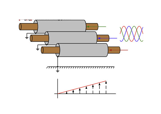
The EHV series of cable accessories now offered by suppliers such as Pfisterer completes the range up to 550 kV cables. This includes a dry, pluggable cable connection for transformers and gas insulated substations, cable terminations, cable joints and pluggable cable joints as well as a blind dummy plug. These components are type tested and can be used for all kinds of XLPE cables, independent of core diameter, diameter over insulation and manufacturer. All field control units and electrical stress materials are pre-fabricated and routine-tested, thereby ensuring high operational safety. For example, the dry pluggable system can handle cable diameters of 3000 mm² CU or AL conductor, carrying up to 4000A nominal current. Maximum diameter over insulation is 144 mm. Fig. 1 depicts the principal set-up. An additional benefit comes from the housing, which is completely touch-proof and waterproof. It is also salt-water resistant meaning it can be used in coastal areas as well as in offshore surroundings.
Cable Joints
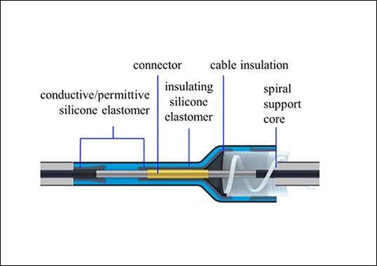
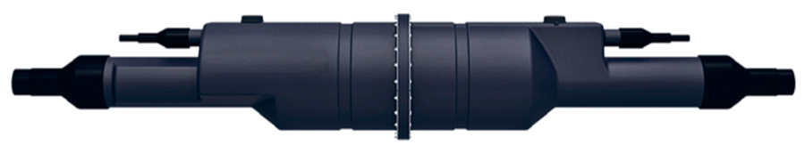
The technology behind joints such as Ixosil has been extensively tested ensures simple installation of the waterproof, external housing along with maximum operational safety. Using a patented bolted connector allows the conductor to be connected with optimal contact force and without need for special tools. Moreover, treatment of cable shielding can be individually adapted by cable type or based on customer needs. Fig. 2 shows a typical possible arrangement.
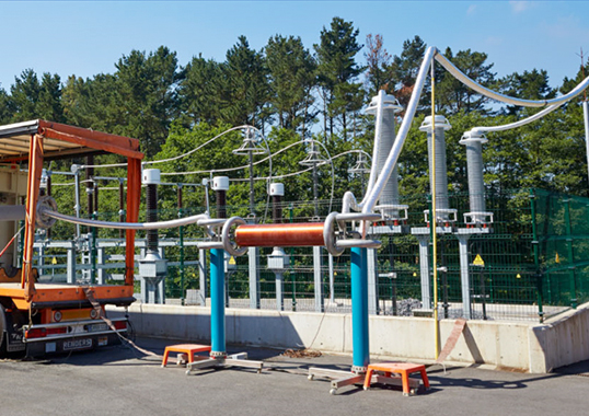
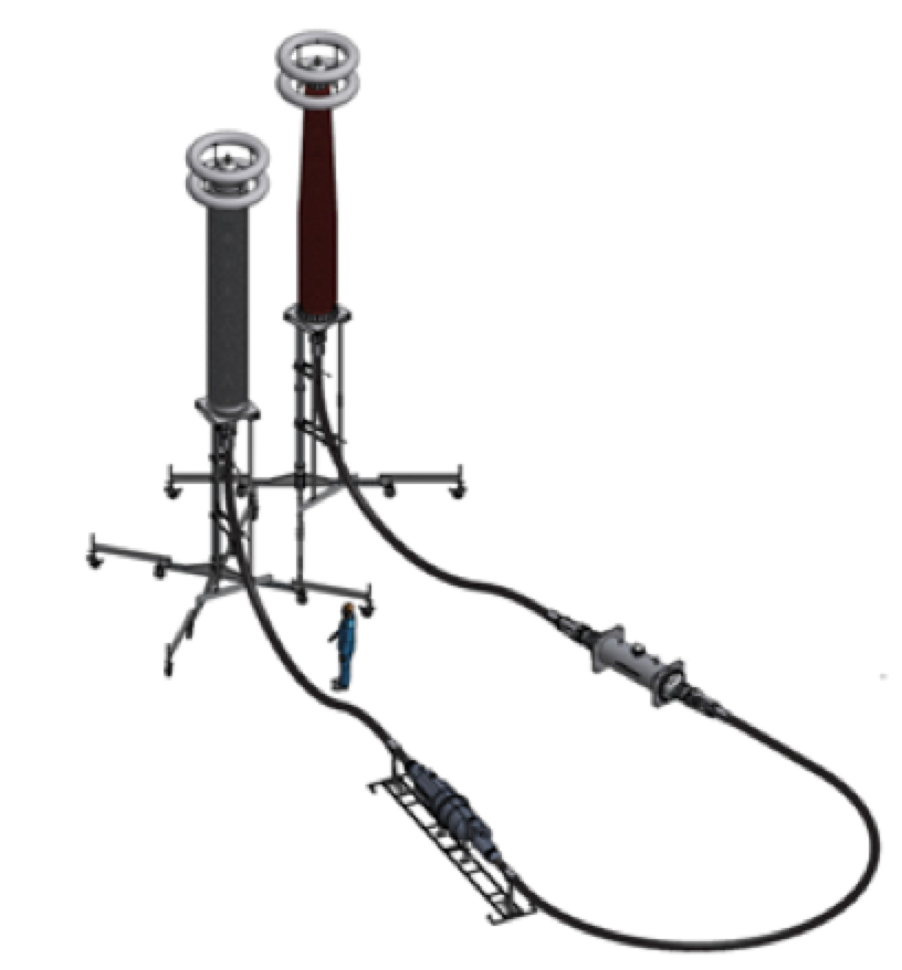
One qualification requirement is performing a Type and a Prequalification test according to IEC. Fig. 3 shows a sample set-up for a type test according to IEC 62067.
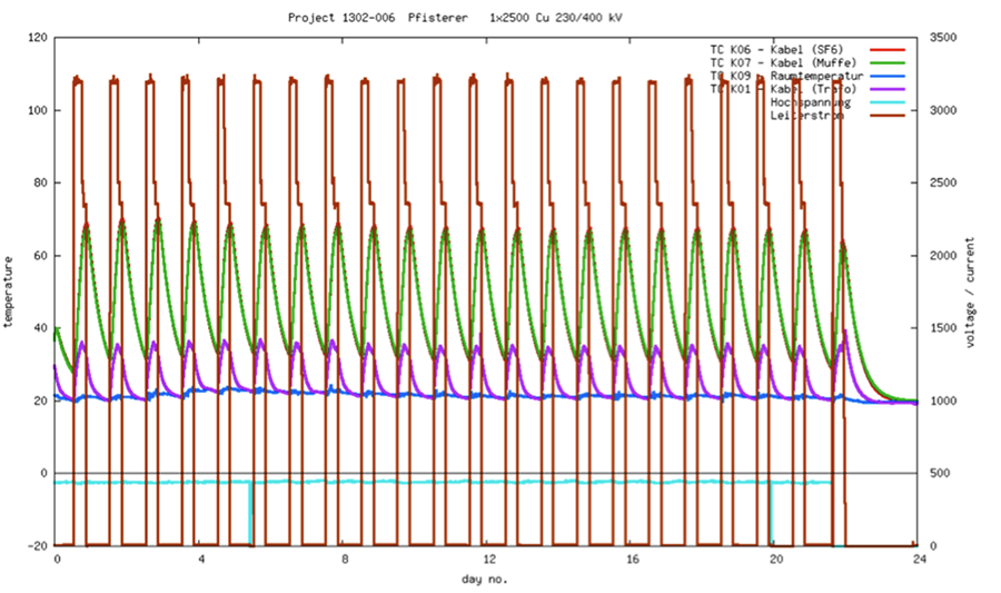
A major hurdle is the so-called Annex G test whereby the joint is submersed in water at 1 bar pressure and cycled, with number of cycles depending on regional specifications. Chart 1 1 shows heat cycle measurements from such a test, with temperature at a so-called ‘dummy’ used for calibration.

Outdoor Cable Terminations
Another vital component in cable networks is the outdoor cable termination, which offers a water-repellant outer surface made of silicone. Minimum creepage distance is 16,600 mm which covers the high pollution class of >65mm/kV. The stress cone of the cable termination is also pre-molded and routine tested, which allows fast mounting and assures high reliability of the main parts. A special centering device, unique in this family of terminations, ensures the right position of the stress cone, in radial orientation, as well as axial centricity of the electrically most important element.
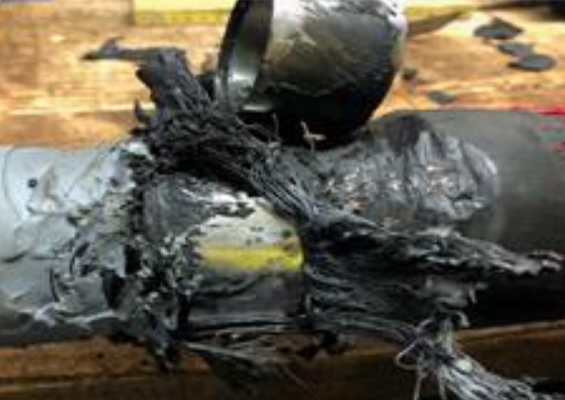
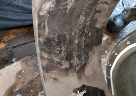
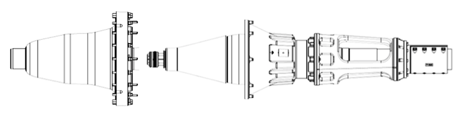
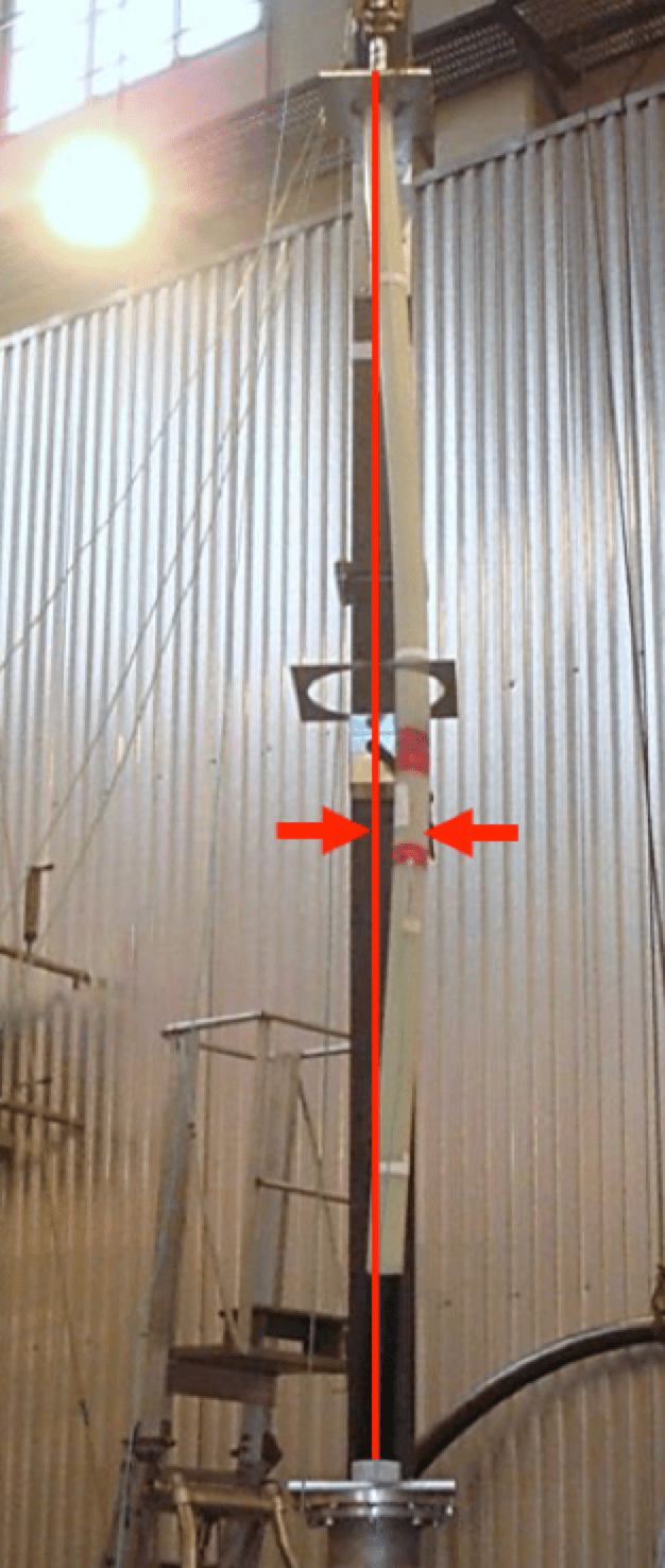
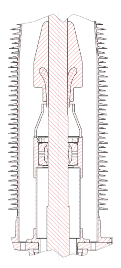
A major hurdle facing outdoor terminations is overall size, often resulting in a considerable length of free cable inside the termination. Due to load change, conductor length changes as well. At high temperatures, this leads to elongation and therefore a buckling effect. The smaller the conductor the higher the buckling effect. Tests were therefore conducted at a cable with 300 mm² copper conductor and a corresponding diameter over insulation of 62 mm (refer to Fig. 4). Maximum buckling of this arrangement was shown to be outside the limiting values.
To prevent a buckling effect of the cable inside the insulator of the cable termination, a special spring device has been integrated in the termination (see Fig. 5). This allows length compensation of the conductor inside the termination. At the same time it prevents the conductor from becoming off-center and therefore ensures constant field distribution, independent of temperature changes.
to load results in buckling effect.
Like all other Pfisterer cable terminations, the base plate is insulated from the cable screen, which allows for a flexible earthing system, according to customer requirements. To allow quick and safe cable connection without need for special tools, both the top bolt of the termination and the connection in the joint are equipped with a patented Sicon bolted connection. This offers a life-long contact force and assures the connection to the cable connector.
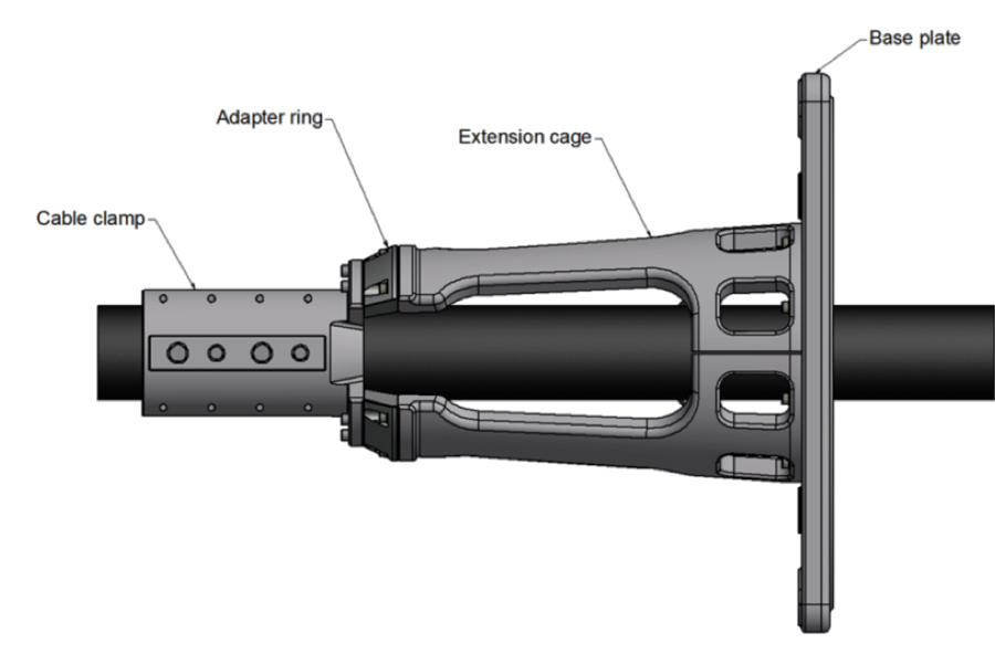
A new cable clamping system has been developed for both cable connector and cable termination. As shown in Fig. 6, this consists of basically two parts – an extension cage and a cable clamp. If the system is to be used on very small outer cable diameters, an additional adapter is available to use the same system. The cable clamp is adjusted on the cable diameter to allow maximum retention force, ensuring minimal pressure on the cable. Even great cable weights can be handled. At the same time, this system fulfills a centering function to ensure proper positioning of the cable in the respective termination.

Decrease in Skin factor
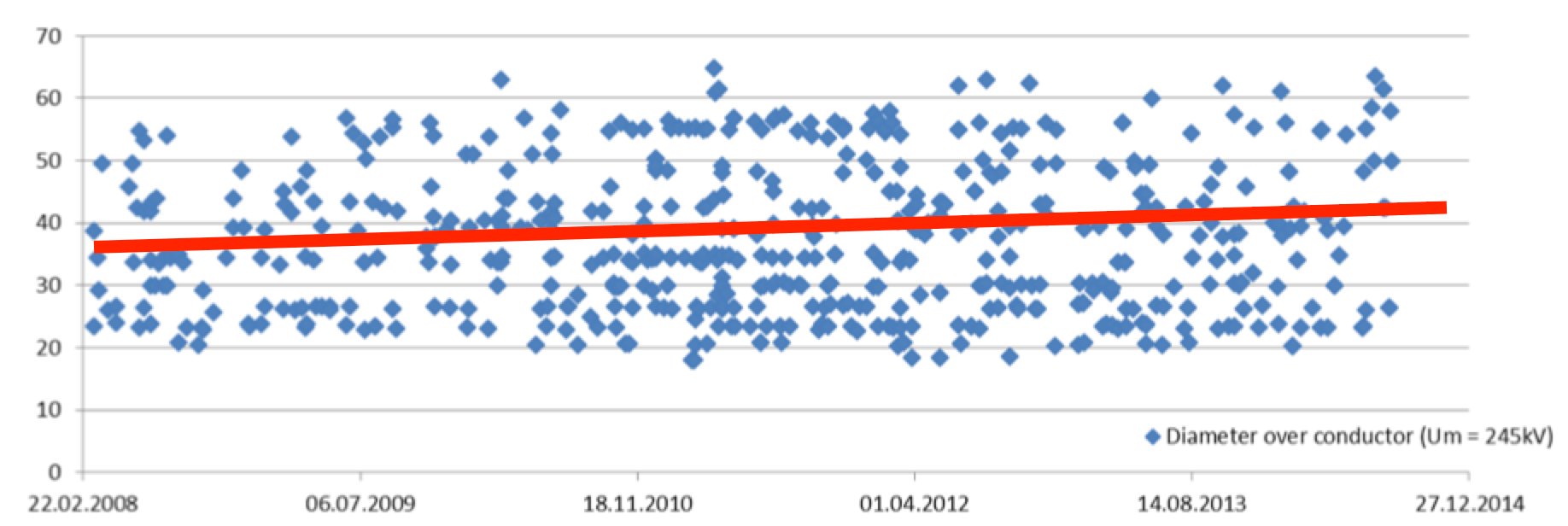
Decentralized energy production, driven mainly by increased generation of renewables, requires additional network capacity for energy transfer and distribution. At the same time, growing urbanization is requiring additional distribution capacity. This trend is demonstrated by evolution of cable dimensions, as in Chart 2 which tracks global use of cable connectors for UM = 245 kV. Since 2006, cables diameters have increased by approximately 10%.
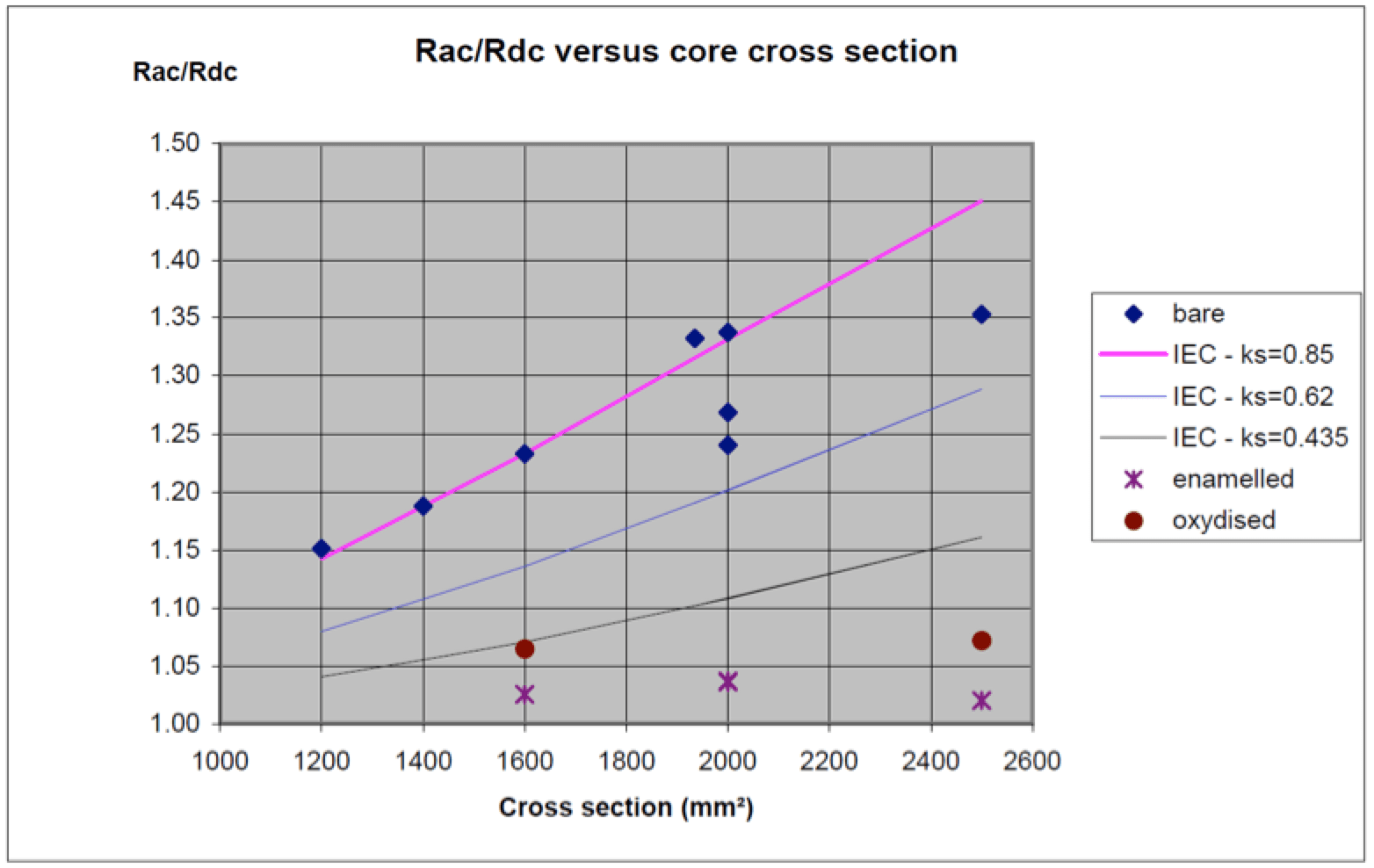
While increasing conductor cross-section is an option, due to the ‘skin effect’, the benefit is not equivalent to the investment cost. Chart 3 compares use of different conductor types and shows resistance increase in relation to the skin effect. As can be seen, the ratio of AC resistance to DC resistance is close to equivalent utilizing enameled conductors, which are stranded conductors with every single wire insulated. No current flow between single strands results in a tremendous reduction in skin effect.
This is a major advantage but challenges the design and functionality of cable accessories. For example, the contact surface requires homogeneous current distribution. In the past, solutions required removal of insulation layers by abrasives or heat – processes that are time consuming and dependent on quality of workmanship. Moreover, additional cable length is required due to bending of the strands, which runs against the goal of compact solutions. Latest developments in this area use the front surface of the cable conductor as a connecting surface. Contact surface is offered with a non-compressible yet flexible material. This solution is being used for joints, terminations and pluggable systems and components for such trial installations have been delivered over recent years.

Flexibility
Increase in transmission capacity is a vital enabler of tomorrow’s power grids while network flexibility is another key requirement. Pluggable systems are becoming more popular but an enclosed system, such as a cable system, needs thought in regard to protection.
Surge Protection
Surge arresters are usually either SF6-insulated or air-insulated, with both facing challenges. Use of SF6 is becoming more restricted and testing requires SF6 gas handling. On the other hand, air-insulation requires creepage and space. In addition, positioning is not optimal since substation layout usually does not allow an air-insulated arrester to be positioned as close as possible to the transformer when cables are being used.
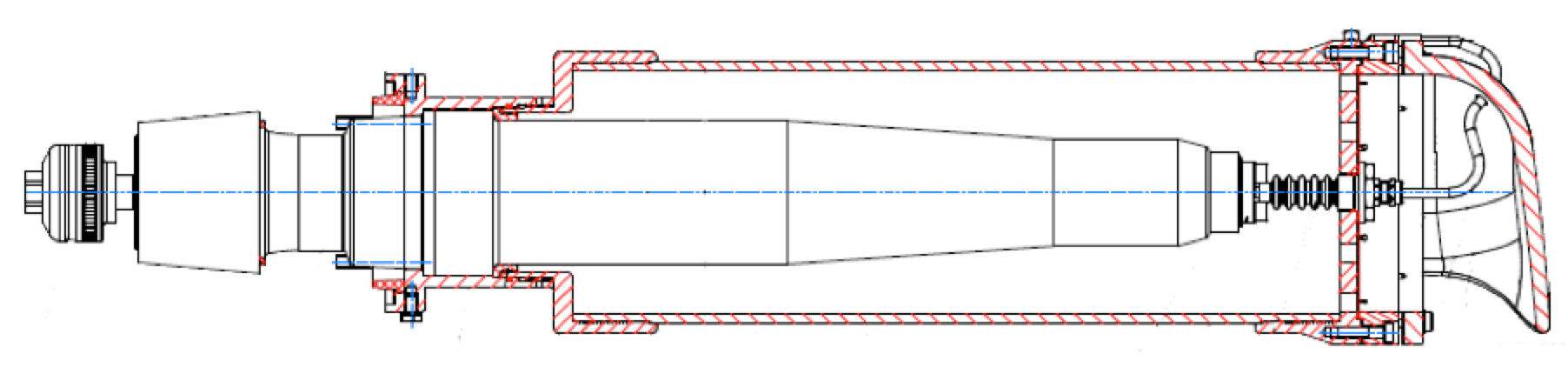
A pluggable solid-insulated arrester has been developed and tested up to Uc = 144 kV (Ur = 180 kV) in reference to the latest standards. The arrester’s main insulation is solid and there is no insulation, liquid or gas such as SF6. Fig. 7 shows a cutaway of such an arrester. The main portion in regard to arrester function is the metal oxide resistor blocks that are used as a non-linear component with very low leakage current during operation. These blocks are connected to the male part of the plug-in system and insulated by a silicone body that includes field control elements. The head fitting includes a bursting disk for pressure relief as well as a turnable head to redirect gas in the event of failure, as per IEC 60099-4. The housing is made of glass-fiber reinforced resin and allows high mechanical strength as well as protection of the silicone body against the environment. The silicone body itself is protected and touch-proof. A special arrangement of the earthing path allows connection of monitoring devices or discharge counters if desired.
Pluggable Bushings
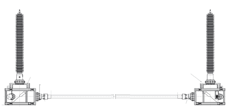
Conventional bushings are used mainly on transformers and there is widespread application of resin impregnated paper types. During assembly of such a conventional bushing, the transformer tank has to be opened and its main insulation, typically mineral oil, is exposed to the environment. This process can cause difficulties in terms of pollution, humidity and required assembly time. In a pluggable system, the transformer is enclosed by a socket, which offers an interface that also allows all options without oil and without need to open the transformer tank. Such a system can be tested using testing equipment, voltage proof enclosed and connected to a cable system using cable connectors or to an overhead line utilizing pluggable bushings. These pluggable bushings are already available up to UM 245 kV with solutions for higher voltages also underway. While pluggable bushings currently offer their main advantages in respect to transformers, other applications are also becoming possible using this same approach. These include short or medium-term applications when downtime is crucial and full flexibility required. All components are pre-tested and shipped to site such that final assembly becomes a simple plugging process. Fig. 8 depicts such a temporary arrangement at UM 245 kV.

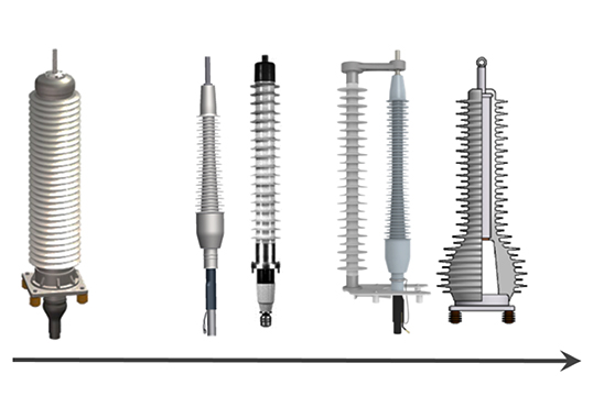
Evolution of Cable Terminations
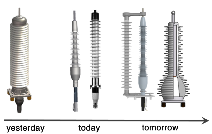
The majority of cable terminations these days are still oil-insulated and consist of a composite housing as well as a silicone stress cone for field control. While the technology is well established, when considering assembly, long-term stability and failure mode, this arrangement no longer always complies with customer expectations. For example, many cable terminations up to UM 170 kV have now become dry using solid insulation. Not only is the assembly process easier but no liquid insulation means optimal failure mode. The next evolutionary step is dry type terminations that are self-supporting, enabling integration of additional functions (see Fig. 9). Self-supporting systems and pluggable solutions are already available and tested up to UM 170 kV with higher voltages in process.
Conclusions
Networks are changing. Higher voltage levels and need for increased power transmission require new solutions. Flexibility and modular set-up are key elements when it comes to cable accessories. At the same time, liquid and gas insulation is being minimized and, where possible, replaced by solid alternatives. Additional integrated functionality is also underway. Cable accessory technologies are adapting to these needs and changing faster than ever.