Global deployment of RTV silicone-coated insulators has grown rapidly, driven by the need for enhanced pollution performance in harsh service environments.
This edited contribution to INMR by Yasushi Okawa and Motohiro Maeda of NGK Insulators in Japan presents a methodology for evaluating coated insulators based on extensive field experience and laboratory testing. The aim is to optimize technical specifications beyond what is described in CIGRE TB 837 and IEC TS 63432 (in process). Limitations to the existing 2000h accelerated ageing test are also discussed and improvements proposed based on field experience in severe environments, including deserts and industrial areas with high non-soluble deposit density.

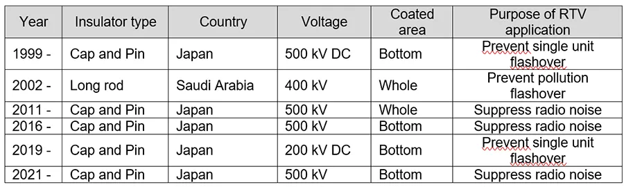
Table 1 summarizes selected field applications of RTV coated insulators since 1999 where no issues were reported by users.
Findings from this field experience, combined with laboratory testing and published papers on the topic, can be summarized as follows:
1. RTV coated insulators enhance pollution performance, reduce visible corona discharge caused by pollution, and mitigate associated noise.
2. There is a record of use covering up to 25 years. Signs of deterioration in coatings have been observed.
3. Resistance to arcing and partial discharge varies depending on specific RTV material.
4. Degradation rate of RTV coated insulators can differ, depending on whether the dielectric substrate is porcelain or glass.
5. Performance of RTV coatings is influenced by factors including coated area, adhesion condition and uniformity of coating thickness.
6. RTV coating is more sensitive to jet washing than are polymeric insulators.
Data accumulation and investigation of factors and mechanisms governing performance are still ongoing. But it can be stated that high quality RTV coated insulators can be achieved by selecting the appropriate material as well as application process.
Specification of RTV Coated Insulators Based on Practical Application
The technical specification of RTV coated insulators is still under review by IEC PT 63432. Table 2 shows the draft specification.
It is known that controlling coating thickness is essential since tracking performance will vary depending on coating thickness. CIGRE Technical Brochure 837, for example, suggests that increased coating thickness can lead to reduced durability against tracking (see Fig. 1).
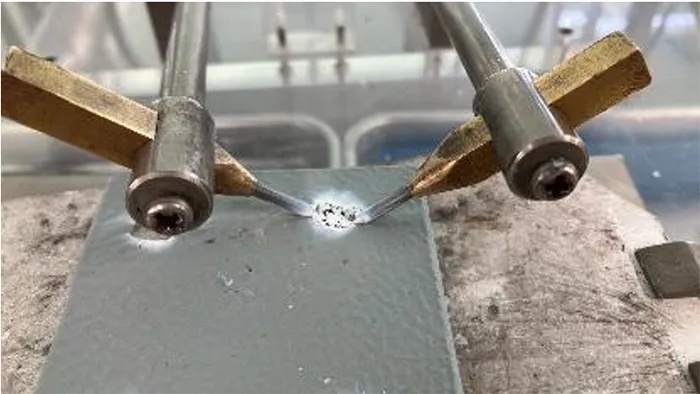
In this research, the relationship between RTV coating thickness and tracking resistance was investigated using the Dry Arc Resistance Test, in accordance with ASTM D495. Results indicate a similar trend (see Figs. 2 & 3). Therefore, controlling coating thickness within an optimal range is important to maintain sufficient arcing resistance.
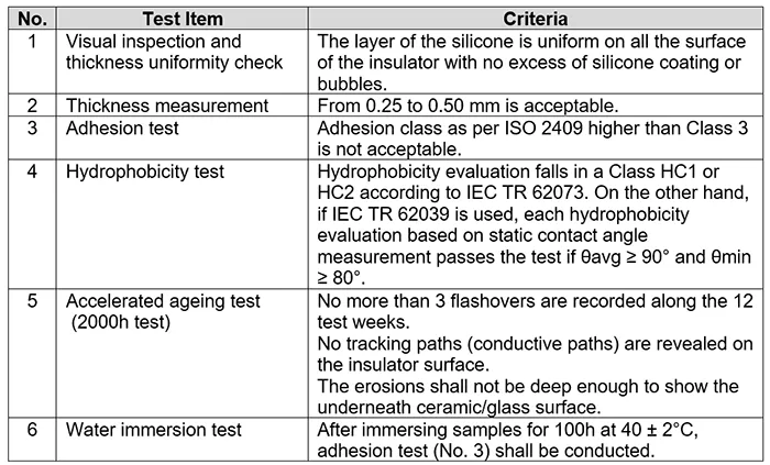
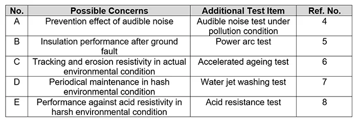
To ensure reliable products, supplementary specifications have been established based not only on the draft of IEC TS 63432 but also on field experience. Table 3 shows the additional specifications recommended. Specific test procedures and criteria are described in References 4 to 8.
Audible Noise Test Under Pollution
This test is intended to evaluate the audible noise generated by partial discharges under polluted and wetted conditions. The test procedure consists of three steps simulating field conditions. The first is pre-conditioning the RTV silicone surface by spraying dense Tonoko slurry and washing it off. The second step is artificially polluting insulators by applying a salt suspension directly to them. The third step is energization and fog injection to evaluate audible noise level.
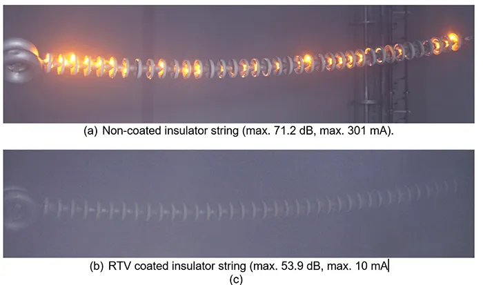
Examples of test results simulating actual 500 kV overhead lines near coastal areas are presented below. Test conditions are summarized, and the corresponding results shown in Fig. 4. It was confirmed that application of RTV coated insulators reduced audible noise by more than 10 dB.
Specimens: 320 mm cap & pin insulators with bottom RTV coating
(corresponding to U 300 B of IEC 60305: 2021)
Test Arrangement: Single tension string of 38 insulator units (horizontal)
Degree of Pollution: SDD=0.5 mg/cm2 (corresponding to the class Heavy of IEC 60815-1)
Applied voltage: 303 kV (maximum phase to ground voltage of 500 kV)
Field tests on an energized 500 kV transmission line located about 480m from the seacoast (designed ESDD of 0.5 mg/cm2) confirmed that an RTV coating reduces corona discharge compared to uncoated insulators (see Fig. 5).
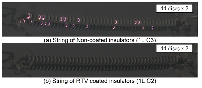
(Average temperature: 28.3℃, average humidity: 88%).

Power Arc Test
RTV coated insulators must be able to maintain their insulation characteristics even after ground faults caused by flashovers due to lightning surge, switching surge or pollution. To verify the capability of reclosing overhead lines equipped with RTV coated insulators, it is proposed to carry out the wet power-frequency withstand voltage test after the power arc test.
The test consists of 2 steps: the first simulates RTV coated insulators exposed to ground fault current and the second simulates reclosing after ground fault current. Details of test conditions are as follows.
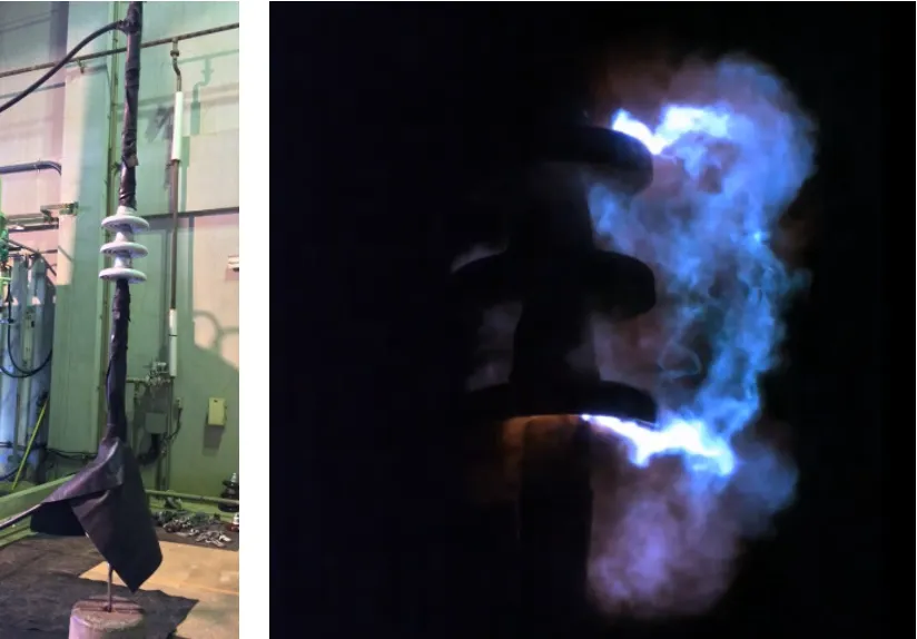
Step 1: This test is referred to as the power arc test in IEC 61467: 2008 section 8 test on short string. Test condition is 12,000A x 0.1 second x 2. In the case of fully coated cap & pin type insulators, to expose the arc jet to both top and bottom sides, the test specimen was installed at the top of the string during the 1st shot and at the bottom of the string during the 2nd shot. The criterion is that no insulator separation occurs. The test set-up is shown in Fig. 6.
Step 2: This test is referred to as the wet power-frequency withstand test in IEC 60383-1: 1993. In the case of sample of U160BS in IEC 60305: 2021, test voltage was set at 40 kV and maintained for 1 min. The pass criterion is that no flashover occurs. The test set-up is shown in Fig. 7.
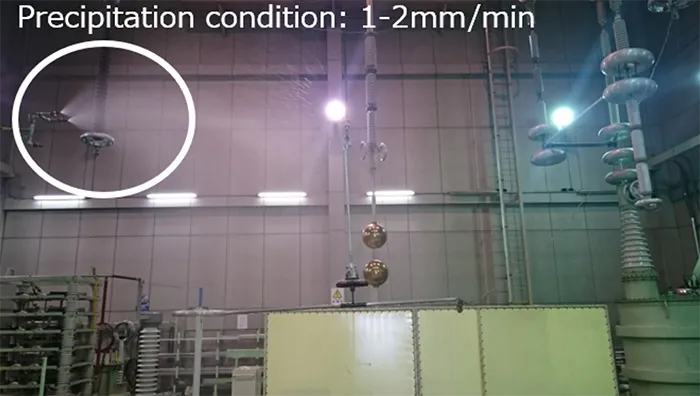
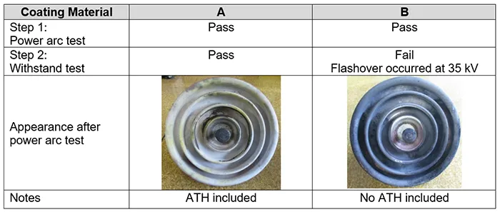
Table 4 shows results of these tests where two coating materials were evaluated. It was found that insulation characteristics after exposure to power arcS were dependent on ATH content.

Accelerated Ageing
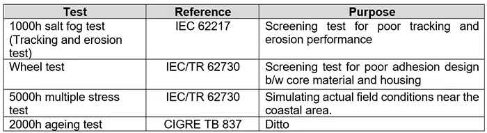
It has been proposed that accelerated ageing testing for RTV coated insulators should be based on the same test methods used for polymeric insulators. Table 5 summarizes accelerated tests. Among these, the 2000h ageing test has established a proven track record in places such as Italy since it accurately reproduces the deterioration observed in coastal environments.
The objective of accelerated ageing testing is to evaluate degradation of silicone rubber – specifically reduction in pollution withstand voltage resulting from erosion, tracking and loss of hydrophobicity recovery. However, there is still room for improvement in some aspects of the 2000h ageing test method to achieve this objective. Enhancing the test procedure to better simulate actual environmental conditions will lead to greater accuracy in predicting service life.
The following describes issues and countermeasures with regards to the current 2000h ageing test.
Issue 1: Long Evaluation Time
Requiring approximately three consecutive months of testing to evaluate a single condition is clearly inefficient. Therefore, test stresses should be concentrated on those factors that directly contribute to degradation of the material. Primary degradation mechanisms are linked to electrical discharges during energization, salt fog and wetting processes that significantly accelerate rubber deterioration. By contrast, UV and rain processes can be excluded from the test sequence. To evaluate UV resistance, ISO 4892-1 “Plastics – Methods of exposure to laboratory light sources” is considered more appropriate. Exposure to rain may in fact slow the degradation process due to washing away of pollutants.
Issue 2: Simulation of More Severe Environments
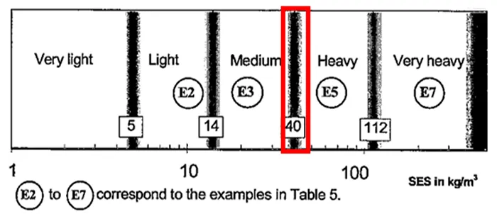
Salt fog concentration is fixed at 40 kg/m³, which does not necessarily reflect the actual application environment (see Fig. 8). According to the pollution severity classifications outlined in IEC TS 60815-1, it is possible to more accurately simulate actual degradation by adjusting salinity concentration to match levels found in the installed environment.
Issue 3: Simulation of High NSDD Environments
In many cases, pollution design is carried out by ESDD and NSDD instead of SES (Site Equivalent Salinity). Accordingly, it is also important to evaluate performance under conditions of high NSDD, such as in desert and industrial environments.
The current 2000h ageing test, however, only simulates coastal environments without considering NSDD value. One approach proposed to reproduce such conditions involves applying pollution prior to testing to achieve the required pollution level. In other words, the procedure sees pollution applied to insulators with specified ESDD and NSDD values, drying it, and finally humidifying the test chamber to generate continuous discharges. This is as per the solid layer method described in IEC 60507 which specifies artificial pollution tests.
Currently, research is underway to establish appropriate humidity settings and pollution update frequencies. This method will enable more accurate reproduction of deterioration and life expectancy evaluation – even in areas where pollution levels are designated by ESDD and NSDD.

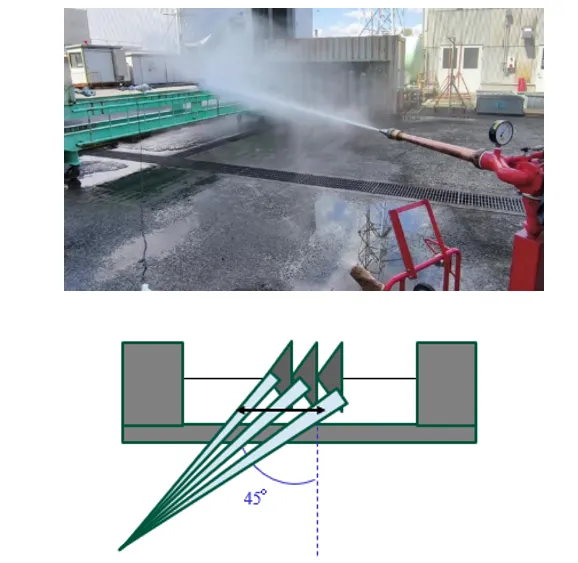
Water Jet Washing Test
Polymeric insulators in heavily polluted areas of the Middle East are regularly subjected to jet washing. Although some utilities have formalized jet washing tests in their specifications, test conditions and criteria often remain undefined.
Since stringent cleaning could damage RTV coatings, it is essential to establish appropriate testing conditions that reflect actual live-line washing practices. Jet washing tests were conducted using RTV coated insulators (whole surface) under laboratory conditions. Tables 6 & 7 present the results obtained.
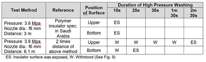
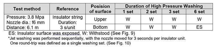
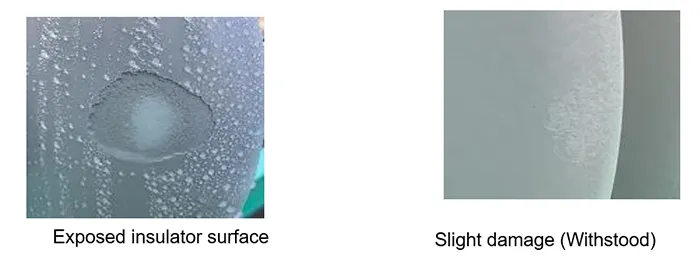
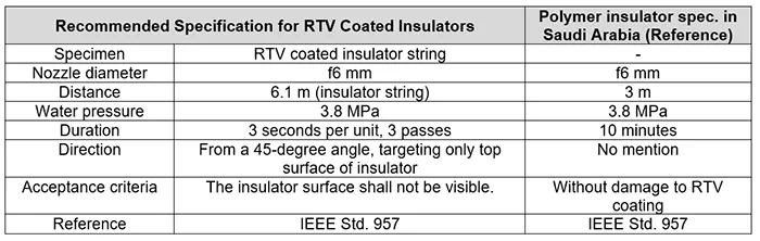
Based on the above, it was found that lengthy water jet washing on individual insulators in accordance with specifications for polymeric insulators damages the RTV material over only a short period. Therefore, if jet washing is required, it is necessary to establish appropriate test conditions. These should reflect actual live-line washing practices, with reference to IEEE Std. 957 ”IEEE Guide for Cleaning Insulators” for parameters such as nozzle-to-insulator distance and water pressure. Instead of testing individual insulator units, verification should ideally be conducted using insulator strings to better simulate actual conditions. The following test method is proposed, which reflects actual field practice. Table 8 provides recommended specifications for RTV coated insulators.
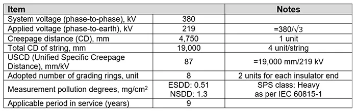
Acid Resistance Test: Field Observations Under Heavily Polluted & Wetted Conditions
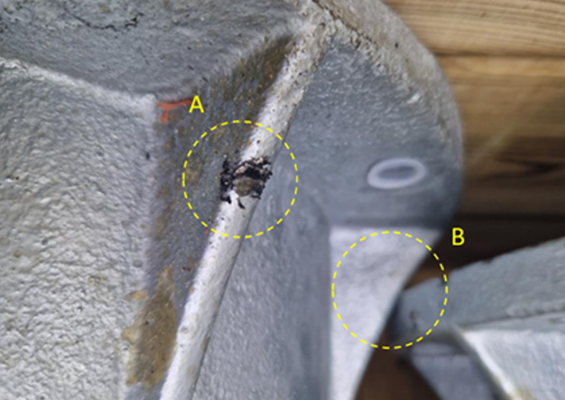
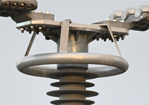
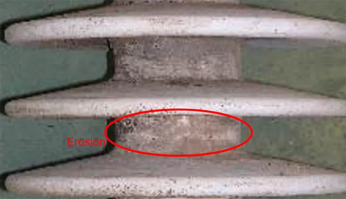
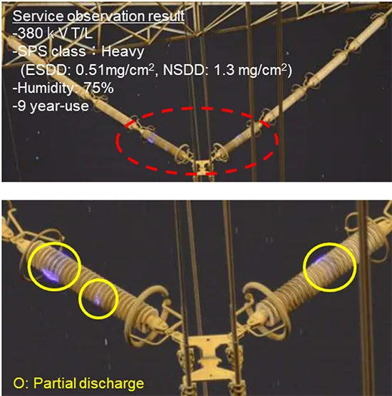
Field experience has reported severe deterioration of RTV coated insulators under heavy pollution. Table 9 shows the application condition and specimen insulator. For example, erosion and loss of hydrophobicity could be observed on the housing of the trunk of coated insulators removed from a transmission line.
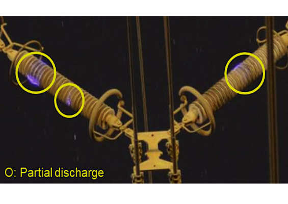
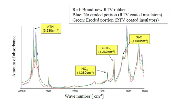
Fig. 11 shows an example of their surface condition and Fig. 12 offers a view of partial discharge activity observed during nighttime and under high humidity. It is noteworthy that nitric acid appeared on the deteriorated portion. Fig. 13 indicates the FT-IR spectrum of the eroded RTV coating material.

Proposed Acid Resistance Test
Field experience indicates that nitric acid is generated by partial discharges under heavy pollution and wetted conditions. Resistance to acid attack is therefore an important property for rubber materials used outdoors. To evaluate performance against nitric acid, a new evaluation method is proposed – a nitric acid immersion test. Currently IEC TR 62039 (Selection Guidelines for Polymeric Materials) introduces such a test in Annex A and details of the test method is still under consideration within CIGRE WG D1.62. It is recommended that the nitric acid immersion test be applied to identify high quality RTV silicone materials having the required acid resistance.
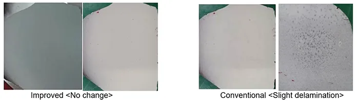
The test condition is 1 mol/L nitric acid solution and immersion for 500h, (as in Fig. 14). Fig. 15 shows a typical test result. Up to now, no significant defects in insulators coated with improved acid resistant RTV material have been reported, even under heavy pollution. The reason for selecting level of acidity, the pH of some water drops in the artificial test, (so called “small-scale weathershed corona ageing test”) was zero. This is equivalent to 1 mol/L. (Reference: ISEIM 2020, SS-8 “New Accelerated Ageing Test for Polymer Insulators”).
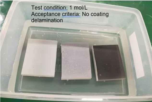
(Left: Improved, Center: Conventional, Right: Non-coated).
Conclusions
Findings from years of field experience and testing of RTV coated insulators demonstrate the importance of supplementing existing specifications with additional evaluation methods. These include audible noise testing, a power arc withstand test, an accelerated ageing test, a water jet washing test, and an acid resistance test.
These tests help to address real-world challenges faced in harsh service environments, such as desert regions and industrial zones with high levels of NSDD, and where conventional testing may not be sufficient.
Improvements to the 2000h accelerated ageing test have been proposed to better simulate actual degradation mechanisms, such as inclusion of UV and rain processes as well as adjustment to salt fog concentration. Introduction of a nitric acid immersion test further enhances the ability to evaluate material durability under severe pollution and partial discharge conditions.
Integrating all these practical insights into specifications will contribute to application of only high quality RTV coated insulators offering enhanced reliability and service life. Future standardization efforts should consider the above findings to ensure that RTV coatings continue to meet the evolving demands of global power transmission systems.
BIBLIOGRAPHY
[1] CIGRE TB 837 “Coating for improvement of electrical performance of outdoor insulators under pollution conditions”, (June 2021)
[2] Noriyuki TAKADA, Yoshiaki AOKI, Kuniaki KONDO, Atsushi ITO “Prevention effects of single unit flashover with insulator strings in HVDC lines”, (CIGRE 2023 Sendai Colloquim, Japan, October 2023, B2 PS1, Paper No.5302827)
[3] Raouf ZNAIDI, Ahmad Al-THAGAFI, Abdullah BOUCHTI, Kalid Al-SOUFI “Assessment of Operating Life of Silicone Rubber HV Insulator Coatings in Harsh Desert Environment”, (CIGRE 2024 Paris Session, B2 PS2, Paper No.11471)
[4] Ryo Yuzawa, Asuka Tokuriki, Motohiro Maeda, Toshiyuki Nakachi “Field Experience and Maintenance Assessment of RTV Coated Cap and Pin Insulators in Japan”, (CIGRE 2024 Paris Session, B2 PS2, Paper No.10981)
[5] Mina Takagi, Hiroki Sakai, Motohiro Maeda, Kuniaki Kondo “The suppressing effect of corona discharge with RTV silicone rubber coated insulators under polluted conditions”, (CIGRE – AORC Technical meeting 2020, Kanazawa, Japan, April 2020, Paper No.C000064)
[6] Motohiro Maeda, Tomoya Iizuka1, Ryuuji Yamada, Asuka Tokuriki “Evaluation of Crona Pprevention Performance of Damaged RTV Coated Insulators to Develop on-site Repair Guidelines”, (23th International Symposium on High Voltage Engineering, Glasgow, UK, August 2023, Paper No. P2.12)
[7] IEC 61467: “Insulators for overhead lines-Insulator strings and sets for lines with a nominal voltage above 1000V ‐AC Power arc tests”, (2008)
[8] IEC 60383-1: “Insulators for overhrad lines with a nominal voltage above 1000 V Part1”, (2023)
[9] IEC 62217: “Polymeric HV insulators for indoor and outdoor use – General definitions, test methods and acceptance criteria.”, (2012)
[10] IEC/TR 62730: “HV polymeric insulators for indoor and outdoor use tracking and erosion testing by wheel test and 5000 h test”, (2012)
[11] IEC 60815-1: “Selection and dimensioning of high-voltage insulators intended for use in polluted conditions – Part 1: Definitions, information and general principles”, (2008)
[12] IEC 60507: “Artificial pollution tests on high-voltage ceramic and glass insulators to be used on a.c. systems”, (2013)
[13] IEEE Standard 957: “IEEE Guide for Cleaning Insulators”, (2005)