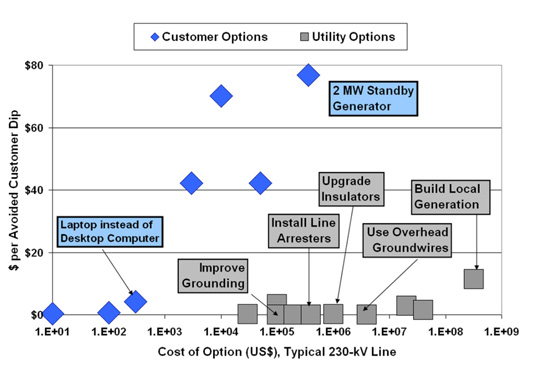
Despite a range of remedial measures, lightning remains one of the leading causes of line tripping disturbances. Therefore, solutions to lessen its impact remain a priority for line designers and power system operators across the globe. Installation of transmission line arresters along the route is regarded as the one of the most economical and one of the simplest strategies to deal with lightning disturbances. Alternatives such as reducing tower footing resistance are typically far more expensive, especially in mountainous areas. So is the option of replacing an overhead line with underground cable.
This edited past contribution by arrester experts at TE Connectivity discussed essential system parameters that allow for successful installation of line surge arresters. The end goal of such a process is optimizing selection of a non-gapped line arrester and coordinating it with the disconnector to mitigate problems of line tripping due to lightning.
Data Gathering
To be in a position to optimize installation of line surge arresters, certain important data need to be collected beforehand. These include:
1. Information on Towers
• height & configuration of cross-arms;
• location & length of phase insulators;
• maximum phase conductor movements during maximum wind speed design;
• location of mechanical dampers;
• tower footing impulse resistance along line;
• location of shield wire(s), if any.
2. Information on Line Insulators
• CFO/BIL
3. System Parameters
• reclosing times & scheme;
• short-circuit current;
• data on substation arresters;
• decisive TOV requirements;
• targeted reduction in trippings/yr for the system;
• maximum switching voltage along the line for switching protection
4. Environmental Data
• ground flash density and/or number of thunder days/yr
Once all this information has been assembled, selection of a line surge arrester (LSA) can start with a system study to identify possible solutions using available programs such as EMTP, Sigma, etc.

Applications for LSAs
There are basically four main applications of an LSA. The most common is reducing tripping either from lightning hitting the tower or shield wire and causing back flashover or from direct lightning strike to a phase conductor causing a flashover from line insulator to tower. This application will also prevent flashovers due to induced overvoltages from lightning hitting tall nearby structures such as trees or wind turbines.
For this application both non-gapped line arresters (NGLAs) and externally gapped line arresters (EGLAs) can be used. If the target were to have no flashovers, no matter how these might originate, an LSA would have to be installed on every tower and on all phases of a line. This, however, is usually not cost-effective except in cases where the consequences of line tripping are especially harmful to the system or its customers. One such example might be double EHV circuits coming from a generation plant where any double circuit tripping could result in a major blackout. Rather, in most cases the number of LSAs as well as on how many phases these are installed will depend on tower footing resistance as well as the outage reduction target. Moreover, charge requirements will depend greatly on whether shield wires are used or not since risk of high direct strike charges increases in the latter case.
Another area of application of NGLAs is using them in place of reclosing resistors to control switching voltages along an EHV line. This application requires an NGLA be installed on all three phases but only on a few selected towers – typically in the middle for shorter lines or at points one-third and two-thirds along the overall length for longer lines. Here, the NGLA can be used either separately or in combination with other systems such as controlled switching. The goal is always no tripping due to switching. Typically, the energy/charge requirement for such NGLAs is one class lower than for substation arresters since they cover only half or a third of the line.
A third major application is when upgrading system voltage while keeping the same structures and line insulators, which typically requires NGLAs to be installed on all towers and phases. While costly, it may still prove the most economic solution given that use is made of an existing line corridor. In this application, the NGLA will protect against both lightning and switching surges. NGLAs can also be used whenever new compact lines are designed e.g. where there is limited right-of-way. Depending on design, sometimes only the top phase will require them. The target value would likely be the same as for other lines in the same area equipped with ‘standard’ insulation. Energy/charge requirements would come from the necessary system studies.
A fourth application area for NGLAs sees them installed on one to three of the towers closest to the entrance of GIS substations, which are very sensitive to overvoltages with high steepness. GIS arresters are typically more costly than NGLAs, which could be installed more economically. NGLAs would limit incoming overvoltage amplitudes as well as reduce steepness by preventing flashovers on these towers. Given such an installation, internal GIS arresters would no longer be needed. In this type of application all phases would have to be protected on the selected towers and it would be preferable to select NGLAs with very low residual voltages on the last tower in order to increase protective distance inside the GIS. Even parallel columns could be advantageous. Since the NGLA installations on other towers would just be to reduce incoming steepness, they would only need standard design.
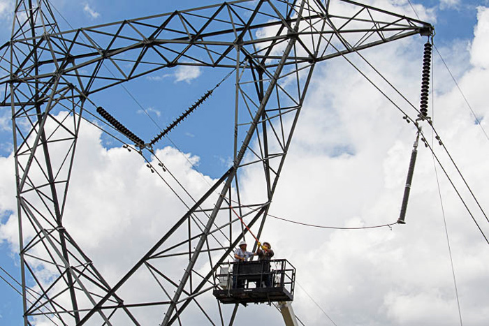
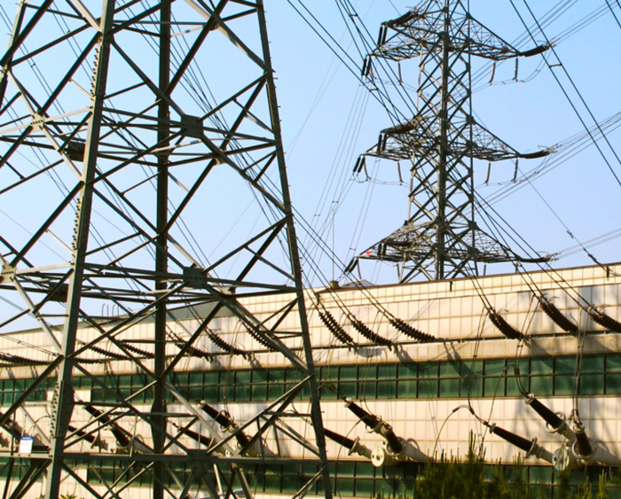
Apart from these main applications, there is a possible fifth – although not for permanent installation. During live line work, NGLAs could be hung at both ends to prevent flashover of line insulators on towers being worked on. Such NGLAs would not typically need grading rings for system voltages up to 245 kV and then only reduced sized rings for 420 kV and above given that they experience COV for only limited time.

System Aspects
Reliability of power lines these days is measured in total outage time, including maintenance and line tripping. That means that if there is a flashover across a line insulator on a transmission or distribution line it is desirable for the power utility to restore service as quickly as possible. For this purpose, a variety of fast reclosing schemes are used. A requirement in this regard is that any LSAs installed will not influence these schemes, even if the LSA is overloaded due to excessive lightning discharge. It is also required that an LSA, once disconnected, is not allowed to leave the conductor or tower with lower insulation withstand level because it is short-circuited.
The mitigation against such a situation is to install disconnectors both for NGLAs and EGLAs. Performance must match the system’s fast reclosing scheme so that disconnector separation is complete before reclosing occurs. The available time for the disconnector to operate is therefore relay detection time of the earth fault plus breaker opening time, to which must be added reclosing time interval plus breaker closing time. This total time is then the ‘window’ during which successful separation must take place. However, disconnection time also depends on actual short-circuit current of the system. LSA installations located far from generation plants may have actual short-circuit currents significantly lower than if close by, even for a directly earthed system.
Disconnector Characteristics
A disconnector serves a dual purpose: first to facilitate fast reclosing and second to visually identify which arrester has been overloaded and needs to be replaced. A TLA disconnect device is required to operate when the arrester is overloaded and detects a current flowing for a long period of time until full system short-circuit is present. At the same time, it is a simple device that must work in series with the arrester when dealing with lightning or switching surge events. Type tests are carried out to verify that a disconnect device is capable of surviving the relevant temporary overvoltage as well as lighting and switching charges of the LSA without failing prematurely. Typical disconnect characteristics showing opening time versus power frequency current are shown in Fig. 1.
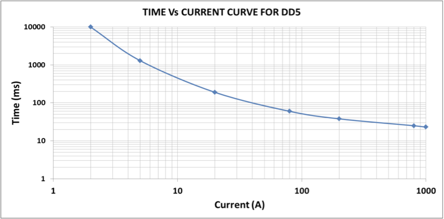
The lower the short circuit current, the longer opening time is needed for the disconnector. As such, it may be more critical for non-directly earthed systems to facilitate fast reclosing versus directly earthed systems, if the disconnector is not fast enough. Another important criterion is that, once triggered to operate, the disconnector never be allowed to stop before opening is complete, even if the short-circuit current disappears. If this requirement is not fulfilled, there will be another tripping of the line when it recloses since the short-circuited arrester is still connected to earth.
In all applications, disconnector operation separates the earth wire from the arrester. For EHV applications, the length of earth lead is sometimes several meters and so some weight is typically installed to make the earth connection heavier so it falls faster – even if there are heavy wind gusts.

Arrester Characteristics
Arrester and disconnector characteristics have to be coordinated to ensure optimal selection based on target performance goals and investment costs. For a typical application of lightning protection, NGLAs are only installed on towers to prevent flashover of line insulators. As the lightning stroke travels in two directions, the NGLAs will share the related charges between them so there is no need for them to have very high charge capability. The exception is systems without shield wires, which have higher probability of seeing direct phase lightning strokes. In this situation, NGLAs need somewhat higher charge capabilities. At the same time, it should be noted that if lightning strokes have very high charges, no arrester will survive.
In order to optimize arrester charge class, all switching and TOV stresses should be handled by substation arresters, especially in the case of EHV systems. This is easily accomplished by specifying an NGLA to have higher residual voltage characteristics. This way, all high energy surges from switching operations and/or capacitor discharges are handled by substation arresters and the NGLAs are protected from such stresses. There is no risk of lost protection due to the fact that separation effects in the tower are limited and typical critical flashover voltages of line insulators are very high compared to residual voltages of the NGLA. TOV stresses, however, are different since a disconnector cannot distinguish between short-circuit currents and arrester currents during such stresses. Thus, coordination of arrester and disconnector characteristics is necessary, especially for non-directly earthed systems.
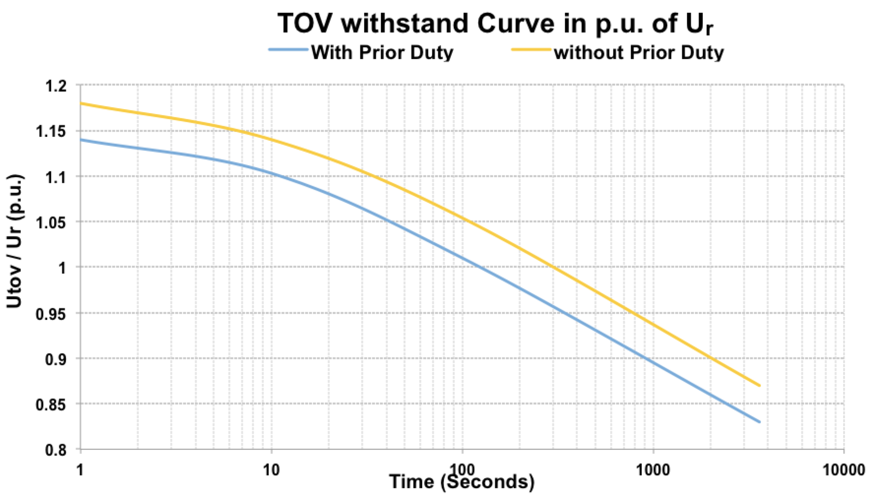
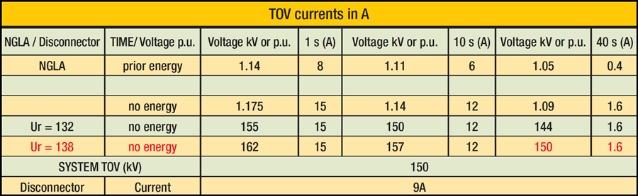
Typical TOV curves are presented as factors of rated voltage in Fig. 2. Two curves are shown – one with preheating due to a prior energy input before the arrester is exposed to the TOV. The other shows the TOV capability when the arrester is at maximum ambient temperature (60°C). The higher the TOV, the higher the power frequency current that passes through the arrester. The most critical case is when there is an earth fault on one phase and the healthy phases see the increased voltage until the fault is cleared. The NGLAs in the healthy phases will then follow the TOV withstand of no prior duty. The extreme non-linearity of the ZnO-arresters means that, for shorter times, the conductive area of the characteristics will apply. For very short TOV durations, the arrester might draw tens of amperes, which may be of the same magnitude as the short circuit currents at the NGLA’s point of installation. Based on prior TOV testing, arrester manufacturers typically know what currents are decisive for different durations.
To ensure that TOV stresses do not interfere with short-circuit currents, it is necessary to know the TOV requirements in actual kV of the system. These voltages are then recalculated to factors of the rated voltage selected for the NGLA. The mitigation is selecting a high enough rated voltage that immediately provides higher TOV withstand in kV and therefore lower currents. For example, the details of one particular NGLA installation may help clarify some of the above points. The installation involves a 145 kV non-directly earthed system with a reclosing time of 500ms. TOV conditions are 150 kV during 1s. The substation arresters have a rated voltage of 132 kV. From Fig. 1, it is evident that the disconnector needs a minimum current of 9A to operate within 500ms – which should be enough even for a far-distant location. A 132 kV rated arrester will have a TOV withstand of 150 kV (1.14 p.u.) for 1s for prior duty (see Fig 2). What needs to be known is what current a TOV of 150 kV will draw. That current will have to be lower than 9A so that there is no premature operation.
The current drawn depends on actual rated voltage of the NGLA so the TOV stress that draws 9A should be examined. It is seen from Table 1 that, for no prior duty, a 132 kV NGLA will draw 12A. A rated voltage of 138 kV is selected instead. Here, a 150 kV TOV is only 1.09 p.u. of rated voltage. As such, current is below 2A, which will not interfere with disconnector operation. A selection of 138 kV rated voltage will be the proper solution here, with maximum residual voltage at 20 kA of 387 kV. Adding 30% yields 503 kV – still ample margin given a typical BIL of 650 kV.
For a number of reasons it is advantageous to select a higher rated voltage for the NGLA compared to the substation arresters. This ensures that the NGLA is there only to prevent lightning flashover on its tower and not to handle switching, capacitor discharges or TOV stresses from the system itself. Another advantage is that grading rings can be smaller for higher rating. A common misunderstanding is that an NGLA for lightning protection should be selected based on the same specification as substation arresters.
Mechanical Considerations
Installing LSAs that hang directly from power lines also requires examining various mechanical considerations. Such an installation method is quite common these days and can also be used for live line installation. Overhead lines typically have dampers installed at predetermined positions around the line insulators or along the conductor to control vibrations and swinging. If LSAs are installed without considering these, their positive damping effects can diminish. Typically, line dampers should be placed on either side of an NGLA but the distance between them may need to be calculated in each case. A CIGRE Working Group looked into how best to install LSAs without distorting the mechanical properties of the lines or the units themselves.
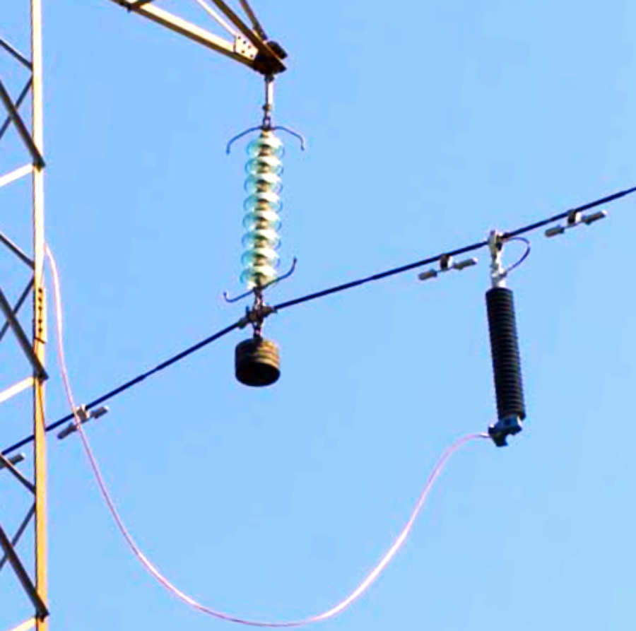
Sometimes weights are hung under insulators to stabilize a line. This same solution can also be used with NGLAs such that the weights hanging below them function as dampers for the line. It is important, however, to allow enough free movement of disconnector cables so that line vibrations do not fatigue the earth leads.
Case Study: Shielded 230 kV Double Circuit O/H Line
Computational models and methodologies have been developed to evaluate the lightning response of overhead lines. Today, specific software and programs are available that help users to select energy class, position and on which phases LSAs should be installed to best effect. As such, LSA characteristics as well as the procedures to optimize quantity and application points are obtained through transient studies. Basically two different studies have been performed:
1. estimating transmission line lightning performance for different configurations;
2. defining the energy level absorbed by the LSA considering lightning characteristics, grounding system behaviour for fast transients and probability of multiple strokes.
Starting with results obtained through theoretical studies and knowing the target number of outages desired for the overhead line being evaluated, it becomes possible to define the methods and procedures most appropriate to improve a line’s lightning performance. Such a technical evaluation should ideally be followed by an economic analysis that allows the user to analyse and optimize costs and benefits.
This case study highlights the impact on back-flashover rate of an NGLA configuration installed on a section of a shielded double circuit 245 kV line running 201.4 km, with different values of tower footing resistance. The following assumptions were used in the lightning analysis for this section:
• line insulation critical flashover voltage is 1040 kV;
• ground flash density is 6.7 strokes/km2/year;
• average soil resistivity of 1500 Ω.m;
• average span is 320 m;
• tower surge impedance is 198 Ω;
• rated voltage of NGLA is 198 kV.
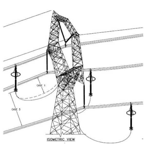
Fig. 3 shows the geometrical configuration of towers for the section, with the disposition of shield wires and phase conductors. Two different targets can be obtained during such a lightning analysis for a double circuit overhead transmission line:
Case 1: To reduce total tripping of the line for both circuits to a target outage level;
Case 2: To reduce or eliminate risk of simultaneous tripping of both circuits (i.e. double circuit flashover).
Double circuit flashovers on double circuit lines are usually highly detrimental to power quality and therefore most lightning analysis has been made based on avoiding such a situation. The simulation, here, was done using the Sigma SLP program. A total of 1000 statistical cases were used for each value of tower footing resistance and NGLA installation configuration. Total line flashover rate and double circuit rate for different arrester installations were evaluated.
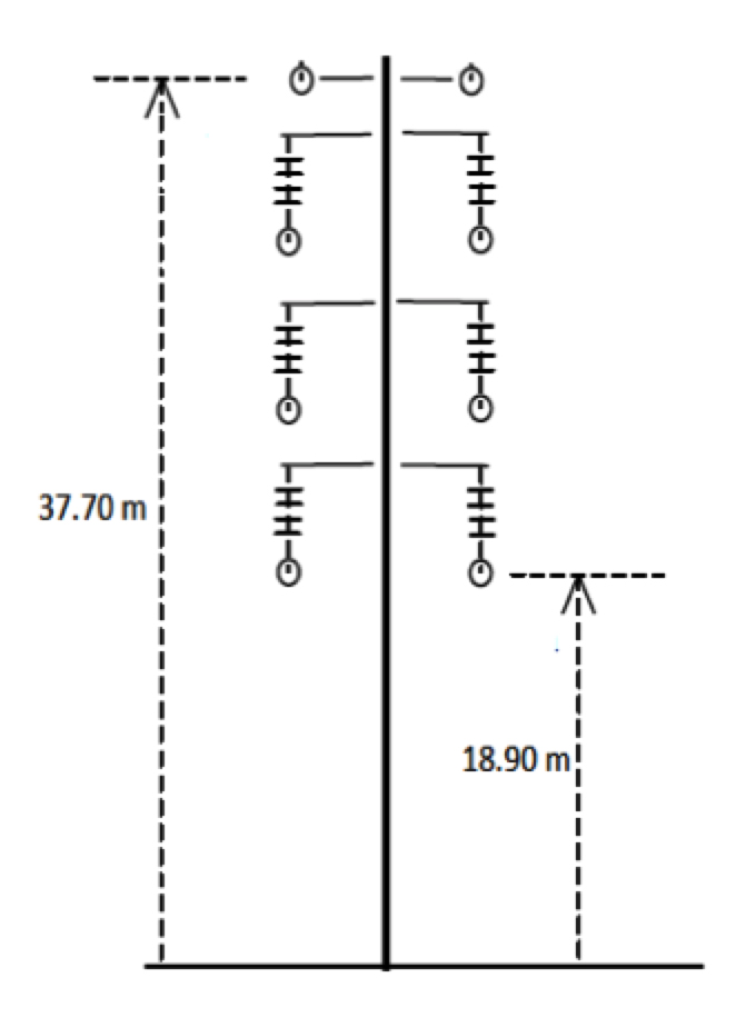
Fig. 4 shows the results of simulations presenting total line flashover rate in terms of flashovers/100 km/year for different tower footing resistance values and NGLA installation configurations.
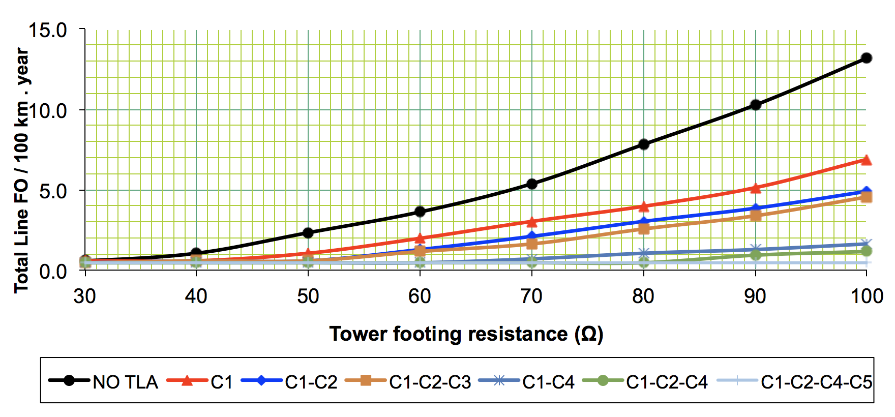

The figure of 0.46 flashovers/100 km/yr due to shielding failure obtained through these simulations for all configurations evaluated is considered total line flashover rate. To eliminate line flashover rate due to shielding failure, NGLAs would have to be installed on the top phases of both circuits. Information on line flashover rate due to back-flashover is summarized in Table 2.
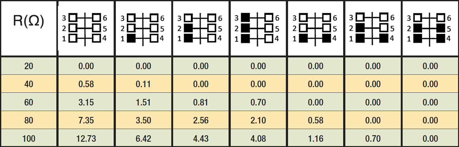
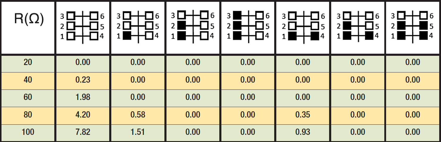
Fig. 5 shows the double-circuit flashover rate for the same conditions and summarized information can also be found in Table 3.
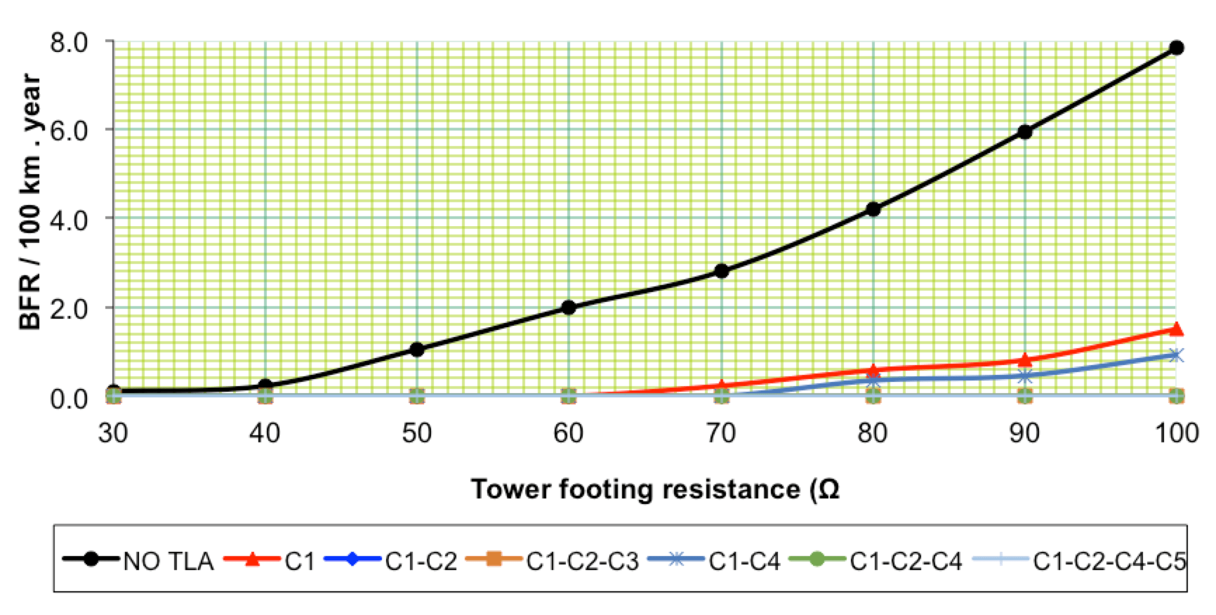
From Fig. 4 and Table 2, it is evident that an NGLA installed on the bottom phase of circuit 1 (C1) virtually eliminates line back-flashover rate for tower footing resistance values up to 40 Ω. It also drastically reduces line back-flashover risk, even for higher values of tower footing resistance. An expected relative improvement of about 50% can be seen for tower footing resistance values of 50 Ω and above. Installing two NGLAs on the bottom phase of both circuits (C1-C4) virtually eliminates back-flashover rate for tower footing resistance values up to 60 Ω. There is also an expected relative improvement of more than 90% for tower footing resistance values of 70 Ω and above.
Three NGLAs installed on the bottom phases of both circuits as well as on the middle phase of one circuit (C1-C2-C4) virtually eliminate back-flashover risk for tower footing resistances up to 80 Ω, with an expected relative improvement of more than 95% for higher values of tower footing resistance. No tripping due to back-flashover was recorded during simulations with four NGLAs installed on the bottom as well as on the middle phases of both circuits.
Comparing total line flashovers due to back-flashover based on simulations with NGLAs protecting all phases on one circuit (C1-C2-C3) and only the bottom phase of both circuits (C1-C4), with tower footing resistance values above 80 Ω, better lightning performance is observed for the configuration that protects both circuits. This in spite of a lesser number of NGLAs, thereby justifying this configuration if the desired goal is reducing total line flashover rate.
However, as shown in Fig. 5 and Table 3 for this particular lightning analysis, protection of one circuit using three NGLAs (C1-C2-C3) virtually eliminates double-flashover rate – even when tower footing resistance values are 100 Ω. Technically, this is the best option in terms of an NGLA configuration when the target is to eliminate or reduce simultaneous tripping of both circuits (i.e. double-circuit flashover). In this specific analysis, even protection using two TLAs installed on the bottom and middle phases of one circuit offered superior lightning performance against risk of double-circuit flashover.
In the case of overhead lines with rated voltages up to 145 kV, a higher line flashover rate due to back-flashover occurs due to lower line insulation Critical Flashover Voltage. Here, good practice to improve reliability against lightning sometimes consists of protecting one circuit with NGLAs and increasing the Critical Flashover Insulation of the non-protected circuit. This reduces total line flashover rate and virtually eliminates risk of double-circuit flashover. For higher tower footing resistance values or in regions with higher Ground Flash Density, some lightning analyses at this voltage have reported one solution where there are three NGLAs protecting one circuit, the other being protected with one NGLA on the bottom phase and higher Critical Flashover Voltage for the other two phases.