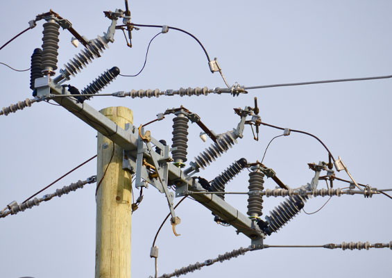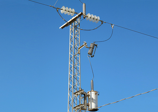
There are some 200 to 300 million distribution transformers in service worldwide. Of that population, a few hundred thousand are likely protected in a fashion similar to what is shown below, taken from a single-phase distribution line in North Africa. In this configuration, the arrester is protecting the two insulators at the top of the tower fairly well but offers virtually no protection for the distribution transformer located some 5 m below.
As explained in this edited contribution to INMR by arrester expert, Jonathan Woodworth, that is unfortunate since this arrester has probably been installed with the specific intent of protecting the transformer, being the most valuable asset on the tower. When it comes to surge protection, long arrester lead lengths are the ‘enemy’ simply because of their inherent inductance. In some cases, as here, they can even render the arrester almost useless.
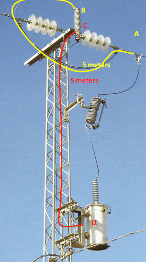
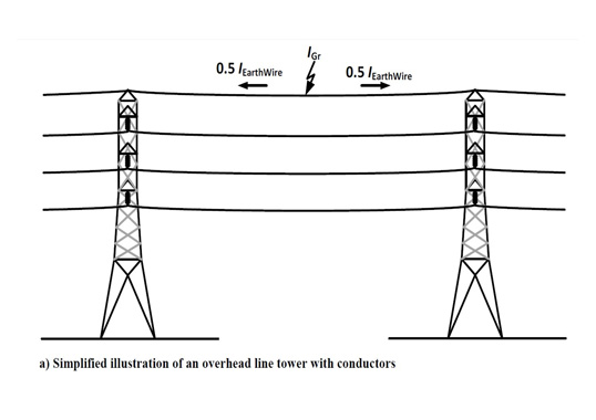
Determining what is the relevant lead length for an arrester is not always obvious and it is best to understand some general principles beforehand. Relevant lead length is that portion which carries the surge current into and out of the arrester and is in parallel with the protected insulation. In the example of the tower configuration shown in Fig. 1, the arrester line lead is from points A to B and the ground lead is from points C to D. These two leads would conduct the surge current into and out of the arrester and are electrically in parallel with the transformer. The leads into and out of the transformer are not relevant since they do not conduct surge current.

The reason lead length is so important is because inductance is almost entirely a function of it and nothing else. The voltage across the lead (and subsequently across the transformer) is calculated as E = L x di/dt, i.e. the product of the inductance and the rate of change of the current. Therefore, for fast rising surges, the voltage across the lead will be higher than in the case of slower rising currents. When referring to lightning surge, the time to crest of the first stroke is generally 5 to 10 µS duration and the second and subsequent rise times are 0.1 to 2 µs.
To demonstrate the negative impact of long leads, an ATP model was developed using the configuration in the photo and a simulation was run (T1) showing two lightning strokes hitting this line – the first at 0 µs and the second following close behind at 20 µs. Moreover, as part of the simulation, a 30 kA, 10 µs was used to crest current impulse for the first stroke and a 15 kA, 1 µs to crest impulse current for the second. This helps demonstrate the effect of surge steepness.
Based on the photo, some 5 m of lead is estimated above and similarly about 5 m of lead below the arrester, i.e. carrying surge current and at the same time in parallel with the transformer. A second configuration (T2) was then modeled and simulated with the arrester mounted on the transformer but this time with only a 0.3 m lead above and below the arrester. In both cases, a typical 7.2 kV Uc arrester was selected. Fig. 2 shows the results plotting voltage across the transformer insulation for both configurations.

As can be seen, the red trace (T1- long leads and slow surge) results in a 50 kV peak voltage at 7.5 µs while the fast surge on the long lead configuration develops a 281 kV peak voltage across the transformer after 21 µs. In the second simulation based on short arrester leads (shown as the green trace, T2), it can be seen that the maximum voltage stress on the transformer during the fast surge is only 38 kV. That means there is a difference of around 245 kV of electrical stress on the transformer due simply to the arrester leads.

This example demonstrates why there is a clear trend in transformer protection to locate the arrester directly on the tank. The only concern in such a mounting arrangement versus on the tower cross arm is the fuse rating of the cutout. To ensure that a lightning surge does not blow the fuse in the tank-mounted configuration, most utilities have adopted the practice of either increasing the fuse rating by a few amps or using a slower operating fuse. With the former solution, nuisance fuse blowing will no longer be an issue in the tank-mounted arrester scheme.
How do shorter lead lengths save money and combat climate change?
With the simple, low cost solution described above, utilities can effectively mount arresters closer to the transformer to achieve maximum protection. Avoiding transformer replacement is really the basic function of surge arresters but allowing long leads in the circuit effectively eliminates much of the arrester’s value. Transformer replacement, added down time, increased production of transformers – all can be kept to a minimum with obvious savings as well as in tons of reduced CO2.