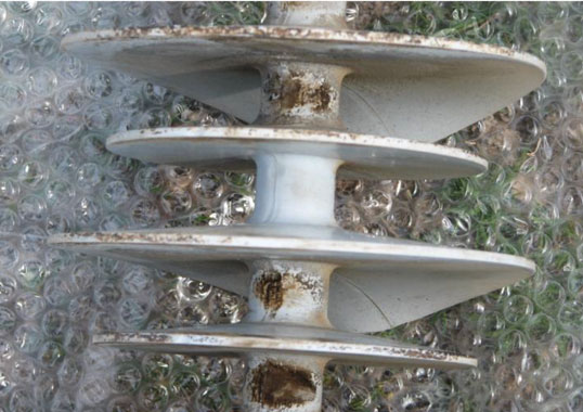
As composite insulators have matured into a mainstream choice on overhead lines, one of the strategic issues for transmission system operators is how best to manage their condition and risk at a fleet scale.
This edited contribution to INMR by Kübranur Varli of Amprion in Germany as part of a European R&D consortium led by I2G and 11 utilities, aimed to answers the following key questions:
• how to collect and analyze service experience to trigger appropriate maintenance actions;
• what types of maintenance composite insulators require; and
• how to evaluate the remaining service life and decide on corresponding interventions.
The end goal is to define optimal corrective maintenance procedures, developed through a structured, multi-step program.
The work first establishes practical, standardized guidance for collecting and interpreting field data to support maintenance decisions. It defines typical failure modes (e.g. pollution-induced flashover, flashunder, bird-induced flashover, electrical ageing including corona-driven mechanisms, and mechanical failure). It also offers advice on diagnosing these, starting with basic records and on-site visual observations and progressing to confirmation of root causes of possible failures and related actions.
Building on this foundation, the project identifies infrared, ultraviolet, and visual inspections as presently being the most effective diagnostic approaches, reflecting the prominence of flashunder caused by weak core-to-housing adhesion and/or inadequate rod quality. Such internal defects accelerate under elevated electric fields and therefore must be verified.
These methods were validated through ground-based inspections of more than 500 insulators across 3 countries, covering 1 to 30 years in service, clean and polluted environments, AC and DC applications, and voltage levels from 110 to 500 kV, thereby providing further input to corrective maintenance decisions.
In its final phase, the project linked condition assessment to actionable maintenance through laboratory investigation of 33 composite insulators representing 8 designs in the 66 to 400 kV classes, with service histories up to 40 years. A comprehensive post-service test matrix—comprising visual inspection, pollution parameters, hydrophobicity, hardness, core-to-housing adhesion, dye penetration, sealing cross-sections, and corrosion of fittings and seals—revealed clear differences between insulator batches and supported practical recommendations for corrective maintenance.
The outcome has been an optimized after-service test matrix that underpins asset management strategies and, ultimately, a maintenance guide structured around condition-based maintenance.
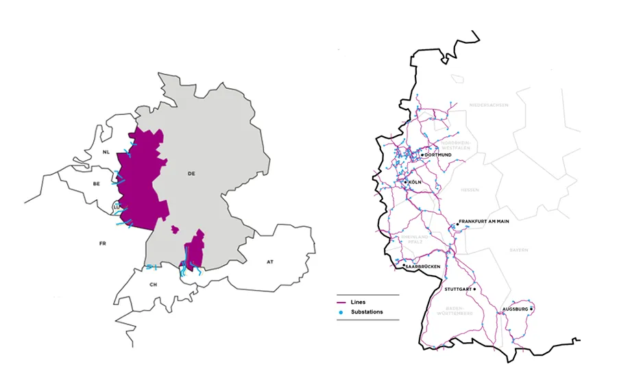
Amprion is one of Germany’s four transmission system operators, responsible for the long distance transport of electricity at extra high voltage. Its 11,000 kilometre grid stretches from the North Sea to the Alps, serving around 29 million people in a region that generates about one third of Germany’s economic output. Within this legally defined control area, Amprion plans, expands, and maintains the grid, operates the system, and safeguards overall power system stability—acting as a vital backbone for society and industry.
To enable energy transition and support industrial decarbonization, Amprion will invest approximately €36.4 billion in grid expansion through 2029. About 3100 employees are delivering a program to upgrade and extend some 9300 kilometers of transmission infrastructure, strengthening security of supply and creating capacity for renewables. The network is closely integrated with neighboring countries via interconnectors to the Netherlands, Belgium, Luxembourg, France, Austria, and Switzerland (see Fig. 1). These “power bridges” enhance system security and lower overall electricity costs in Europe. Among Germany’s TSOs, Amprion operates the most interconnectors.
Composite Insulators at Amprion
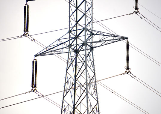
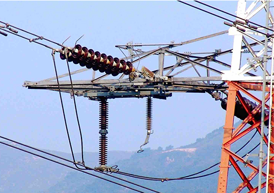
Since 2008, Amprion has exclusively used composite insulators for every new construction and refurbishment project, creating a large installed base and gaining expanded operational experience. Today, Amprion has approximately 60,000 composite insulators in its network. Confidence in their performance grew to the point that, in 2019, Amprion introduced a new tower framework family tailored to composites, moving away from designs that retained the option to revert to ceramics. This technology offers clear benefits: smaller towers that require reduced rights of way, facilitating easier permitting and improving public acceptance; lighter components that streamline logistics and installation; and enhanced durability that boosts reliability while reducing lifecycle costs. At the same time, the sheer number of units now in service makes effective maintenance strategies essential: even low individual failure rates can translate into material fleet level risk if not managed proactively.
Maintenance of Composite insulators
To enhance understanding of maintenance procedures for composite insulators under varying requirements and service conditions—and to use optimal maintenance strategy and technical specifications—Amprion participated in the R&D consortium project “Maintenance of Composite Insulators”. This was led by Independent Insulation Group (I2G) along with 11 European TSOs and DSOs: 50 Hertz (Germany), APG (Austria), Energinet (Denmark), E.ON (Germany), Fingrid (Finland), Red Electrica (Spain), RTE (France), Statnett (Norway), Svenska Kraftnät (Sweden), and TenneT (Germany). This consortium provided an effective forum for a broad and open exchange of experiences, as well as a solid foundation for collecting diverse samples for testing.
Goal
The consortium project aimed to deliver optimized maintenance procedures for composite insulators and was supported by two earlier projects that enabled improved purchase specifications, better selection of suitable insulator designs, verifying manufacturing quality, and better management of storage and installation. With large, diverse fleets already in service, the remaining needs are.
1. to standardize how service experience is collected and analyzed;
2. to define appropriate maintenance actions, and
3. to evaluate residual service life to support timely interventions.
The project was organized into 3 parts:
Part 1 establishes principles and recommendations for collecting and analyzing service experience to identify dominant field issues and their root causes, providing a structured evidence base for maintenance decisions.
Part 2 reviews and benchmarks contemporary diagnostic methods for condition assessment, with emphasis on the dominant failure mechanism and evaluates each technique by detection effectiveness, degree of standardization, required operator skills, and suitability for deployment from the ground, a tower, a drone, or a helicopter.
Part 3 analyzes results from after-service tests and proposes a practical after-service testing program, including a test matrix for the maintenance guide, to assess condition and remaining life effectively and to trigger the appropriate maintenance actions. Together, these deliverables provide a coherent framework for condition-based maintenance and life-cycle management of composite insulators.

Failure Mode Analysis & Corrective Maintenance Actions
The first part of the project set out recommendations for systematically collecting and analyzing service experience to support maintenance decisions on composite insulators. It identified 6 recurrent failure modes:
• pollution-induced flashover,
• flashover of unknown origin,
• flashunder,
• bird-induced flashover,
• electrical (corona-induced) ageing, and
• mechanical failure
and provides practical guidance for diagnosing each. The approach leads practitioners from assembling basic event information and in-service visual observations, through targeted checks to confirm the root cause, to the corresponding corrective or preventive actions. This is provided in the format of pictorial guidelines.
Three of these guidelines are presented below:
1. Flashunder
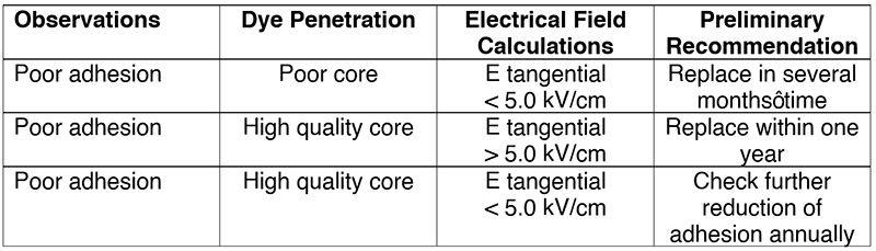
Based on service experience and recent after-service tests, flashunder has been identified as the dominant failure mode for composite line insulators. It initiates as a dielectric breakdown at the core-housing interface, typically due to poor adhesion, with moisture condensing in interfacial voids and partial discharges propagating as a semi-conductive path. Depending on rod quality, this develops as interfacial tracking or progresses to semi-conductive rod erosion and, in severe cases, decay-type fracture. As the path advances, corona raises surface fields, hydrophobicity degrades locally, punctures appear, and the final breakdown transitions to an external flashover.
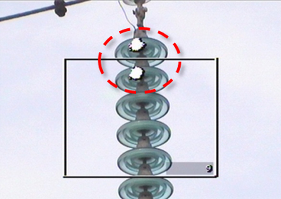
Analysis proceeds from field evidence to confirmation. Visual cues include localized whitening/hardening of silicone near the high-voltage end and small housing punctures. Infrared thermography is the primary confirmation method, preferably during or after humid periods; the temperature rise, and profile indicate defect location and progression. UV imaging complements IR by revealing intense corona and punctures. Root-cause verification relies on adhesion assessment: quick field checks (stripe or shear-strip) to distinguish cohesive from adhesive separation, followed by more accurate laboratory methods (water-diffusion preconditioning with AC withstand and a pull-off strength test), and a dye-penetration test to screen possible rod porosity. Because overstress accelerates degradation, 3D electric-field calculations should be used to verify grading and, if needed, to optimize corona/grading rings.
Actions prioritize safety and fleet risk: remove units with punctures, rapidly growing IR hot spots, or confirmed poor adhesion; quarantine affected batches and test samples; increase IR patrols in humid seasons; retrofit grading hardware where fields are high; and, if batch-level adhesion issues are confirmed, plan staged replacement, and engage the manufacturer. All observations, measurements, and decisions should be recorded in the database to refine thresholds and replacement criteria across the fleet.
2. Electrical Ageing, Corona-Induced Ageing
Ageing-related deterioration of composite insulators is divided into corona-induced and environment-induced mechanisms, and analysis proceeds from concise context capture to targeted confirmation and proportionate actions.
Assessor documents are timestamp and weather (humidity/wetting), service voltage and loading, site pollution indicators, insulator type and geometry, and clear photographs. For suspected corona-induced ageing, visual checks focus near the high-voltage end fitting and metal parts for localized whitening/hardening of silicone, pitting or burn marks, and tracking aligned with field stress, typically where corona/grading rings are absent, undersized, or mispositioned.
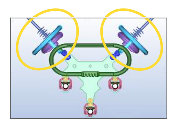
Confirmation relies on daylight UV imaging and 3-D electric-field calculations including insulator, fittings, rings, tower, and conductors, benchmarked against common limits (<18 kV/cm on rings/fittings and <4.2 kV/cm tangential on the housing, averaged over 10 mm as per the latest IEC 61109), with a water-drop corona test used where needed.
Recommended actions are to correct grading hardware (add/reposition rings, smooth edges), replace units with deep erosion or tracking, and verify mitigation with follow-up UV patrols in wet seasons. For environmental-induced ageing, broader exposure-driven changes are sought—chalking or color fading, surface roughening, biofouling, hydrophobicity loss, and tracking/erosion along leakage paths (shed lips, trunk); confirmation includes prompt Hydrophobicity Class measurement (IEC 62073, Method C), pollution measurements, infrared thermography if internal heating is suspected, and, where recovery is slow, a simple dynamic hydrophobicity test to compare material families.
Actions are graded: leave or monitor when ageing is cosmetic and hydrophobicity remains high; investigate further when evidence is mixed; replace or correct when tracking/erosion progresses, hydrophobicity is persistently low, or geometry/creepage is inadequate. Recommended mitigations include washing or cleaning, upgrading to profiles compliant with higher USCD requirements per IEC 60815-3, and selecting more robust silicone material families.
All observations, measurements (UV/IR, HC, ESDD/NSDD), calculations, and decisions are recorded in a database to track trends, benchmark mitigation effectiveness, and refine maintenance strategies.

3. Pollution-Induced Flashover
A balanced procedure for assessing suspected pollution induced flashovers begins with compiling the basic event record (timestamp, location, service voltage, and on site observations) and applying IEC 60815 1 to frame the problem.
Service evidence is then used to test plausibility: inspect insulator for leakage current traces that follow the surface path to distinguish pollution events from lightning; check time of day correlations (in Europe, events often occur at night or early morning under high humidity); and cross reference the outage time with weather data for coincident wetting (dew, fog, drizzle, light rain, wet snow, conductive rain) and pollution drivers (onshore sea salt transport, local industrial sources, etc. Consult lightning detection data, noting that in Europe lightning typically peaks later in the day and leaves characteristic marks.
Design adequacy is then verified against IEC 60815 3 by checking the unified specific creepage distance (USCD) against site pollution severity (SPS), with altitude and diameter corrections, as required. If SPS is unknown, it can be estimated using IEC 60815 1 guidance.
Material and surface condition should also be assessed. Measure Hydrophobicity Class (IEC 62073, Method C) promptly after de energization to limit bias from rapid recovery and document any biological growth that can depress hydrophobicity locally. Quantify contamination by measuring ESDD/NSDD on top, bottom, and trunk at several positions, recording both weighted averages and maxima. Observe discharge activity during humid or windy periods with UV imaging or visually; blue/violet corona indicates low current activity, whereas yellow/orange partial arcs on NaCl contaminated surfaces signal a pre flashover state.
Actions flowing from the findings are:
• upgrade under dimensioned strings to higher USCD, IEC compliant profiles and correct marginal geometries;
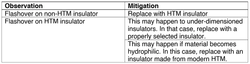
• clean or replace units with persistently low hydrophobicity or poor recovery (consider more robust HTM families);
• schedule targeted inspections and washings for high risk weather windows (e.g. coastal spray seasons);
• deploy permanent pollution monitoring to refine SPS; and
• document all measurements, images, and conclusions in a database to enable correlation studies and condition based fleet planning.

Summary
In summary, a structured framework for collecting and analyzing service experience to guide maintenance of composite insulators has been delivered, covering 6 recurrent failure modes: pollution induced flashover, flashover of unknown origin, flashunder, bird induced flashover, electrical (corona induced) ageing, and mechanical failure. It standardizes workflows from basic event capture and visual inspection to targeted confirmation and actions. All evidence is logged in a database to enable benchmarking and condition based fleet planning.
Part 2 of this contribution will appear in the INMR WEEKLY TECHNICAL REVIEW of Nov. 24.
References
[1] M. Jalonen, K. Välimaa, I. Gutman, A. Deckwerth, K. Halsan, M. Leonhardsberger, L. Diaz, P. Trenz, K. Varli: “Benchmarking Composite Insulators: Utility Perspective & European Initiative”, 2023 INMR World Congress, Bangkok, Thailand, 12-15 November 2023
[2] I. Gutman, J. Lundengård, A. Deckwerth, L. Diaz, K. Halsan, M. Jalonen, F. Lehretz, M. Leonhardsberger, L. Rasmussen, P. Rodriguez, T. Schiml, K. Varli, D. Windmar: “Condition-Based Maintenance of Composite Insulators Using Optimal After-Service Test Matrix”, 2025 INMR World Congress, Panama City, Panama, 19-22 October 2025
[3] I. Gutman, J. Lundengård, A. Deckwerth, L. Diaz, K. Halsan, M. Jalonen, F. Lehretz, M. Leonhardsberger, L. Rasmussen, P. Rodriguez, T. Schiml, K. Varli, D. Windmar: “Condition-Based Maintenance of Composite Insulators Using Optimal After-Service Test Matrix”, 2025 INMR World Congress, Panama City, Panama, 19-22 October 2025
[4] P. Sidenvall, I. Gutman, L. Diaz, A. Deckwerth, K. Halsan, M. Jalonen, F. Lehretz, M. Leonhardsberger, L. Rasmussen, P. Rodriguez, T. Schiml, K. Varli, D. Windmar: “Inspection of composite insulators as an input into preventive maintenance”, CIGRE Science & Engineering
[5] I. Gutman, J. Lundengård, P. Sidenvall, A. Deckwerth, L. Diaz, J.-F. Goffinet, K. Halsan, M. Leonhardsberger, M. Radosavljevic, P. Trenz, K. Varli, K. Välimaa, M. Heath, R. Davey, W. Vosloo: “Condition assessment of line composite insulators: after-service test programs and their practical application”, CIGRE Science & Engineering, N. 28, 2023, p.p. 1-37
[6] CIGRE TB 481: “Guide for the Assessment of Composite Insulators in the Laboratory After their Removal from Service”, 2011
[7] I. Gutman, J. Lundengård, F.A. Machuca, D. Lepley, N. Kita, H. Homma, K. Kondo, T. Nakachi, S. Slimani, W. Manzke, P. Carlsson, Y. Wang, B. Robben, G. Lassu: “Evaluation of repeatability and reproducibility of the new-developed hydrophobicity transfer test for polymeric insulators”, ISH-2025, Karuizawa, Nagano, Japan, 24-29 August 2025, paper C3_1_30
[8] P. Sidenvall, J. Lundengård, I. Gutman, L. Diaz, A. Deckwerth, K. Halsan, M. Jalonen, F. Lehretz, M. Leonhardsberger, L. Rasmussen, P. Rodriguez, T. Schiml, K. Varli, D. Windmar: “Application of New Test to Evaluate a Key Parameter of Composite Insulators Hydrophobicity Transfer”, CIGRE Symposium, Montreal, Canada, 29 September – 2 October 2025, 10612
[9] K. Varli, S. Steevens, J. Unterfinger, A. Dernfalk, I. Gutman, J. Lundengård, P. Sidenvall: “Benchmarking of sealing systems of composite insulators: ideas for innovative test methods” CSE, N. 25, pp. 108-131, June 2022