HVDC overhead lines are highly efficient assets when it comes to long-distance transmission of bulk power and are beneficial with regards to performance as well as rapid maintenance. OHL technology is also state-of-the-art and the most cost efficient in terms of Total Cost of Ownership.
Over the decades, various insulator technologies, i.e. porcelain, glass, composite, have been applied worldwide under different environmental and pollution conditions. Best long-term insulation performance has been achieved with hydrophobicity transfer materials (HTM) as per IEC TR 62039, these being either silicone composite types or RTV coated porcelain or glass insulators.
The edited contribution to INMR by Dr. Jens Seifert at TKE in Germany in co-operation with Christoph Purucker and Amit Karanth at Lapp Insulators presents results of a study on porcelain longrod insulator strings for application on HVDC OHLs. The study compared past data for alternative insulation technologies, pollution tests, design, field applications and performance calculations.
Historical Overview
Overhead line insulation for HVDC has been realized mainly using cap & pin (disc) type or silicone composite insulators while application of porcelain long rod insulators (PLRIs) is still relatively rare. This has been due mostly to historical, not technical reasons.
When the first HVDC lines were commissioned in Russia in 1951 (Moscow-Kashira) and in Sweden in 1954 (Gotland), these were equipped with glass disc as well as porcelain long rods. Both insulator types met all requirements at the time for the ±100 kV voltage class. Later, with the Volgograd-Donbass scheme in the USSR (1965), the 400 kV level was achieved, and glass disc type insulators were again applied, mainly because there was domestic production. Between 1950 and 1975, DC schemes were built in Scandinavia up to ±440 kV. These used large numbers of glass disc and porcelain long rod insulators, both of which showed good service performance. In fact, most of these are still in service. Again, the main reason for the choice of insulators was that Norway, Denmark and Sweden operated modern plants allowing domestic supply of PLRIs.
The 1970 Pacific ±400 kV Intertie interconnection in the Western U.S. was originally equipped entirely with glass disc insulators until widespread pollution related problems began. These started first at the Sylmar HVDC Converter Station near Los Angeles with flashovers of station post insulators. Mitigation methods at the time involved temporary reduction in operating voltage to ±350 kV and, for first time, application of RTV silicone coatings to station posts. But as pollution accumulated, line insulators also began to experience local flashovers under critical conditions.
In 1984, silicone composite insulators with HTM properties were installed on this line. These proved a key success and enabled the line to be uprated to ±500 kV and later, in 2013, to ±560 kV. This changeover campaign (as well as a similar one to ±533 kV by replacing glass disc insulators with silicone insulators at Cahora Bassa in Mozambique) was driven largely by the Rosenthal Insulator Company (later Hoechst Ceramtec) who were able to supply two kinds of long rod technology i.e. porcelain and composite.
At the time, for commercial reasons, Rosenthal chose to offer composite insulators in preference to PLRIs for HVDC applications. The reason for this appeared to have been more marketing than performance related since a contribution at the CIGRE 1982 Session discussed benefits of PLRIs for DC application – especially if the HTM feature was added by means of an RTV coating.
These days, despite the comparatively small share of PLRIs in HVDC applications, their performance has been well documented through extensive field experience. Moreover, recent developments in manufacturing and materials science have enabled these insulators to meet even the stringent requirements of modern HVDC systems, resisting environmental stresses and offering long service life. As the industry continues to evolve, PLRIs are increasingly recognized for their reliability and cost-effectiveness across demanding transmission applications.

Porcelain Long Rod Insulators
1. Mechanical Performance
PLRIs were developed prior to 1938 by Rosenthal and subsequently applied in high volumes on 420 kV and 750 kV overhead lines in Germany, Poland, Russia, Switzerland, Austria, Czech Republic and Scandinavia. In Germany, for example, more than 8 million units have been installed, most of these over 30 years in service. After 1970, PLRIs were also widely applied in the Middle East, India, Pakistan, Japan, North and South Africa.
PLRIs have since been offered by manufacturers in Germany, Austria, Switzerland, Russia, Scandinavia, Poland, Slovakia, India, Japan and China. In Germany alone, there used to be 7 PLRI manufacturers during the 1970s. More than 50 million units are now in service globally.
Over the past 40 years, CIGRE has conducted different studies and surveys regarding long-term performance and reliability of different types of insulators. The performance ranking from these studies suggested the following:
Rank 1: Porcelain long rod & glass disc insulators
Rank 2: Composite long rod insulators
Rank 3: Porcelain disc insulators
One study, for example, found that PLRIs offer highest overall reliability while a more recent study from 2024 showed that cap & pin glass discs offer superior long-term performance over porcelain cap & pin types. This was confirmed by research that showed no significant degradation in mechanical strength after more than 50 years – even for stubs, i.e. glass discs with lost shells from self-shattering. By contrast, porcelain disc type insulators showed significant degradation in mechanical strength over time, along with a high scatter in breaking loads.
The same performance has been documented for PLRIs, which show the lowest ppm failure rate among all types. According to IEC 60433/IEC 60383, PLRIs can be manufactured up to a strength class of 600 kN. Table 1 shows typical shank diameter classes.
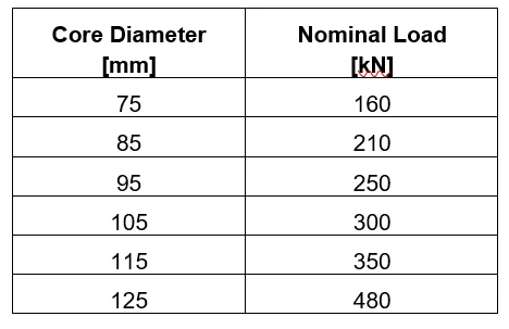
Typical unit length is 1100-2000 mm although longer units are also possible. For example, 3000 mm units were produced in the 1970s for single unit 380 kV insulation at German and Swiss utilities.

2. Electrical Performance
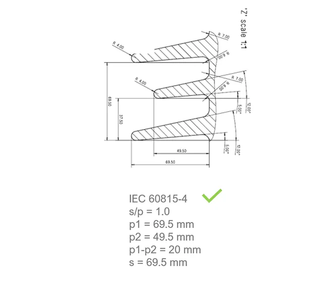
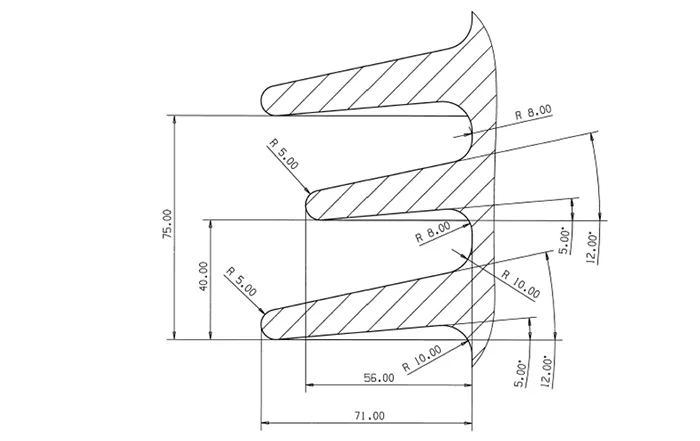
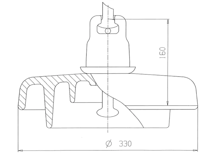
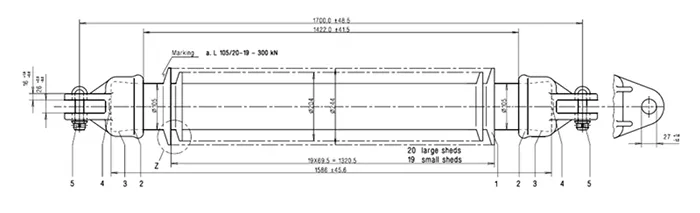
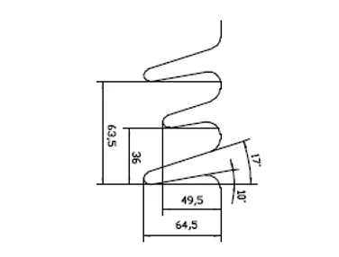
According to service experience and IEC 60815-2(AC)/60815-4(DC), a slim, open, aerodynamic profile with high creepage and high form factor (Ff) is preferred. Insulation designs of PLRIs for DC applications fall in the range 60…110 mm/kV without an RTV coating, depending on relevant site specification. Fig. 2 shows a typical, well-proven shed profile.
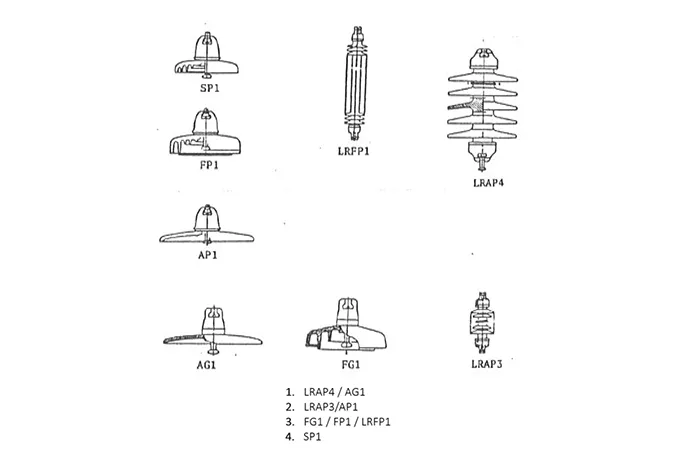
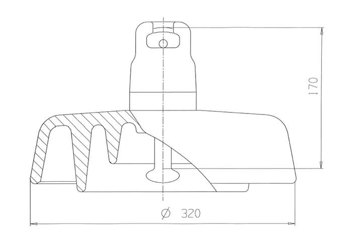
During the 1980s, studies were performed at outdoor pollution test stations in Saudi Arabia with evaluation based on flashover performance, leakage current and tripping events. Fig. 3 depicts the ranking with the best performance, i.e. a PLRI with smooth, aerodynamic sheds in alternating configuration for high creepage distance, as per IEC 60815-2. At the time, IEC 60815:1986 was not yet available and, in fact, results from this test station served as valuable input.
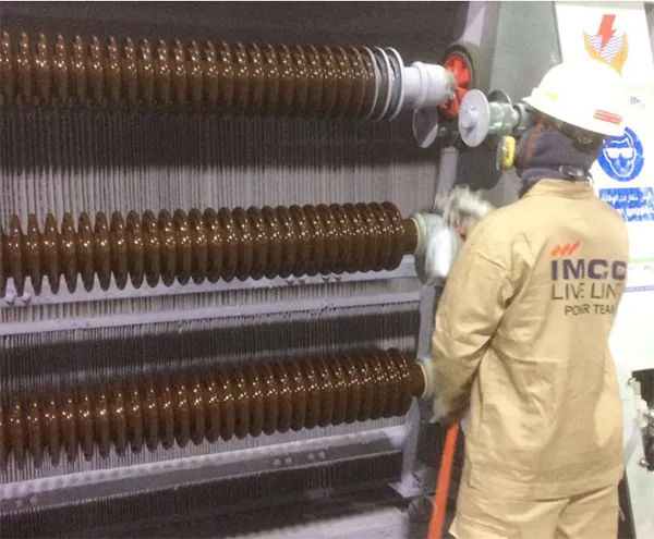
RTV Coatings
Room temperature vulcanizing (RTV) silicone coatings allow the normal hydrophilic surface of porcelain or glass to become a Hydrophobicity Transfer Material (HTM), as per IEC TR 62039. RTV coatings were first used as mitigation to resolve pollution related problems with porcelain and glass insulators at installations that suffered pollution flashovers. In most cases, coatings were applied in the field using a spray method. Since then, the process has been developed to allow ‘in-factory coating’. In the process, coatings have progressed from being solely a mitigation measure to becoming a product design feature (see Fig. 4). These days, RTV silicone coatings are available either in the classical solvent-based form or as more eco-friendly, water-based systems.
The resulting improvement in electrical performance due to application of a coating was studied by two CIGRE and one IEEE Working Group between 1995 and 2015, both in the field and at test laboratories. Table 2 presents the relative enhancement found in flashover performance.
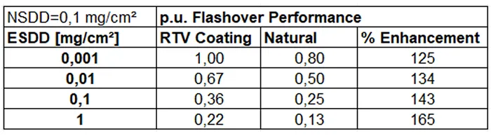
It can now be demonstrated that RTV coatings applied on PLRIs with slim profile (i.e. with high Ff) offer the same pollution performance as silicone composite insulators, assuming similar design criteria are applied for the shed profile.
Advantages
PLRIs offer advantages in HVDC applications:
• Same electrical performance as cap & pin type insulators (when correctly dimensioned for DC voltage stress and pollution requirements) for the normal hydrophilic porcelain (glazed) surface. AnRTV silicone coating transfers the hydrophilic nature of the porcelain surface into a HTM surface. This enhances performance by 25-65 % (equal to 1-1.5 Pollution Classes of IEC 60815) and, in conjunction with high form factor, Ff, yields the same pollution withstand characteristic as silicone composite insulators;
• No risk of metal end fitting corrosion – no zinc sleeve/collar required when coated with RTV silicone;
• Superior long-term mechanical performance;
• Superior electrical performance, especially with addition of an RTV coating;
• No risk of ageing or degradation;
• No risk of shatter of glass shell under DC stress;
• No puncture failure mode as with porcelain discs (Type B) since these are Type A according to IEC 60383-1.
Comparative Pollution Tests
The development and tender stage of the first re-insulation of the ±533 kV Cahora-Bassa Line from Mozambique to South Africa investigated different types of insulators. As part of this process, comparative pollution testing (i.e. the solid layer test acc. to IEC 61245) was performed at FGH/CESI in Germany. Figs. 5, 6 & 7 show details of the profiles tested (total string length 5440 mm for each type of insulator).

The linearity between pollution withstand voltage and overall length up to 600 kV DC has been already demonstrated by laboratory tests. As such, specific withstand voltage stress in terms of kV per cm is independent of test voltage.
Figs. 8 & 9 show results from these comparative tests, performed with the ‘up and down’ method acc. IEC 61245, to determine respective withstand and flashover voltage at different pollution levels (SDD).
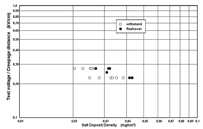
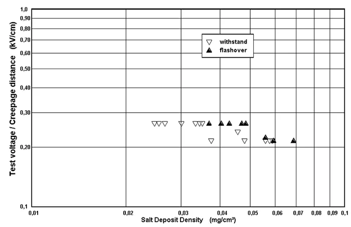
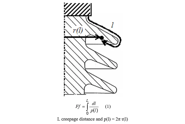
Fig. 9 compares the tested times by means of calculated ‘pollution curves’ depending on SDD (note the double logarithmic scale to assess the arc coefficient η). The mathematical relationship is applied as follows:

where uw is pollution withstand voltage standardized per creepage distance length and η is arc coefficient.
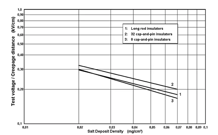
1: Long PLRI string with DC profile with η = 0.40
2: Long Glass disc string (AC discs) with η = 0.39
3: Short Glass disc string (DC discs) with η = 0.46
The lower the coefficient η, the better the pollution performance with increasing SDD. It can thus be derived that PLRIs and AC discs offer basically the same withstand performance while the DC disc type is slightly more affected by SDD (i.e. higher slope).
It can therefore be concluded that the same pollution performance can be achieved for HVDC using either disc type or long rod type insulators, if designed correctly for the respective application. This is confirmed by the positive service experience achieved with similar housing profiles used on station post insulators under HVDC stress (i.e. at converter stations).

HVDC Insulator Sets
Design creepage distance requirement for DC voltage stress is stated mainly in IEC 60815-4 or within a particular utility specification. This can range from light (30 mm/kV) to medium (40 mm/kV) to heavy (50-70 mm/kV), all the way to the most extreme site pollution conditions, i.e. more than 90 mm/kV. These values apply for hydrophilic surface conditions whereas, for HTM surfaces, creepage distance can be reduced by 25 to 60%.
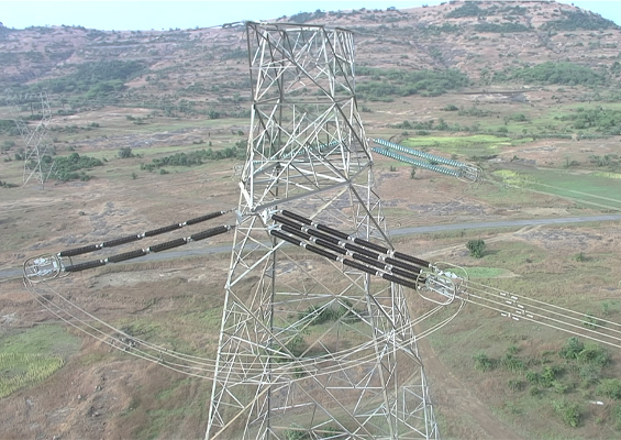
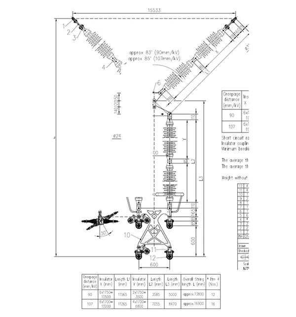
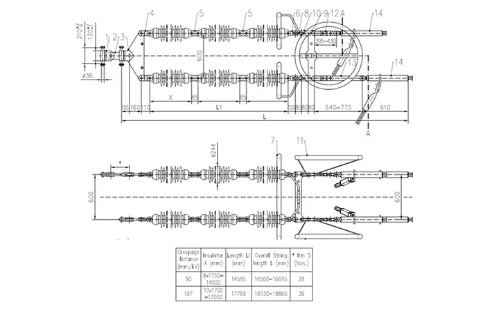
Alternatively, performance can be increased by the same amount if physical creepage is realized, as shown for suspension in the concept in Fig. 12 and for tension in Fig. 13. The PLRIs are designed with the same DC shed profile as in Fig. 2 and the sets are built up in a modular way using the same type of PLRI (see Fig. 10). All insulators in both sets would be equipped with RTV coatings, applied using a controlled in-factory process.

Installations & Service Experience
Although examples of installations of PLRIs on HVDC lines are relatively limited, there are nonetheless valuable references and reports of service experience. In Europe, for example, there are numerous HVDC cable connections between Scandinavia and Germany/Poland, that incorporate overhead line sections, e.g.:
Baltic Cable ±450 kV Germany (Lübeck) – Sweden (Kruseberg) where an overhead line section of 12 km sees PLRIs installed (see Fig. 13).
Nord Link ±525 kV Germany (Wilster) – Norway (Tonstad) has an overhead line section of 53 km.
LitPol ±525 kV Lithuania (Alytus) – Poland (Elk) features a160 km overhead line.
Good performance has been reported for PLRIs on all these lines, even without RTV coatings applied.
In India, PLRIs have performed well on the ±525 kV Chandrapur-Padhge Line where they were first installed in 1999 in a design having four 160 kN units per string (see Fig. 15).
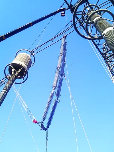
In Pakistan PLRI strings are in service on 525 kV smoothing reactor installations of mixed AC/DC voltage. These insulators are RTV coated and have operated without problem since 2009 (see Fig. 16). Coated PLRIs were selected in this case to replace silicone composite insulators that had failed shortly after installation due to tracking and erosion under the extreme pollution severity and mixed AC/DC voltage.
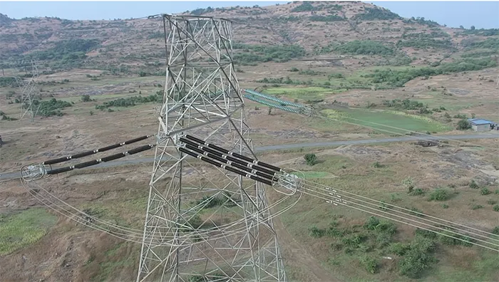
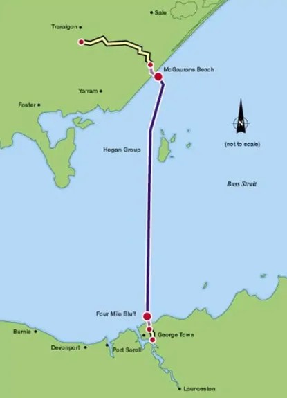
There is also long service experience with a relatively large number of PLRIs on the ±400 kV HVDC Bass Link Project between Australia and Tasmania (see Fig. 17). The major portion of the line consists of submarine cable but there is also a 73 km overhead line section. Site conditions on this overhead line, commissioned in 2006, are severe due to the marine environment.
The PLRIs were first installed without RTV coatings, as were the insulators at both converter stations, i.e. porcelain posts and disc insulators. Numerous flashovers occurred after energization and the operator decided to apply RTV coatings to all insulators on the line and in the substations/converter stations. After this mitigation, no flashovers and line outages due to pollution were reported. The general performance records for this DC scheme are good, with no ageing, degradation or corrosion being detected. The design data for this Project, as built, was as follows:
1. PLRI Profile:
s/p = 0,98
CF = 4,24
C = 56 mm
p1-p2 = 15 mm
Complies with IEC 60815-4 (even though standard was published 10 years later)
2. PLRI String Design:
h1 = 1350 mm
Total string length = 5400 mm
CD per unit = 4409 mm
4 units per string
Total CD = 17636 mm
SCD = 44 mm/kV
No RTV Coating / No HTM
3. CLRI String Design (Silicone Rubber Composite, Reference Installed at Converter Station):
h1 = 4170 mm
CD per unit = 4409 mm
1 unit per string
Total CD = 17670 mm
SCD = 44 mm/kV
Silicone Rubber / HTM
Even as far back as 2006, all profile parameters complied with the subsequently published IEC 60815-4 (2016). However, an SCD of 44 mm/kV was insufficient for non-HTM surfaces both at Bass Link stations and on the overhead line section. With enhancement to achieve an HTM surface by applying RTV coatings, this same SCD of 44 mm/kV proved sufficient to effectively avoid pollution flashovers on both station posts and PLRIs.
Conclusions
1. Porcelain long rod Insulators are highly reliable from a mechanical perspective and on the same level as high-quality glass disc insulators. This has been confirmed by past CIGRE studies.
2. More than 50 million PLRIs are already in service worldwide on AC overhead lines. The age of these installed units is, on average, more than 30 years. Installation for HVDC OHLs exist, but are still at a relatively low level, not for technical but rather for past commercial reasons.
3. PLRIs experience no mechanical or electrical degradation over time. Moreover, there is no principal failure mode with the C120/C130 porcelain material grades that have been applied for PLRIs since the early 1970s.
4. Electrical performance of PLRIs without an RTV coating is the same as or better than that of disc type insulators, assuming housing profile has been selected correctly. This is due to high form factors related to slim high-creepage designs and has been confirmed by artificial pollution testing under DC stress, comparing different types of insulators.
5. If PLRIs are coated with RTV silicone material, their performance is enhanced in the range of 25 to 60%, making it comparable to that offered by silicone composite insulators. This positive effect is due to transition to an HTM surface characteristic.
6. Existing references and service performance assessments have demonstrated that RTV coated PLRIs with an open, aerodynamic profile are effective solutions for harsh pollution conditions, even under DC voltage stress. Since leakage currents are negligible, additional corrosion protection by zinc sleeves or collars is not required.
7. All these advantages can be demonstrated by tests, investigations and review of the literature.
References
[1] E. Bauer, H. Dietz; Porcelain and Composite Long Rod Insulators – A Solution for Future Line Requirements, IEEE Transactions on Electrical Engineering, Volume EI-16, Issue 3, June 1981.
[2] V.V. Bourgsdorf; Study and Conclusions from the Results of the Enquiry on Insulators: Report on Conditions of Use, SC 22.03, Electra No. 2, January 1979.
[3] G. Marrone; Analysis of the Replies of the Questionnaire concerning the Use of High Mechanical Performance Insulators, SC 22.03, Electra No. 147, 1993.
[4] M. Zimmermann; Overview of Failure Modes of Line Insulators, INMR Magazine, Issue Q2/2024, July 26th, 2024.
[5] M.P. Verma, W. Petrusch, M. Prasad, W. Draeger; Use of Porcelain Long Rod Insulators in HVDC Transmission Lines, CIGRE Colloquium SC 33.39, Subject 2.2, Paris, France, 1982.
[6] J.M. Seifert, W. Petrusch and H. Janssen; Comparison of the Pollution Performance of Long Rod and Disc Type HVDC Insulators.
[7] F.M. Zedan, M. Akbar; Field Measurements of Various Pollution Assessment Parameters, King Fahd University of Petroleum and Minerals, Saudi Arabia, 1987.
[8] A. Abbasi, A. Sayegani, K. Niayesh; Pollution Performance of HVDC SiR Insulators at Extra Heavy Pollution Conditions, IEEE TDEI, Vol. 21, No.2, April 2014.
[9] L.L. Vladimirskii; The Development of the HVDC Systems in Russia, NIIPT, St. Petersburg, 2011.
[10] G.N. Aleksandrov, V.L. Ivanov; Electrical Apparatus Insulation, Energoatomizdat, 1984, 208 c.
[11] W.M. Ma et al.; Preliminary Recommendations on the Suitable Shed Profile for HVDC Station Insulators with Silicone Rubber Housing, Published on POWCON06, PaperDC1-07, C1538, Chongqing, China, 22-26.
[12] Wang Shaowu, Liang Xidong et. al; Influence of Shed Profile on the Outdoor Insulation Performance of Polymeric Insulators, Proceedings of 6th ICPADM, paper 785-788, June 2000.
[13] R. Matsuoka; S. Ito et. al; Contamination Withstand Voltage Characteristics of Polymer Insulators, 10th ISH, August 25-29th 1997, Montreal, Canada.
[14] CIGRE WG B2.03; Service Performance of Composite Insulators on HVDC Lines, Electra No. 161, August 1995.
[15] K. Kondo et. al.; Contamination Withstand Voltage Characteristics of Hydrophobic Polymer Insulators under Simulated Rain Conditions, Conference Record of the 2002 IEEE International Symposium on Electrical Insulation, Boston, MA USA, April 7-10, 2000.
[16] M. Marzinotto, G.M. George, G. Pirovano; Field experience and laboratory results on the application of RTV coating on HVDC lines, Paper B2-208, CIGRE 2020, Paris, France.
[17] APA; Bass Link Condition Assessment, Amplitude Document Number: PAU0359-REPT-001, 06 September 2023
[18] S. Bex et.al; Bass Link HVDC Provisions Supporting AC System Performance, Paper B4-301, CIGRE 2006, Paris, France
[19] A. Matte, J.M. George; Ageing Infrastructure Evaluation – The Evaluation of Aged High-Voltage Ceramic Suspension Insulators – Synthesized Analysis of In-Service Ageing Assessments, CIGRE Paper 842, CIGRE 2024 Canada Conference & Exhibition, Winnipeg, MB, Oct. 28-31, 2024.
[20] R. Gorur; RTV Coatings for Ceramic Insulators, INMR Magazine, Issue Q4/2024, December 26th, 2024.
[21] Kawamura T., Nagai K., Seta T., Naito K.; “DC pollution performance of insulators”, CIGRE-Report 33-10, 1984, Paris.
[22] Wacker AG, Powersil 567, Technical Data Sheet 2023, Wacker AG, Burghausen, Germany.
[23] Wacker AG, Powersil 577 Plus, Technical Data Sheet 2023, Wacker AG, Burghausen, Germany.
[24] IEC 60815-4; Selection and dimensioning of high-voltage insulators intended for use in polluted conditions – Part 4: Insulators for d.c. systems.