Past changes incorporated into the IEEE Guide for Improving the Lightning Performance of Electric Power Overhead Distribution Lines and the updated standard, P1410, called for region-specific changes in desirable insulation levels for distribution systems. This edited contribution to INMR by Dr. William Chisholm discusses some of the benefits achieved from this approach.

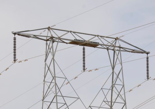
For years engineers have accepted that a direct lightning flash to an overhead line will cause flashovers at unprotected insulators. It is therefore desirable to divert lightning flashes to ground using overhead groundwires to protect insulation on transmission lines. But this is generally not done in the case of distribution lines that typically have critical flashover voltage levels of about 100 kV. Rather, parallel surge arresters protect expensive oil and paper insulation in transformers while the free ‘self-restoring’ air around insulators is left to fend for itself. Protective relays, reclosers, sectionalizers and fuses then complete the lightning protection of most distribution systems.

The original IEEE Standard 1410 (1997) and its later versions showed users how to determine the number of likely direct-stroke failures on distribution lines. This past revision left the same calculation in place but added an improvement in one step of the process. Every country, it seems, has a different relation from thunder to lightning. Therefore, instead of relying only on thunder observations, better estimates of lightning flash density are provided by NASA measurements of ‘optical transient density’ or, ideally, from reading out lightning location network data in those countries that have ground-based networks.
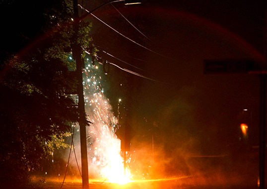
Engineering of lightning protection for distribution lines has focused mainly on ‘preventable’ flashovers associated with lightning flashes to the ground near the line. The electromagnetic field from such lightning events ‘illuminates’ the nearby line and ‘induces’ currents and voltages in the conductors – whether insulated or not. These induced currents and voltages scale to the rate of change of source current and are high amplitude, with short pulse widths of less than 3 microseconds (compared to typical lightning with a time to half value of 50 microseconds).

It is feasible in many countries to provide extra insulation that can withstand such short-duration voltage pulses. For example, by leaving insulator pins unbonded, utilities can take advantage of wooden cross-arm impulse insulation strength, adding about 235 kV of critical flashover voltage per meter of unbonded length. This in turn means that it also becomes possible to eliminate induced flashover problems simply by increasing the impulse insulation level of the line to above 300 kV (e.g. using a 105 kV CFO insulator in series with one meter of wood for a total of 340 kV).
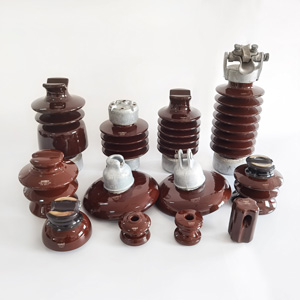
In some countries, experience with unbonded wooden cross-arms has been bad – not so much during the lightning season as during dry weather (including winter) followed by a period of wetting. This is because if salt and pollution have not been washed off ceramic insulators, leakage currents will flow across their surfaces and into the wood. Methods have been attempted to insert this leakage current into the wood but most eventually lead to charring and pole fires. Such fires can be mitigated by isolated bonding of three-phase lines, giving leakage currents a separate path to ground. In other cases, polymeric insulators or RTV silicone coatings have been applied.
In other countries, distribution systems are bonded at each insulator, perhaps through concrete or steel poles. For them, the best methodology to ‘keep CFO above 300 kV’ has not been easy. This led to studies of induced overvoltages using modern computational techniques, validated with results from experiments using triggered lightning.
It turned out (from advanced research in Italy, Switzerland, the U.S., Brazil and Japan) that there were three different ways to fully solve the electromagnetic problem and all agreed when implemented correctly. A traditional model, derived with an oversimplification of perfect ground, was correct too, but limited in value. The new models all showed how earth resistivity affects induced overvoltage. For example, the older ‘perfect ground’ model predicts one flashover per 100 km per year on a typical line with a CFO of about 130 kV. If the soil is good, but not perfect (e.g. at 100 ohm-meters) then 150 kV is needed for the same performance, all other factors being the same. If the soil is poor and grounding difficult (e.g. at 1000 ohm-meters) then a 250 kV CFO is needed.

The idea of adapting distribution line insulation levels to local soil conditions seems odd at first, especially since this induced voltage stress has little to do with the resistance of the interconnected neutral and its ground rods. It is therefore helpful to describe the effect with an ‘effective height’ of the distribution line over ground. For perfect ground, calculations can replace the ground with an image conductor, located as far below ground as the phase conductor is above ground. But if the ground is imperfect, the conductor and its image move farther away, making for a bigger area to harvest electromagnetic energy. The relationship of effective height to local soil resistivity is actually a nice simplification that originated in Australia.
The possibility of using arresters to improve lightning performance of distribution lines is also evaluated in the revised standard. One focus can be on relative role of only increased insulation length (whether polymeric or ceramic type) with the additional component count and complexity of a parallel arrester across a weaker insulator. There may be some bias in favor of longer insulators since these offer other reliability benefits.
One area where arresters should clearly play a role is in weak-link structures. Even if a utility has added wooden insulation or used longer polymeric insulators on most poles, there may still be those that have reduced insulation strength due to guy wires or other similar constructions. The general advice, “every grounded pole should have an arrester”, is generally good for resisting induced overvoltage, with one minor surprise. For lines with weak insulation (e.g. a CFO below 70 kV), arresters may actually degrade performance since they develop travelling waves that can cause problems elsewhere.

The P1410 standard has proven more comprehensive than previous editions, with appendices that provide the complex mathematics needed to solve the coupling and travelling wave problems in sufficient detail for the case of realistic soil. A computer on-line model was planned at time of the standard’s revision, similar to the FLASH program that accompanies the companion IEEE 1243 Guide for improving lightning performance of transmission lines.
International cooperation and debate resulted in a revision of the P1410 standard in a technically correct and also accessible way that gives simple yet balanced advice.