Whenever power supply companies plan a new overhead line they typically start with a set of ‘givens’. These include the tower types and conductor configurations typically used for that voltage class, the usual insulation applied for the line’s service environment, normal right-of-way requirements, etc. However, in developing Wintrack 10 years ago, its transmission line design of the future, the grid operator in Holland broke with this paradigm. Instead, engineers began not with any ‘givens’ but instead only with a set of objectives that had to be fulfilled. This approach allowed them a broad latitude in terms of possible design options.

As Europe’s most densely populated country, the Netherlands is a place where expanses of unused land are rare. In such an environment overhead transmission lines are not only unwelcome from a visual perspective but are also subject to close scrutiny in terms of how they might affect the health of those nearby. Indeed, based on epidemiological studies of people living near power lines in Sweden and the U.S., Dutch authorities advise avoiding long-term exposure of children to magnetic fields higher than 0.4 microTesla.
To meet such stringent requirements, power line corridors for traditional HV transmission projects would normally have to be some 300 m wide, meaning major obstacles given the dense infrastructure and public perception of overhead lines.
It was with these types of constraints in mind that engineers at TenneT, the country’s grid operator, embarked on an ambitious project in 2007 to apply a concept for new 380 kV lines based on steel poles and braced line post insulators in place of conventional lattice tower designs. Said Gerrit Boudewijn, TenneT’s Project Manger, “key considerations from the outset were low visual impact as well as reduced magnetic field in order to significantly reduce the line’s required corridor. And to achieve the first goal, we departed from past practices by bringing in the services of a team of architects.”
The engineering work to propose a groundbreaking design – christened Wintrack – that would meet all the required goals was then awarded in a public tender won by Kema Lab’s Energy & Sustainability Division. Peter Kolmeijer was the Account Manager who took charge of the work and subsequently became involved in almost every facet of Wintrack’s subsequent development. According to Kolmeijer, whose background was with a large European transmission line contractor, one of TenneT’s main requirements, apart from demonstrating competence in line design, was being able to work in conjunction with the appointed architects, something he remarks is still unusual when it comes to most power line projects.
Said Kolmeijer, “finding a pylon that would meet architectural considerations of being aesthetic and minimalistic and at the same time not be too costly and that could be sourced from local suppliers proved a challenge. For example, the bottom diameter could not be too ‘chunky’ while the top could not be too small to avoid it looking like a needle. Boudewijn explained that both structural steel and foundation costs tend to increase as footing dimensions of a transmission structure decrease. The goal was therefore to find some optimal balance between keeping the footing as small as possible to satisfy the criterion of minimalism while also respecting the fact that material and construction costs would be going up. “At the same time,” added Kolmeijer, “we had to ensure that bending under wind loading, especially for angle structures, would be within acceptable limits to keep them most pleasing to the eye.” He noted that while Dutch standards permit a lot of possible bending, Wintrack pylons are designed to have a top movement of at most 5.5 percent.
Hylco Hoekstra, a Technology Engineer at TenneT remarked that this maximum upper limit would represent an extreme case likely to occur only once every 500 years and that the maximum bending at the top might actually be only some 1.5 percent, encountered several times per year. Still, Hoekstra and Kolmeijer noted that even with this very slight deflection, there have already been sporadic comments from local communities that certain towers appear to be leaning.
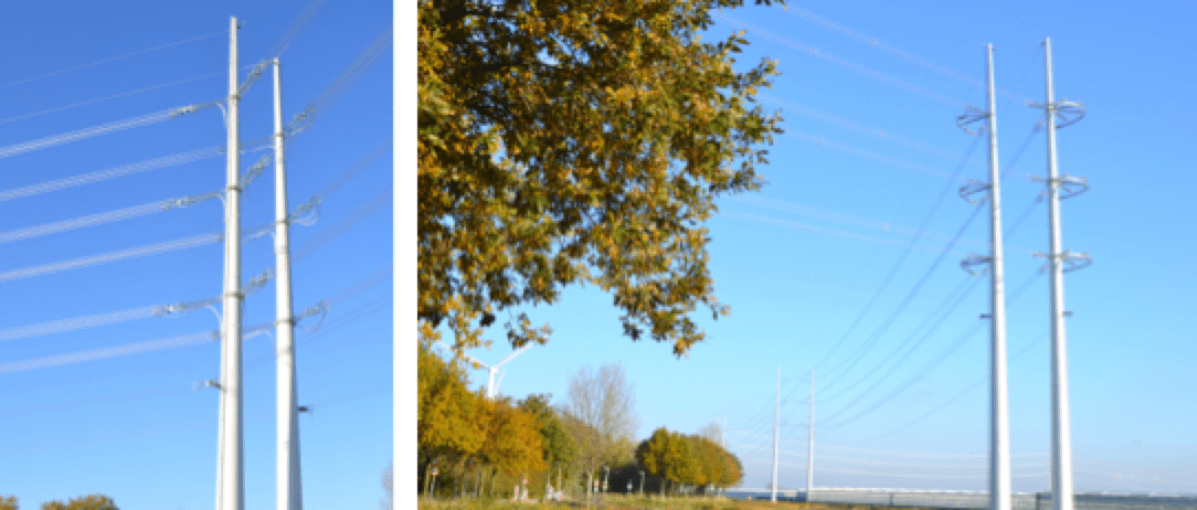
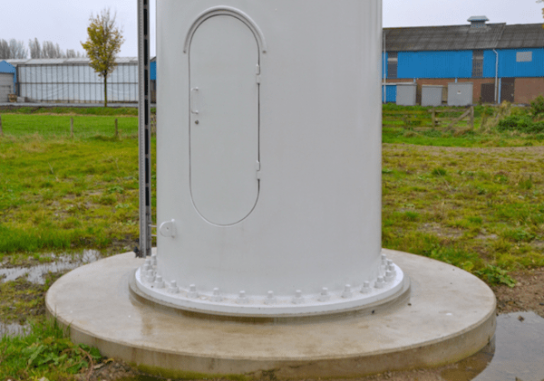
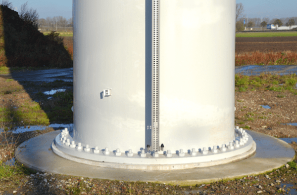
Another issue was maintenance requirements of the structures, which are painted papyrus white and equipped with a door allowing access to fix internal bolts to the concrete foundation during erection. These doors, according to Kolmeijer, are a good example of the important influence played by the architects. They were specially designed to fit flush with the structure’s walls to show only one smooth surface going upwards and present minimal added visual impact.
Kolmeijer explained that a number of alternatives to rolled steel pylons were considered at the outset, from epoxy to concrete. However he said that in the case of epoxy the costs would be too high and there would also be additional risk during overvoltage events in terms of the current’s path to earth. Concrete, while offering sufficient mechanical strength, was also rejected due to shielding and other issues. Observed Kolmeijer, “concrete is good in terms of withstanding pressure but you cannot pull or place too much cantilever force on it. The pulling strength of steel is definitely superior.”

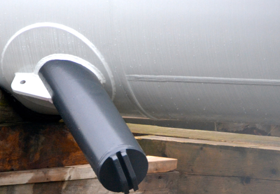
Yet another factor favoring steel in place of concrete was the placement of the black steel clips used to attach tension and line post insulators to the pylon. Said Hoekstra, “steel is advantageous in this regard since the location of these clips does not have to be determined in advance. They can be welded on wherever required. In the case of a concrete pole, their exact location would have to be known beforehand.”
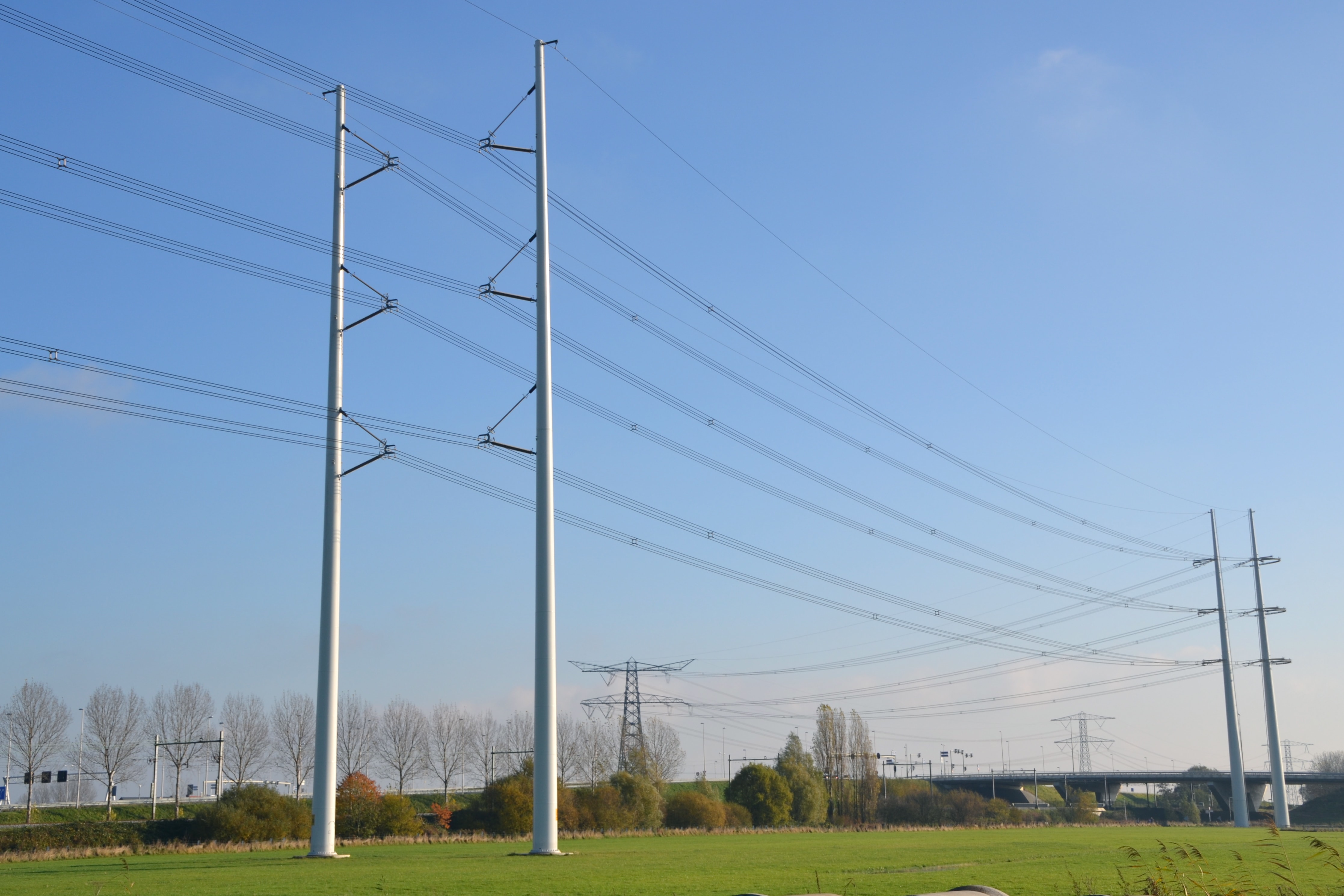
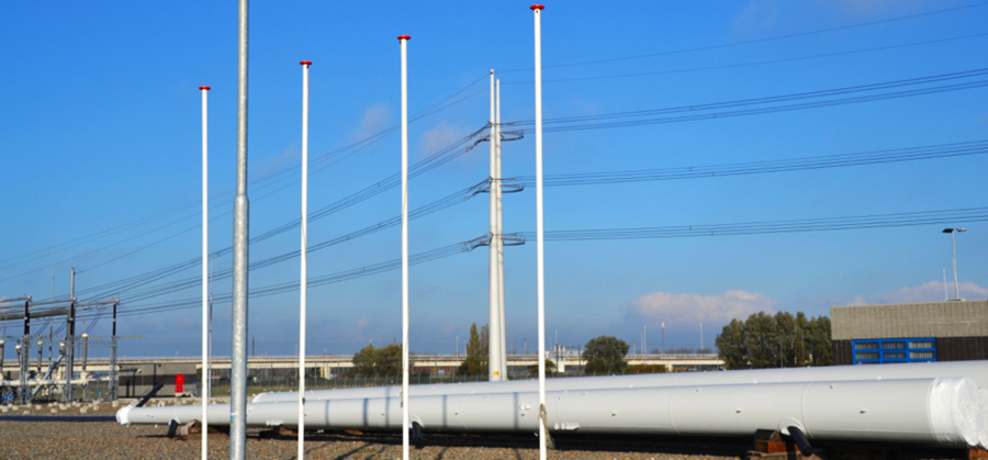
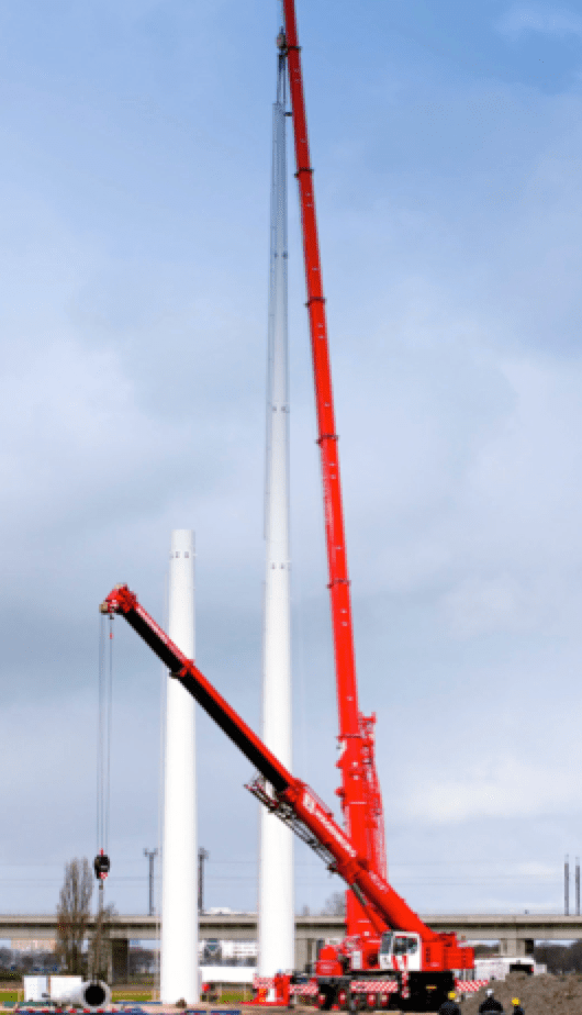
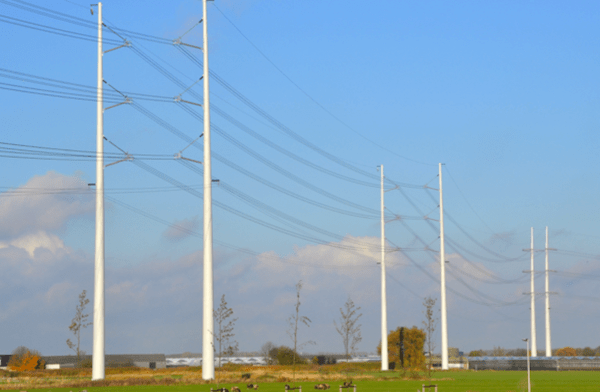
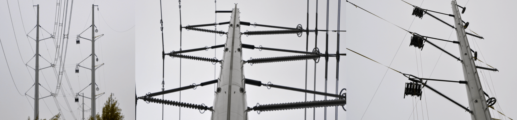
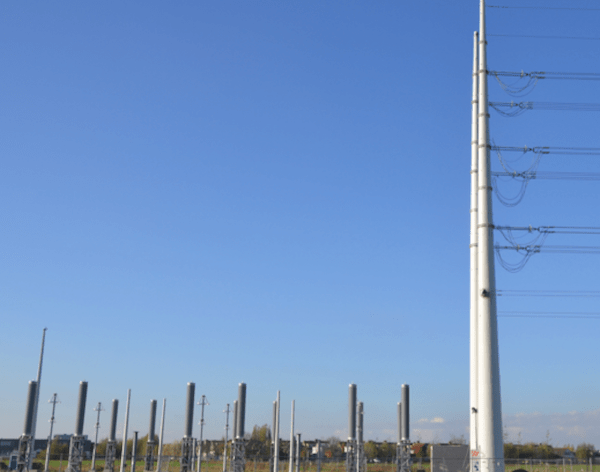
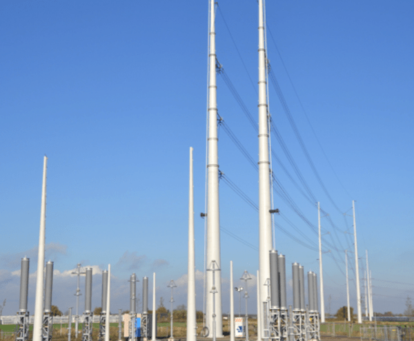
In the end, typical 380 kV Wintrack pylons stand 54 m high and consist of two sections attached with pre-stressed bolts. Special elevated structures for applications such as canal crossings rise 64 m and are made using three sections. This arrangement proved convenient since, at less than 28 tonnes per section and only up to 28 m in length, they could be delivered to site using standard means of transport. Typical spans for standard pylons are 350 and 400 m.
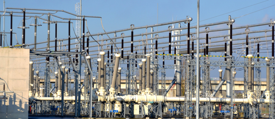
The centerpiece of the solution engineered to ensure very low overall electromagnetic field is the unique arrangement of conductors, each AAAC type and 620 mm in cross section. The idea was to bring these as close together as possible, while respecting minimum clearances, so as to allow their individual magnetic fields to offset one another. Testing and verification of the RIV and corona performance of the proposed configuration was conducted on a mock-up line set up at KEMA in 2009.
Another key element of the Wintrack design revolved around selection of insulators, which are all silicone rubber composite type. According to Hoekstra, this choice was made in spite of the fact that, apart from some early use in Holland at 150 kV during the 1980s, there has been comparatively little overall service experience with this insulator technology.
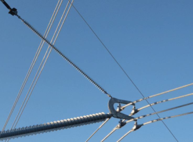
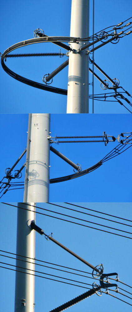
Kolmeijer reported that engineers first looked at equipping the new steel pylons with horizontal cross-arms but adds that this was quickly rejected from the standpoint of aesthetics since it would not have met the criterion of minimalism. Instead, suspension towers along straight sections of the line employ a braced line post design with the post insulators having a core diameter of 100 mm while the brace insulators are somewhat less in size.
When it came to angle towers, Kolmeijer said that the idea of an inverted brace was considered initially but eventually rejected. “Such solution” he explained, “would probably not have been good for maintenance purposes and also not ideal for load balancing on the two insulators. As a result, we decided to go with horizontal tension insulators for these applications.”
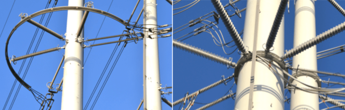
“A key consideration when it came to all these configurations,” said Hoekstra, “was on highly effective grading to ensure that the maximum field stress along the insulator would always be less than 2.5 kV/cm, a figure even lower than the 4.1 mm/kV recommended by EPRI in the U.S. This meant a great deal of shielding and therefore required a double grading ring designed by the insulator supplier.” Hoekstra explained that this design criterion was intended to ensure the longest possible service life with minimal risk of erosion of the housing due to corona.

Kolmeijer also pointed out that the Wintrack design, while quite new, is still evolving in terms of its various structural components. For example, the very first three towers, commissioned in 2009, featured tension and jumper standoff insulators connected directly to support rings inside the pylon. These rings assist the tower to withstand the insulator pulling force of some 70 kN. While such a solution offered minimal incremental visual impact, it created problems for the pylon contractor who found it more difficult to carry out zinc surface treatment of the ring given the structure’s confined internal space. “The external support ring solution is an acceptable compromise for now given the tight deadlines to complete the project,” noted Kolmeijer.
Another key requirement of the new line project was mixed-use capability of each pylon, a growing requirement of transmission structures worldwide. Said Kolmeijier, “the initial tender by TenneT specifically stated that whatever line concept was proposed would have to support not only two circuits of 380 kV with less than 1000A per circuit but also be capable of carrying two 150 kV circuits having more than 1000A per circuit.” He went on to explain that the idea of using a single pole to support two 380 kV circuits was rejected from the outset since it would not have allowed the minimum 5.5 to 6 m safe working distance if maintenance was being carried out on one circuit. That would have meant shutting both circuits in such cases – an unacceptable solution from the availability point of view. Therefore, mixed-use of certain Wintrack structures sees sections of the new line carrying 380 kV on one side and 150 kV on the other.
The installation of conductor on these mixed-use structures was another example of what Kolmeijer referred to as learning catching up with development. “There were problems during stringing due to the cantilever force from wheels being too great for the insulator configuration,” he explained. “So a temporary solution was to connect them to the adjoining tower for added support. Once the first three Wintrack towers had been completed in 2009,” he continued, “whenever we came up with new techniques or problems of this sort, we pulled in TenneT maintenance people so that they could be part of risk assessment for future line maintenance. These involved issues such as how best to ground the system as well as for processes such as repairing conductors and overhead ground wire, replacing insulators and inspecting suspension clamps.” Moreover, since Wintrack pylons do not offer any convenient place for maintenance workers to find support during such work, a novel rail access system was installed on every tower.
Another unique aspect of the new Wintrack line from Bleiswijk substation is that for environmental reasons it is was designed to include a 10 km section of cable. According to Kolmeijer, this combination of overhead line and cable will be a first for TenneT at 380 kV and, given the lengths involved, served as a test case for future similar installations.
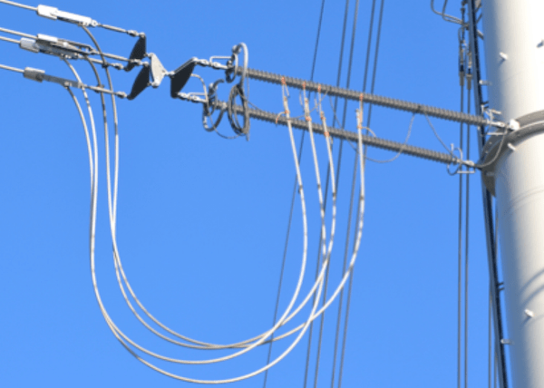
A good example of Kolmeijer’s comment that Wintrack is so novel that new construction and maintenance processes have to catch up is how unconnected conductor assemblies were left once workers departed at the end of the day. During the final weeks of construction, loose jumper ends had their weight supported by the top section of one of the two tension insulators. Kolmeijer glanced up at this arrangement and remarks that it is clearly not ideal and that better techniques will probably have to be considered.
Looking back on all that was involved in the new Wintrack project design, Kolmeijer said that arriving at the end result involved a lengthy process with some 40-50 different ideas proposed and evaluated. He also noted that the last 380 kV overhead line in Holland, built in 1995 using standard lattice towers, served as a valuable reference in terms of the relative engineering, scale and cost – all the more so since it was at the same voltage and had the same 4000A capacity. Still, Boudewijn pointed out that public concern about the possible health effects of magnetic fields made finding an entirely new solution mandatory and was in fact the critical factor in the whole development process. “The target of a maximum exposure of 0. 4 µT over a year really made the business case for us,” he emphasized. “Without such a constraint, interest from top management in developing such an innovative design would likely have been less.”
Said TenneT’s Hoekstra, “in the end, Wintrack’s cost per km was about 1½ times higher than would be required for one of our traditional lines. But in this case and a growing number of such cases in the future the classical design was really not an alternative. So it makes little sense to compare the two.” At the same time, he reported that public discussion of the new line has shown only positive reaction and that the affected community felt it has succeeded in its goal of integrating into their environment.
The new Wintrack design now forms the basis for future overhead line projects in Holland. For example, Hoekstra reported that another transmission line with this same concept would go up in the north of the country while two other 380 kV lines were also in review. Said Hoekstra, “for those newer lines, two circuits will not be sufficient so we are in the detailed engineering phase of a four circuit design.” Hoekstra also noted that ice and snow loading in northern Holland would probably mean that insulators on those lines will require higher mechanical strength and have core rod diameters of about 120 mm compared to the 100 mm for line posts used in the project to Bleiswijk Substation.