Increasing demand for electricity driven by urbanization, digitalization and the ongoing energy transition pose new challenges to the power supply industry. TSOs these days must deliver more energy with higher reliability while also seeking ideal technical efficiency, reduced carbon footprint and cost optimization.
One of the primary drivers of transmission line cost is acquisition and management of the Right-of-Way (ROW), especially in densely populated or environmentally sensitive areas. Traditional structures based on steel cross-arms with suspension strings require relatively wide lateral spans due to allowance for conductor swing. This increases ROW width as well as costs associated with land acquisition, environmental permits and project execution time.
Alternative solutions that reduce ROW width without compromising electrical or mechanical performance are therefore more and more attractive. One such solution consists of using insulated cross-arms (ICAs) to replace steel cross-arms and suspension strings. This allows for more compact conductor attachment with several advantages.
This edited contribution to INMR by D. H. Gueratto and other experts at PPC Insulators, A. de Pádua of Versátil Engenharia de Torres, and T. M. Santos at Connect Sistemas de Energia in Brazil is based on a case where the steel cross-arms on a transmission line with 14-unit glass insulator strings were replaced by ICAs made from porcelain longrods and solid core post insulators. Their analysis includes mechanical aspects, electrical performance, impact on project cost and environmental considerations.
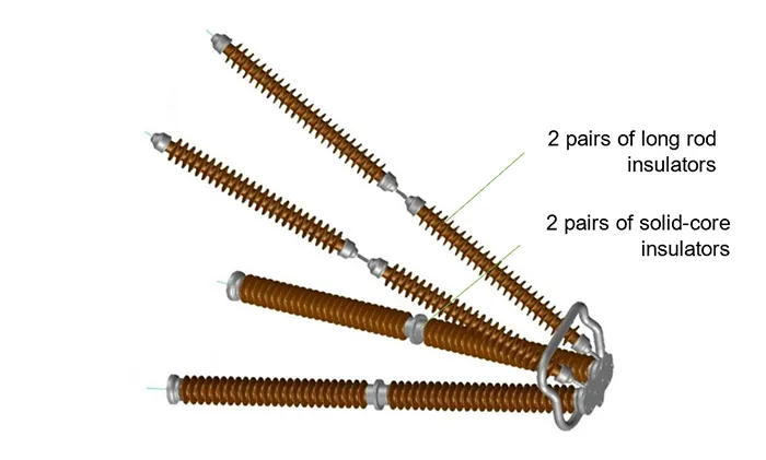
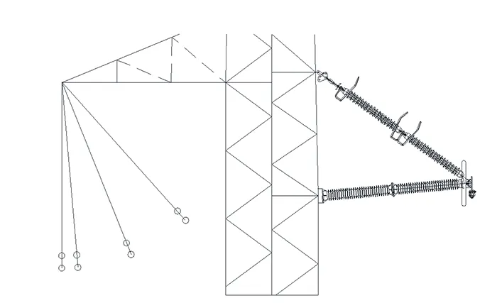
Insulated cross-arms represent a structural alternative to conventional arrangements of steel cross-arms with suspended insulator strings. One of the feasible configurations employs two sets of long rod insulators working in tension and two sets of post insulators operating in compression, as in Fig. 1. This set-up enables optimum utilization of each insulator while also leveraging porcelain’s inherent durability as well as reliable electrical and mechanical performance. This approach allows for a significant reduction in dynamic complexity and physical dimensions of structures, contributing to narrowing a transmission line’s required ROW.
In Brazil, design of transmission lines must comply with a set of robust standards, including:
• Brazilian National Standards such as NBR 5422 (Overhead Transmission Line Design) and NBR 15123 (Insulators for overhead lines above 1000 V – Insulator assemblies for AC systems);
• regulations from the Brazilian Electricity Regulatory Agency that, based on 6 auxiliary modules, establish the structural framework of transmission line roles;
• grid procedures from the National System Operator that provide operational and design guidelines, such as Submodule 2.4, which establish minimum requirements for overhead transmission lines;
• technical specifications from individual utilities and transmission companies, which can supplement or reinforce national and international standards.
Application of insulated cross-arms is well established in countries such as India, Switzerland, China and South Africa where the concept has already proven itself effective under harsh weather as well as in urbanized environments. This experience has provided a solid foundation for the concept and encouraged its adoption as a strategy to reduce costs, mitigate environmental impact and simplify civil works in new transmission line projects.
Proposed Methodology
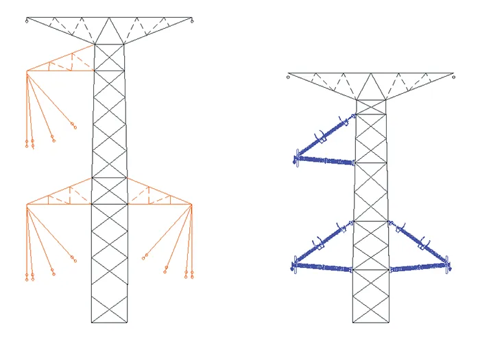
This study was conducted based on a transmission line project to be implemented between the States of Minas Gerais and Espírito Santo. The proposal consisted of replacing the traditional arrangement of latticed steel cross-arms with strings of glass discs by a system of insulated cross-arms composed of porcelain insulators. Fig. 2 compares the two configurations, maintaining same conductor height.
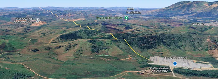
The new transmission line will connect SE Governador Valadares 6 and SE Verona Substations, across an area characterized mostly by mountainous terrain (see Fig. 3). The proposed line has a total length of 168 km and consist of 361 towers. It will operate at a nominal voltage of 230 kV and nominal current of 930 A, corresponding to a power rating of 370 MVA. The line uses CAL 1120 conductors with a cross-sectional area of 1.158 kcmil, arranged in a three-phase, single-circuit configuration.
Among the line’s different tower types, 187 are guyed, 35 are self-supporting light suspension, 36 are special self-supporting light suspension, 50 are self-supporting heavy suspension, and the remaining 53 include structures such as mid-span anchor, terminal anchor, transposition, and crossing towers.

Four tower types based on using insulated cross-arms were developed, each corresponding to a specific application within the line. Together, these would account for 308 of the project‘s 361 structures. To allow fair comparison between alternative solutions, the same tower allocation, mechanical loads and electrical insulation coordination used in the original design were maintained.
Structural modelling and performance analysis were conducted using the TOWER software from Power Line Systems/Bentley Systems – a popular tool for transmission line structure simulation. The models considered:
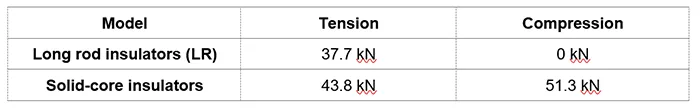
• tensile and compressive loads at conductor anchoring points (see Table 1);
• environmental and operating conditions;
• hypotheses for wind, temperature, conductor breakage, construction, and assembly;
• tower geometry; and
• minimum conductor ground clearance.
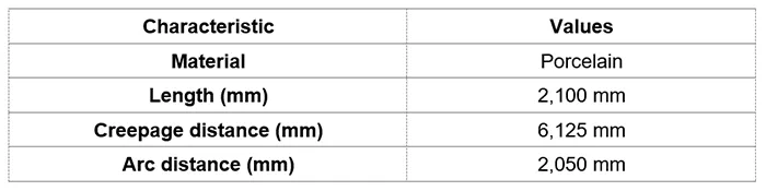
Insulator characteristics were established in accordance with requirements in ABNT NBR-6939 (Brazil’s Insulation Coordination Standard), summarized in Table 2

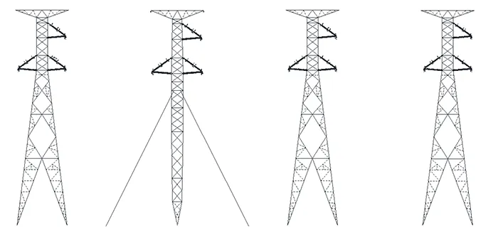
The specific details of each resulting structure are described below and the design is shown in Fig. 4.
PPCEL Towers
The “PPC Estaiada Leve” (PPCEL) is a guyed single-pole light suspension tower used on single circuit transmission lines with one conductor per phase. It is designed to withstand deflection angles of up to 1° and wind spans ranging between 550-520 m. Weight spans without wind range from 700 to 165 m for conductors and from 750 to 165 m for shield wires. Under wind loading, weight spans vary from 875 to 50 m for conductors and from 938 to 50 m for shield wires. Usable structure height varies from 19.5 to 39.0 m.
PPCSL Towers
The “PPC Suspensão Leve” (PPCSL) is a self-supporting light suspension tower, also configured for a single circuit and one conductor per phase. It supports deflection angles of up to 1° and wind spans between 550 and 520 m. Weight spans without wind vary from 700 to 165 m for conductors and from 750 to 165 m for shield wires. Under wind loading, weight spans for conductors are from 875 to 50 m and from 938 to 50 m for shield wires.
Height of the lower cross-arm varies from 13.5 to 42.0 m.
PPCSL-E Towers
The “PPC Suspensão Leve Especial” (PPCSL-E) is a special version of the PPCSL (self-supporting light suspension), also designed for a single circuit and one conductor per phase. It is intended for use at 0° deflection angles and average wind span of 480 m. Weight spans without wind range from 675 to 165 m for both conductors and shield wires. Under wind loading, spans vary from 900 to 50 m. Height of the lower cross-arm ranges from 13.5 to 42.0 m.
PPCSP Towers
The “PPC Suspensão Pesada” (PPCSP) is a self-supporting heavy suspension tower, capable of supporting a single circuit and one conductor per phase. It withstands deflection angles of up to 5° and wind spans from 700 to 530 m. Weight spans without wind vary from 1000 to 210 m for conductors and from 1050 to 210 m for shield wires. With wind loading, weight spans range from 1250 to 63 m for conductors and from 1313 to 63 m for shield wires. Height of the lower cross-arm ranges from 13.5 to 42.0 m.
Calculations & Discussion
A. ROW Width
Determination of ROW width (L) was based on a mechanical calculation that considers geometric and operational variables of the transmission line. The formula is:
L = 2 · [ b + (fa + Lstring) · sin β + (Lbundle/2) · cos β + D₁]
where:
parameter b represents the horizontal distance from the tower axis to the outermost conductor;
fₐ corresponds to the conductor sag for a 500-meter span under a wind load of 80 kgf/m²;
Lstring denotes length of the insulator string;
while Lbundle indicates the distance between sub conductors, which is zero in this case.
β represents the swing angle of the insulator string.
Finally, D₁ is the minimum safety clearance, calculated as the maximum electrical voltage divided by 150 kV/m, with a minimum value of 0.50 m.
The adopted values for the project under studt were as follows:
b = 3.24 m, Lstring = 0.20 m, Lbungle = 0.00 m, fₐ = 20.55 m, β = 34.58°, Vu = 242 kV, resulting in D₁ = 1.70 m.
Applying these parameters to the equation yields:
L = 2 · [ 3.24 + (20.55 + 0.20) · sin(34.58°) + 0 · cos(34.58°) + 1.70] = 33.60 m
For design purposes, a value of L = 34 m was adopted, corresponding to 17 m on each side of the transmission line axis. This width meets minimum safety requirements for mechanical and electrical clearances. Compared to the steel cross-arm configuration, this represents a 15% reduction in ROW width.
B. Reduced Tower Height
Adoption of insulated cross-arms introduced significant changes in how conductors are anchored to structures. By eliminating the suspended string, a more compact geometry becomes possible, reducing total tower height by 2.3 m. This has a positive impact on both the dynamic and static characteristics of the towers.
Reduced structural height decreased amount of steel required for tower manufacturing, contributing to a lighter structure and easier logistics. In addition, lowering the centre of gravity results in reduced loading on the foundations, allowing for shallower excavation and less concrete, ultimately lowering implementation costs and reducing environmental impact.
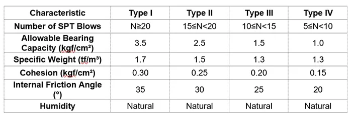
For example, to illustrate impact on foundations, Fig. 5 presents a comparison of guyed monopole tower foundations in soil type III, classified by the Standard Penetration Test (SPT). Table 3 shows the characteristics of different soil types.
Table 4 presents the quantities of materials used in the foundations for both alternatives. For the solution with a steel cross-arm, excavation volume amounts to 3.75 m³. Concrete volume is 3.94 m³ and reinforced steel (CA-50) consumption is 95 kg. By comparison, the solution with an insulated cross-arm sees excavation volume reduced by 20% (0.75 m³), concrete volume reduced by 19% (0.76 m³), and reinforced steel consumption down by 25% (24 kg).
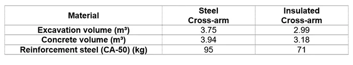

Steel and insulated crossarm, respectively.
Based on the original design, total steel weight of the modified structures is reduced by 10% (142,050 kg), concrete volume by 11% (79 m³) and excavation volume by 11% (75 m³). Total weight of guy wires for guyed monopole towers is reduced by 12% (2,549 kg).

Electrical Enhancement
Lightning strike is one of the main causes of transmission line tripping. The new conductor anchoring configuration increases the level of protection against lightning strikes provided by shield wire.
Transmission line performance was evaluated using two key indicators: number of outages due to direct lightning strike, and number of outages due to indirect lightning strike (backflashovers).
The acceptable thresholds are specified in ONS Submodule 2.4, item 7.5.4, based on IEEE Std 1243:
• ≤ 0.01 outages/100 km/year due to shielding failure;
• ≤ 2 outages/100 km/year due to indirect lightning.
The calculations were performed using FLASH software (version 1.6), considering the predominant tower configuration. The new configuration results in:
• Shielding failures: 0
• Back flashovers: 1.04
• Total annual outage rate: 1.04/100 km
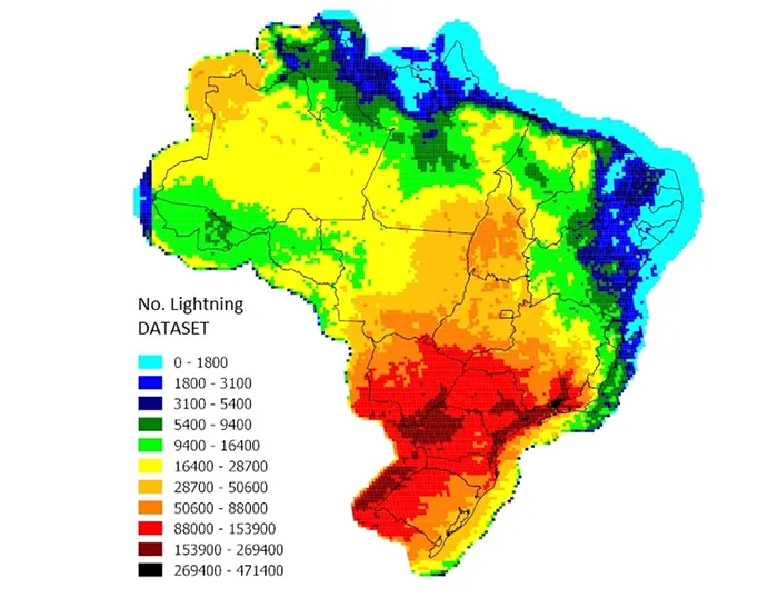
Both configurations exhibit effective shielding against direct lightning, with zero shielding failures. However, the insulated cross-arm configuration demonstrates better performance with regards to outages caused by atmospheric discharges, with a 26% lower rate. This improvement highlights the increased protection offered by more compact geometry and better electromagnetic coupling between conductors and shield wires. It should be noted that Brazil experiences a relatively high lightning strike density (see Fig. 6).
Moreover, this anchoring design mitigates risk of flashover and line tripping caused by wind-induced swing, i.e., conductor deviation from equilibrium configuration induced by wind. With this solution, distance between phase conductor and tower body remains constant. Fig. 7 compares alternative configurations.

Financial Analysis
Table 5 offers an analysis of capital expenditure (CAPEX) on this transmission line Project, contrasting latticed steel cross-arms with insulated cross-arms.
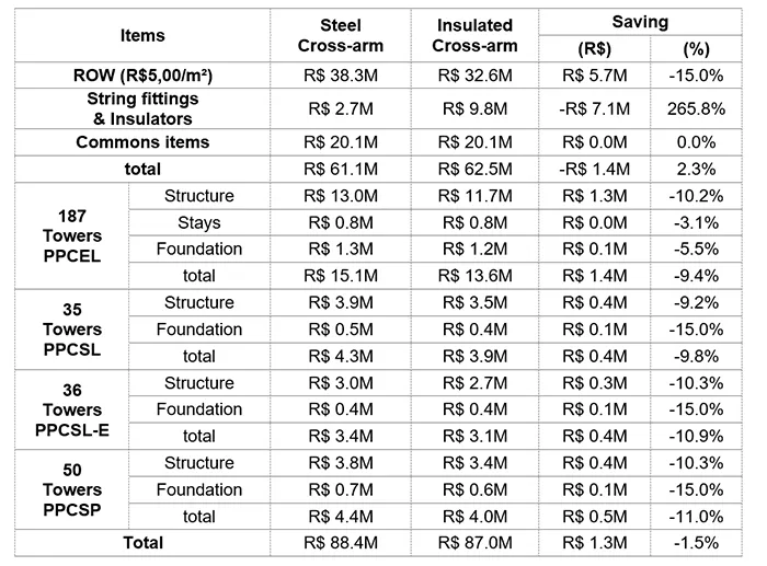
Investment saving in this specific case amounted to 1.5%, considering a land cost of R$5.00/m². If the project was in the State of São Paulo where average cost is R$12.00/m², savings would be 6.2%.
In addition to the positive impact on CAPEX, reducing ROW width by 4 m can also lower OPEX, since maintenance area decreases proportionally by about 15%. Considering the cost applied in this project (R$0.70/m²), this reduction could amount to R$705,600.

Conclusions
Comparative analysis demonstrates that replacing conventional steel cross-arms with insulated cross-arms on transmission line towers provides significant technical, economic, and environmental benefits.
1. Enabling a 15% reduction in ROW width, resulting in lower land acquisition cost and reduced maintenance area. The new configuration also allows for a 2.3 m reduction in tower height, leading to structural optimizations such as decreased excavation volume, concrete consumption and steel weight for both towers and foundations. Moreover, the reduction in required space facilitates uprating of existing transmission lines, enabling capacity increases without need for additional land acquisition.
2. Improving shielding effectiveness against atmospheric discharges, reducing lightning-induced outages by 26% compared to steel cross-arms. Another benefit is mitigating flashover and line tripping risks caused by wind-induced conductor swing, achieved through the fixed anchoring arrangement. This contributes to enhanced electrical power quality metrics.
3. Although cost of fittings and insulators increases, overall CAPEX reduction reaches 1.5% (R$1.3M) under the conditions studied, with potential savings up to 6.2% (R$8.4M) in regions with higher land costs.
In addition to the technical and financial benefits, this configuration offers environmental advantages by reduced usage of materials with high carbon footprints, such as steel, which emits approximately 2.3 ton of CO₂ per ton. Moreover, use of ceramic components contributes to sustainability since these materials exhibit service lives exceeding 50 years, resulting in significantly reduced carbon footprint over the system lifecycle.
These results confirm that insulated cross-arms represent a technically feasible, economically competitive, and environmentally advantageous alternative for transmission line projects, also aligning with modern requirements for cost efficiency and system reliability.
References
[1] M. Ahsan, M. N. R. B. Baharom, Z. Zainal, L. H. Mahmod, I. Ullah, M. F. M. Yousof, N. A. Mohd Jamail, M. S. Kamarudin, and R. A. Rahman, “Historical review of advancements in insulated cross-arm technology,” Energies, vol. 15, p. 8221, 2022. doi: 10.3390/en15218221.
[2] M. A. Alhazmi and P. Li, “Advancing resilient power systems through hierarchical restoration with renewable resources,” Scientific Reports, vol. 15, Art. no. 29755, Aug. 2025, doi: 10.1038/s41598-025-14992-z.
[3] R. A. Mahmoud, “Transmission line faults detection and classification using new tripping characteristics based on statistical coherence for current measurements,” Scientific Reports, vol. 15, p. 8487, 2025. doi: 10.1038/s41598-025-87577-5.
[4] M. D. Holloway and E. Holloway, Dictionary of Industrial Terminology, 2nd ed. Hoboken, NJ, USA: Wiley-Scrivener, Dec. 2020. ISBN: 978-1119364108
[5] Kimoto, I.; Kito, K.; Ueno, K. Insulator Crossarms for 345-KV EHV Transmission Line. IEEE Trans. Power Appar. Syst. 1971, PAS-90, 756–767.
[6] J. Voyatzakis Public Power Corp., Athens, Greece, “150 kV transmission lines on tapered steel poles supporting insulator crossarms in Greece”- 1989 International Conference on Overhead Line Design and Construction: Theory and Practice – IET
[7] ABNT – Associação Brasileira de Normas Técnicas, NBR 5422:2024 – Projeto de linhas aéreas de energia elétrica – Critérios técnicos, 2ª ed., Rio de Janeiro, Brazil, jan. 2024.
[8] ABNT – Associação Brasileira de Normas Técnicas, NBR 15123:2016 – Isoladores para linhas aéreas com tensões nominais acima de 1 000 V – Cadeias e arranjos de isoladores para sistemas de corrente alternada, Rio de Janeiro, Brazil, Mar. 2016.
[9] ANEEL – Agência Nacional de Energia Elétrica, Resolução Normativa nº 905, de 25 de fevereiro de 2020. Brasília: ANEEL, 2020. [Online]. Available: https://www2.aneel.gov.br/cedoc/ren2020905.html
[10] ONS – Operador Nacional do Sistema Elétrico, Procedimentos de Rede: Submódulo 2.4 – Requisitos mínimos para linhas de transmissão aéreas. Brasília, Brazil, [2010].
[11] Power Line Systems, Inc., TOWER – Transmission Tower Analysis and Design Software. [Software].
[12] Associação Brasileira de Normas Técnicas (ABNT), NBR 6939 – Coordenação de Isolamento para Sistemas Elétricos, Rio de Janeiro, Brazil, 2015.
[13] ABNT – Associação Brasileira de Normas Técnicas, NBR 6484: Sondagem de simples reconhecimento com SPT – Método de ensaio. Rio de Janeiro, Brazil, 2020.
[14] Y. Han et al., “Study on influencing factors of insulators flashover characteristics on the 110 kV true tower under the lightning impulse,” IEEE Access, vol. 6, pp. 66536–66544, 2018, doi: 10.1109/ACCESS.2018.2878274.
[15] IEEE Power Engineering Society, IEEE Guide for Improving the Lightning Performance of Transmission Lines, IEEE Std 1243-1997, 1997.
[16] Electricité de France (EDF) / CEPEL, FLASH – Lightning Performance Analysis Software, Version 1.6, 2012. [Software].
[17] W.J. Lou et al “An improved rigid rod method for wind-induced swing response prediction of heavily iced transmission lines,” Journal of Wind Engineering and Industrial Aerodynamics, vol. 235, 2023. doi: 10.1016/j.jweia.2023.105358.
[18] X. Song, S. Du, C. Deng, P. Shen, M. Xie, C. Zhao, C. Chen, and X. Liu, “Carbon emissions in China’s steel industry from a life cycle perspective: Carbon footprint insights,” Journal of Environmental Sciences, vol. 148, pp. 650–664, Feb. 2025, doi: https://doi.org/10.1016/j.jes.2023.04.027.