In an era when there is usually great public scrutiny of the construction of any new overhead electrical networks, the concept of compact line design has taken on a growing importance. Coinciding with and reinforcing this development has been the maturity of composite insulator technology in general and of composite line post insulators in particular. These types of insulators, with their unique combination of low weight and high mechanical strength, have greatly contributed to the range of possibilities available to designers of compact lines.
Among those countries where the building of compact transmission lines is now receiving great interest and attention is Israel. This past INMR from 2008 article discussed the factors which influenced decisions at the country’s major utility – Israel Electric (IE) – to prioritize the construction of compact lines and also reviews some of the associated advantages and disadvantages identified. In addition, certain related issues – such as electromagnetic fields – that were considered during the utility’s decision-making process are also presented.
The information for this article was contributed by engineers working at IE’s National Network Unit and also at its Electrical R&D Laboratory.

During the first half of the 1990s, the demand for electric power in Israel increased at an unusually high rate. That, in turn, required a rapid increase in the power transfer capabilities of the overhead network. New 161 kV and 400 kV lines had to be built and older ones either upgraded or partially refurbished. As typical in much of the developed world, obtaining permits for erecting new lines in Israel can be a lengthy and very difficult process. Moreover, because of its comparatively small land area and dense population, this process has become perhaps more demanding than almost anywhere else in the world. Ultimately, it was this unique combination of needs, constraints and opportunities (i.e. the emergence of composite insulator technology) which drove IE’s Network Division to begin looking seriously at increasing its selection and construction of compact line designs. According to the Deputy Manager of the Overhead Lines Dept., the first compact towers in Israel were built only a few years after IE’s first application of composite insulators. However, because of the utility’s still limited experience with this new insulator technology, it was decided that these compact towers should be equipped only with ceramic insulators.

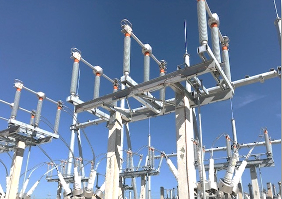
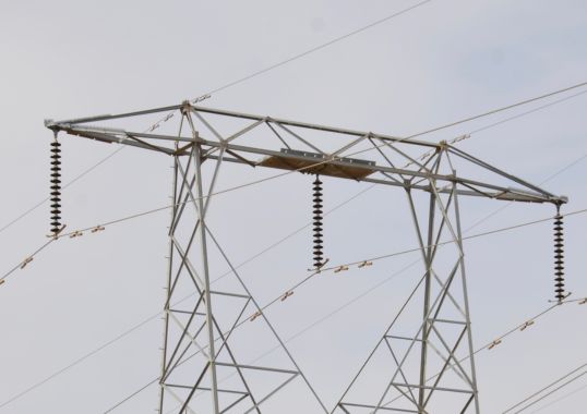
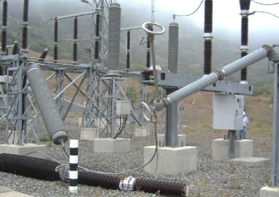
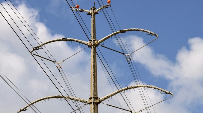
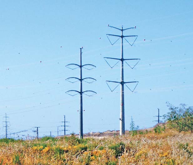
One of the first major design decisions taken by IE engineers in regard to compact lines was to use only vertical distribution of phases Subsequent design decisions included the use of tubular poles instead of conventional lattice towers and the use of V strings – both horizontal and vertical – in place of I strings. An important development promoting the trend toward more compact lines occurred in 1995 when IE decided to switch to exclusive use of silicone rubber (SR) composite insulators at all voltage levels on its network. It was also decided that, in the course of this changeover of technology, the same creepage length would be maintained as had been used in the past for porcelain.
The decision to use only composite type insulators actually contributed greatly to the compaction of lines because such insulators, not having the intermediate metallic fittings found along a ceramic string, allow for the same creepage distance but with a shorter overall insulator length. Then, in 1997, IE decided to formally recognize the superior pollution performance of SR insulators by adjusting their previous specifications so that such insulators could have 25 percent shorter creepage than had been required in the past for porcelain.
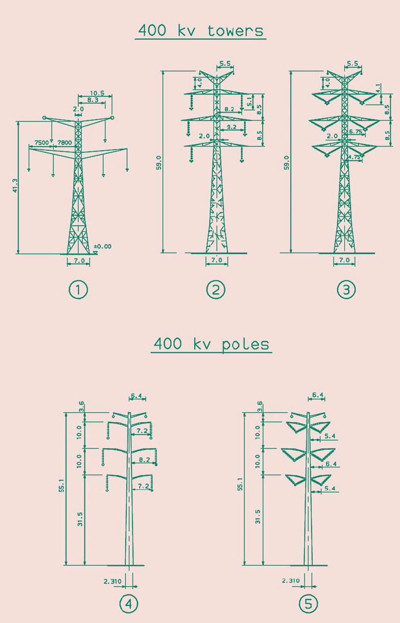
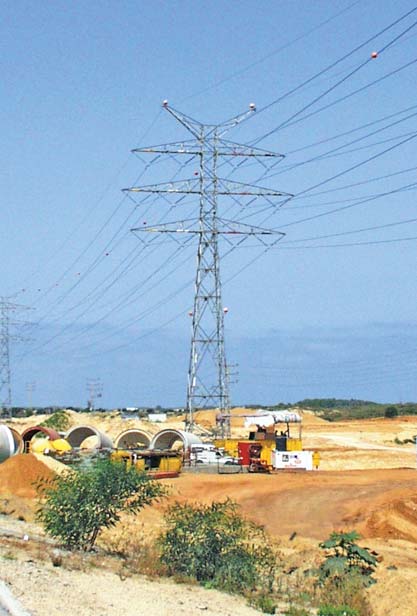
The significance of these decisions in terms of their impact on the possible reduction of the right-of-way corridor needed for lines can be seen from the dimensions of the towers shown in Figures 2 and 3. For example, in the case of 161 kV lines, the change from tower Model 1 to tower Model 2 allowed for a reduction of 3 meters on each side of the tower. For 400 kV, the change from tower Model 2 to tower Model 5 brought with it a possible reduction of 6 meters on either side. These reductions take into consideration not only the normal hanging position of the conductors but also their maximum swing arc due to lateral winds.

Based on operating experience over the years, IE’s Overhead Lines Dept. has developed the following summary of what they have found to be the major advantages and disadvantages associated with compact line construction:
Major Advantages of Compact Lines:
• Reduced corridors
• Reduced footprint of towers
• Possibility to increase the number of circuits installed per tower
• Reduced intensity of magnetic field outside right-of-way (RoW)
• Reduced audible noise outside RoW
Major Disadvantages of Compact Lines:
• Increased cost
• Poor lightning performance (i.e. shorter insulator strings mean a decrease of the protection angle of a line)
When analyzing the economics of compaction for both 161 and 400 kV lines, two different levels of cost increase were identified. In the case of lattice towers equipped with compact strings, the cost versus the basic normal construction typically increases by about 20 per cent. However, when specifying tubular poles with compact strings, this cost premium in relation to the basic design is more like 50 percent.
As a result and with consideration of all the positive and negative factors listed above, the policy adopted at IE for all construction of compact lines has now been defined as follows: In urban areas, all new lines will now be of compact design; while in open rural areas, new lines will continue to be built with conventional lattice towers. In addition, compact designs will be used whenever large amounts of energy have to be transferred along narrow corridors.
Right-of-Way Requirements
The common sense assumption is that, by switching to compact line designs that can be built along narrower corridors, the required RoW will diminish. However, in practice, IE continues to require from the Land Authority the same RoW for all new compact lines as it has traditionally established for standard line designs (i.e. 40 meters for 161 kV lines and 70 meters for 400 kV lines). The explanation for this seeming contradiction is based on several considerations: IE has a number of lines which consist of both compact and standard segments; there is an international trend to require ever lower values of the magnetic field along the borders of the RoW; and, doing so allows for a reserve permitting adding more circuits on the poles of the compact line at some future time. Because of this policy, any savings on land acquisition costs are obtained only in situations such as when several compact lines share the same corridor or when more than two circuits are installed on the same tower.
Towers with Original Designs
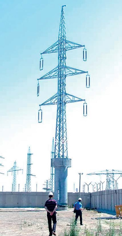
As already indicated, the high cost of tubular poles is seen as one of the main impediments to further extending the use compact line designs. Given this fact, one of the engineers with IE’s Overhead Lines Dept., proposed a solution involving a combination-style structure consisting of tubular base and lattice body and which offers a mix of the individual advantages of tubular and lattice towers, including: Being half the cost of an entirely tubular pole; requiring a reduced footprint versus purely lattice towers; offering superior protection against vandalism.
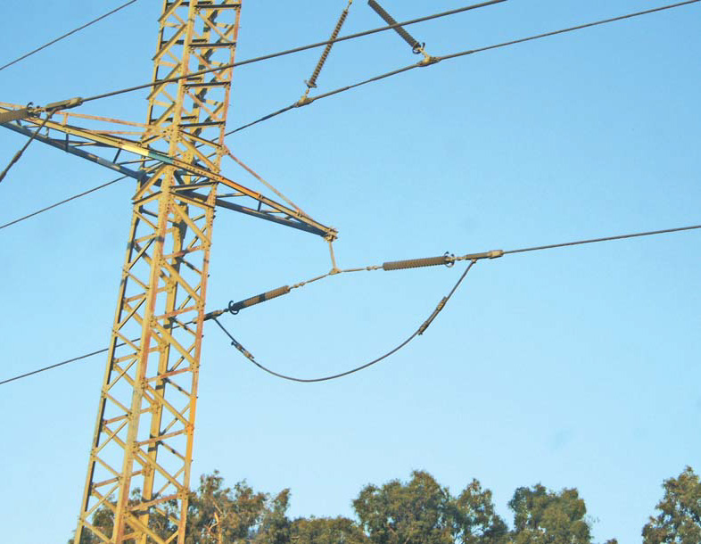
A second unique design concept introduced is a ‘combined string’ that aims to mix the features of suspension and tension strings. This string is comprised of tension insulators and the conductor is connected as on a tension tower. However, the tension on insulators is not transferred to the tower arm but instead passes from one insulator to the other along the line. Two main advantages are obtained in this way: raising the conductors higher above construction sites or roads; and the possibility to increase the rating of the line since the clearance of conductors can be maintained even if temperature increases. (Conductor temperature should normally not exceed 60° C but, with this special suspension configuration, it can be increased to as high as 100° C without any resulting problems due to the greater sag.)
Yet another technique identified to improve the power transfer capabilities of lines at IE has involved exchanging the type of conductors from the traditional ACSR (comprised of a steel core) to conductors made entirely of aluminum, e.g. AAAC type for transmission lines or AAC type for distribution lines. The use of an ACSR conductor is justified mainly under conditions of ice accumulation, galloping or large spans. However, since these conditions are not typical for the service environment in Israel, a change to these new types of conductors is already underway at IE. This changeover is expected to yield at least a 12 percent increase in the power transfer capacity of lines.
Influence of Magnetic Fields
Study of the issue of magnetic fields in overhead line design started at IE during the past decade. Until then, calculations of electric and magnetic fields were performed mainly for substations where personnel might spend many hours each day in close proximity to energized apparatus. The need to deal with magnetic fields from MV, HV and EHV lines arose in Israel only quite recently as the public became increasingly aware of potential risks related to long-term exposure. As in other developed countries, the suspicion grew that being exposed to even low magnetic fields could have adverse effects on health.

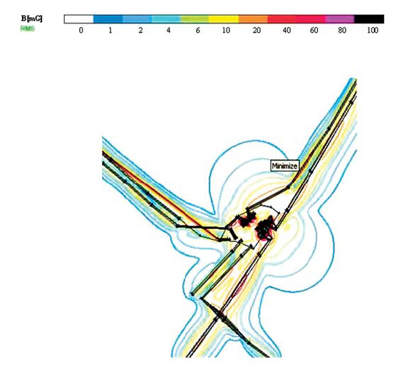
In this regard, IE has increasingly had to confront complaints, court actions and special requests to supply test results in order to obtain the necessary approvals for new line corridors. Most of this work related to measurement and calculation of magnetic fields around HV and EHV lines was performed at IE’s Electrical R&D Laboratory. In order to characterize the magnetic field of a line, measurements are performed at height of one meter above the ground along two axes perpendicular to the line – in the middle of the span and also under the tower.
The internationally accepted value for the maximum permissible magnetic field in areas where people spend long intervals of time is 1000 mG. This value was also adopted by Israel’s Ministry of the Environment and IE has had to comply with it. In practice, however, the values recorded along the borders of RoWs are actually much lower:
• In the case of maximum operational current along 161 kV lines built with standard towers, the magnetic field has been found to be 18 mG while for lines built with compact towers this value is only 8.5 mG.
• Along 400 kV lines, these respective values are 30 mG and 18 mG.
In order to comply with growing requirements for even more reduced magnetic fields, special solutions have been developed, including: using V strings on required spans in order to raise the conductors higher than normal and in this way to reduce the field at ground level;
phase transposition so as to offset the magnetic field produced of one circuit by the field of the circuit installed on the other side of the tower; installing supplementary towers, again in order to raise the conductors to a higher elevation than normal.
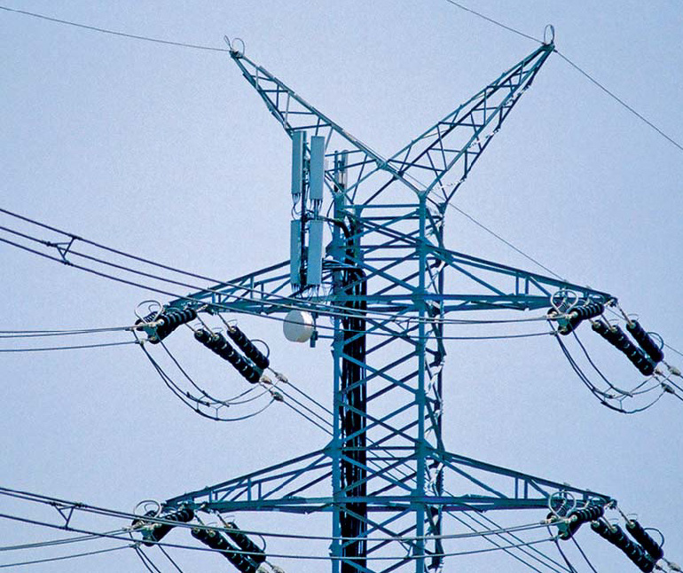
Another initiative taken at IE related to this issue was to permit installation of antennas for cellular communications on top of MV and HV towers. The Deputy Manager at the IE’s Electrical R&D Laboratory explained why their Department has chosen to perform such measurements in the field to supplement the computations made based on mathematical models. Actual measurements, he said, are useful not only to verify the accuracy of the model but also for detecting unknown sources of magnetic fields in the area. At the same time, he acknowledges that such measurements show the situation only in the particular location and at the specific time they were carried out. Mathematical computations, by contrast, permit the intensity of the magnetic field to be evaluated for different values of the current and at many different locations along the line. They are therefore indispensable at the design stage in order to obtain approval for construction of a new line.
Due to the sensitivity of this issue of electromagnetic field and the ongoing research being done on it, IE has decided to adopt a policy of “Prudent Avoidance”. According to this policy, IE aims to satisfy the requests of the public to reduce magnetic fields as much as possible and even below mandatory thresholds so long as the costs are reasonable and standard technical solutions can be used.

Major Conclusions
Compact lines are a valuable solution not only for smaller countries such as Israel, but indeed for any developed and densely-populated country where there is a need to transfer increasing amounts of energy through already allocated land corridors.
Compact lines and towers also offer the possibility for new and more effective solutions to reduce magnetic fields along the line, a sensitive and growing issue in many countries.