Swedish transmission and distribution overhead networks have historically relied on porcelain and glass cap & pin insulators, but the past decades have seen composite insulators introduced in selected applications across 50–400 kV, with varying outcomes.
This edited contribution to INMR by Claes Ahlrot, of E.ON Energidistribution, Dan Windmar of Svenska kraftnät and Milan Radosavljevic of Vattenfall Eldistribution compiles field experience at Swedish utilities including observed failure modes, inspection and maintenance practices, and resulting changes in purchasing specifications.
Sweden operates one of the world’s oldest high voltage power systems, with the first 220 kV lines built in the 1930s using porcelain insulators. Since then, the country’s 130 kV, 220 kV and 400 kV networks have all employed predominantly porcelain and glass cap & pin strings with good service experience. The latter remain the standard from 130 to 400 kV.
Composite insulators have seen limited use on Swedish overhead lines, though some have been installed for over more than 20 years, particularly at substations where composite apparatus types have been preferred for safety reasons during explosive failures. E.ON’s first composite long rod line installation occurred in 2014 while Vattenfalls’ s first composite insulator line was built in the mid 90s.
Swedish Environmental Context
Swedish operating conditions include wide temperature variation (i.e. from -40 to +35°C) and coastal areas along the North Sea experience salt pollution. Still, ESDD levels are generally low and pollution is typically classified as very light. Creepage design therefore commonly targets USCD ≈ 25 mm/kV (SCD 15 mm/kV).
Transmission line components are specified for 80 year expected service life, while substation equipment targets 40 years.
1. Network Overview: E.ON Energidistribution (EON)
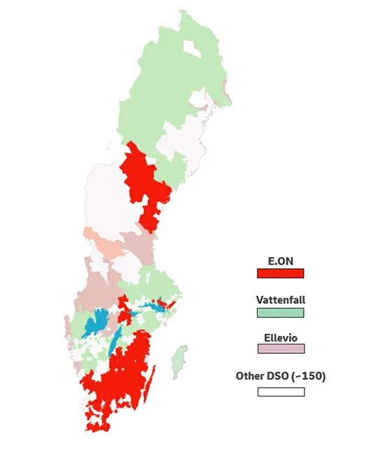
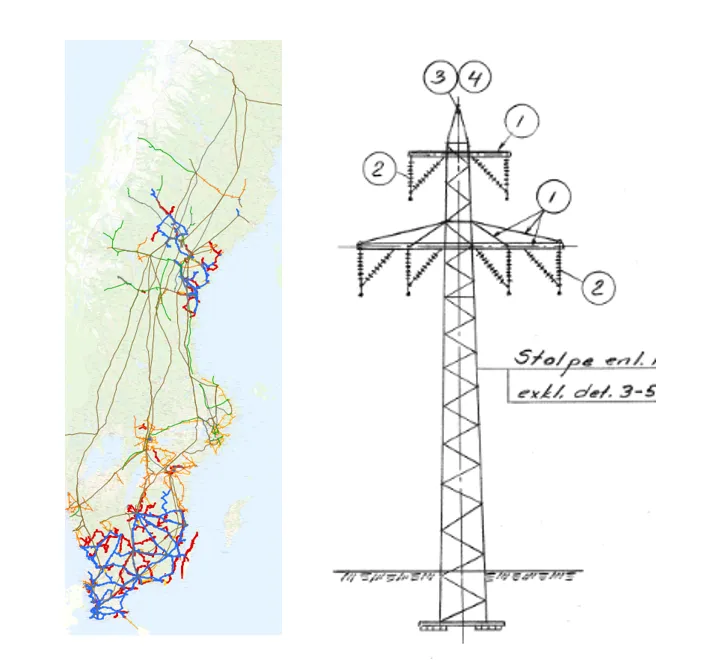
E.ON Energidistribution is one of Sweden’s major DSOs, operating both regional and local grids (see Fig. 1).
• Regional grid voltages: 45 kV, 55 kV, 70 kV and 130 kV;
• Local distribution: 10 kV and 20 kV, down to 0.4 kV;
• Total Network length: ~143,000 km, of which ~9,000 km is regional.
At lower voltages, composite line post insulators are common while at 145 kV, glass cap & pin is the standard. E.ON has also been using composite insulators at substations for safety considerations with no reports of faults.
2. Network Overview: Vattenfall Eldistribution (VA)
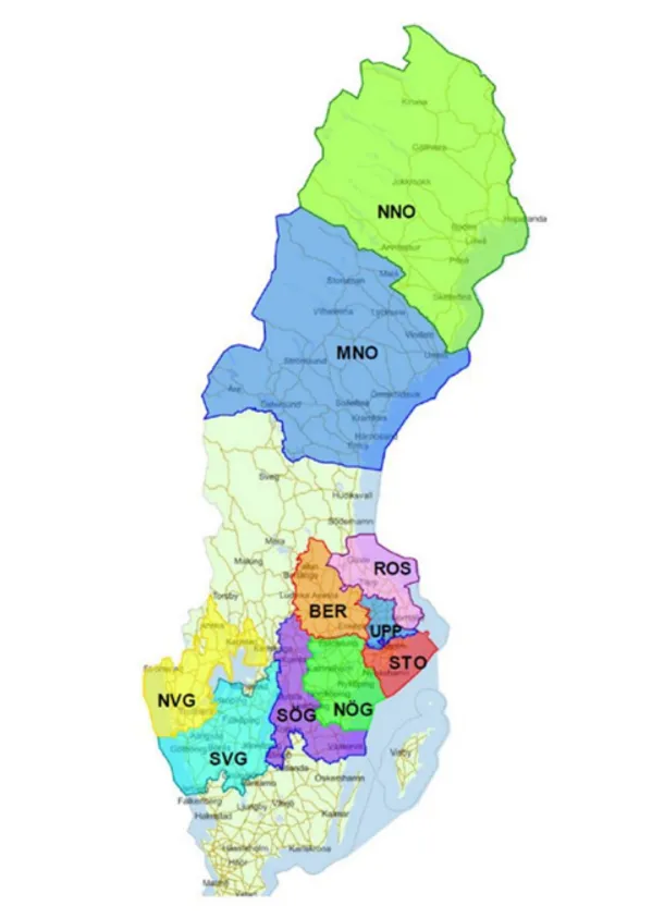
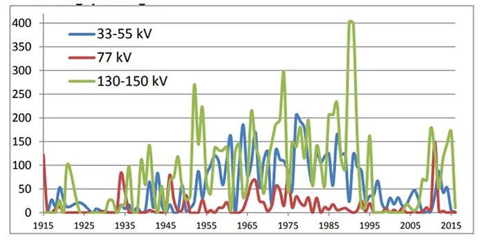
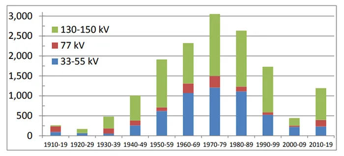
Vattenfall Eldistribution operates parts of the regional network (see Fig. 2), with 55 kV, 70 kV and 145 kV sub-transmission, and distribution levels down to 0.4 kV (see Fig. 3). Composite line insulators were introduced in the mid 90s during a period of 145 kV line expansion (Figs. 3 & 4). Historically, specifications were based on cap and pin strings without composite specific clauses.
3. Network Overview: Svenska kraftnät (SVK)
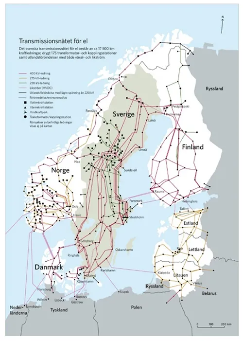
SVK is the Transmission System Operator (TSO) in Sweden and operates the grid at 220 and 420 kV. Today, the Swedish national grid at 220 kV and 420 kV consists of circa 17,500 km of transmission lines and ca 175 substations (see Fig. 5). In the coming 20 years, some 4800 km of transmission lines and 100 substations will be built and commissioned.

Observed Faults & Field Experience
1. E.ON Case Studies130 kV VKA–FLD (Coastal South)
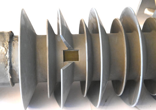
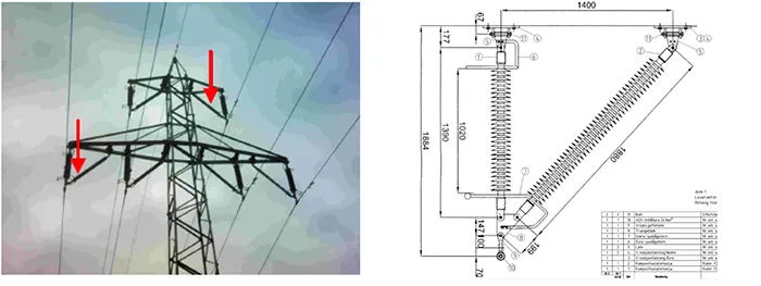
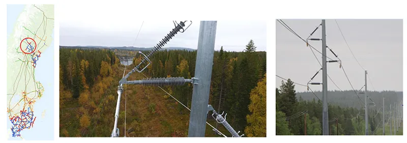
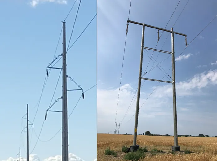
To uprate a former double 50 kV overhead line to a double 130 kV OHL, new beams with V shaped composite long rod insulators were installed in 2014 (see Figs. 6 & 7) along a corridor exposed to strong winds and salt spray (Figs. 8 & 9). The insulators were tested according to the former IEC 61109.
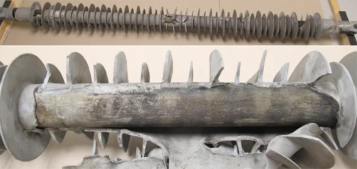
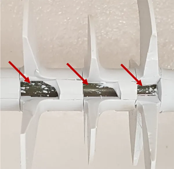
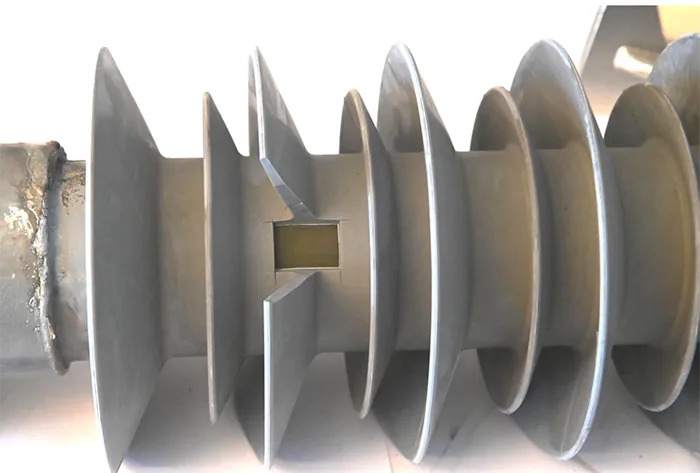
In 2016, two years after installation, failures occurred on both lines. Laboratory inspection of two failed units indicated a problem of weak adhesion between the FRP rod and the silicone housing (see Figs. 10 & 11). The failed insulators were replaced, and the lines were energized. Inspection showed raised temperature in several insulators in both lines. About 150 insulators were replaced; replacement batches underwent additional adhesion testing, and no further failures have been recorded.

Strömsund–Hoting (40/50 kV Uprated to 130 kV)
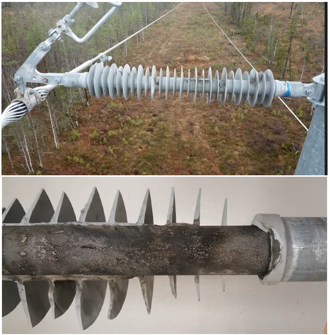
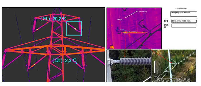
In 2014, wooden line post poles were replaced with tubular steel poles using V strings of composite long rod insulators for the uprating (see Figs. 12 to 14). The line’s route traverses mountain and forest terrain with low contamination. In 2017, a flashunder was detected on one insulator and the root cause was identified as weak adhesion between rod and housing (see Figs. 15 & 16). Infrared (IR) inspection was conducted along the entire line and several more silicone insulators were exchanged due to raised temperature and observed surface damage.
Additional 130 kV lines (2016, 2018)
Two 130 kV lines were equipped with composite insulators in southern Sweden (see Figs. 17 & 18). In addition to IEC 61109, adhesion focused tests were performed on delivery samples. All showed good adhesion.

Nysäter–Jenåsen 130 kV (2018)
The first batch pf samples failed during adhesion tests and a second batch failed as well. A third batch displayed some deviations but was nevertheless installed. No service failures have been reported to date (see Fig. 19).
2. Vattenfall Experience & Specification Updates
Vattenfall Eldistribution has not recorded major problems with installed composite post or line insulators. Still, considering incidents reported by other TSOs/DSOs, in 2023 VA updated its purchasing specification for composite line insulators (Doc: VTR05 18E), introducing additional FAT sample tests for each batch. Key item included are:
• maximum electric field (E field) allowed at end fittings (calculated); and
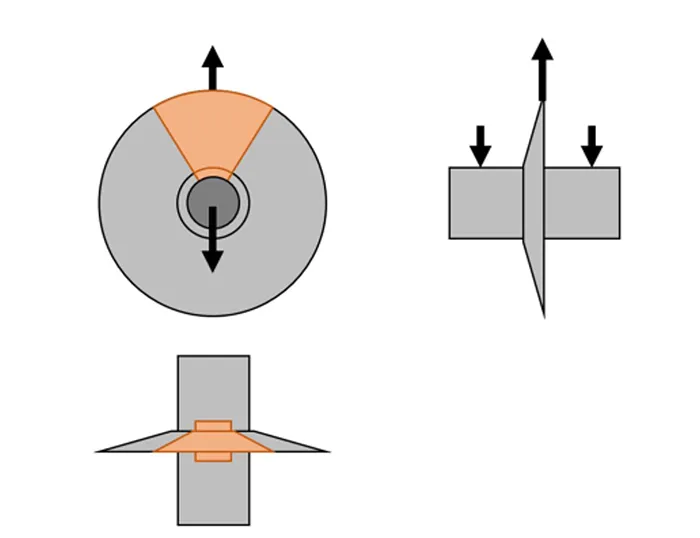
• pull off adhesion test on FAT samples to verify sheath to rod bonding (see Fig. 20).
Revised IEC 61109 (introduced Feb. 2025) now covers parts of VA’s specification, simplifying procurement and encouraging manufacturers to adopt these requested tests and procedures.
3. Svenska kraftnät (SVK) Experience
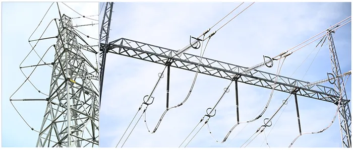
SVK installs glass cap & pin insulators for standard line work and composite types are used only for special structures such as transposition towers and portals (see Figs. 21 & 22).
RL6 S9 Failure
At the end of May 2022, Line RL6 S9 failed and could not be reconnected. After a few days of troubleshooting, a short-circuited composite insulator was discovered on Pole 21C, where the insulators were installed and commissioned in 2007. There are a total of 5 other composite insulators on this pole having the same design and age. The failed insulator was replaced with a similar one from the same manufacturer but of different design. The failed unit was then dissected to determine root cause of failure and the remaining insulators on that pole were inspected closely to assess their condition.
During this inspection, there were clear traces of discharge activity, and it was also discovered that the seals had started to leak. IR imaging also revealed that all insulators showed slightly elevated temperatures at their fittings. UV imaging confirmed that this heating did not originate from external corona, which was evidence that some discharge activity was taking place between housing and rod at the high voltage fitting.
When removed, an adhesion test (as has recently now been included in revised IEC standards), showed that the breaking force was far below the required value of at least 1.5 N/mm2. Moreover, the fracture surface was completely blank with no residual products from the sheath, i.e. it was a completely adhesive fracture. This was confirmation that the adhesion was deficient. Fig. 23 is an example of the poor bonding seen.
The root cause of the failure showed that it was a combination of poor adhesion between sheath and rod and too high E-field at the high-voltage armature, which created discharges at the interface.
Ramsele Substation
Low adhesion was detected on composite station support insulators at Ramsele Station. Dissection of 2 units with elevated temperatures revealed extensive damage under the silicone rubber. Discharges within the FRP core caused erosion of the epoxy, and the damaged core became conductive.

Inspection & Maintenance Strategies
1. E.ON
Following field incidents, E.ON evaluated:
• Visual Inspection was useful mainly for finding signs of external damage or for post fault assessment;
• PD and UV inspections were indicative in some cases, especially for corona;
• IR inspections (performed from the ground and using drones) were the most effective in terms of detecting poor adhesion and interface heating (see Figs. 24 & 25).
All OHLs with composite insulators are now inspected more frequently using drones and IR cameras.
2. Svenska kraftnät
Based on dissection and inspections, Svk recommends:
1. Installing electric field controlling rings on all composite line insulators;
2. Following up with IR/UV inspections to verify status;
3. Checking seals during de energized inspections (e.g. when installing grading rings);
4. Removing and dissecting selected insulators to verify seal integrity and sheath to rod adhesion as well as to assess potential rod/interface damage near the HV end fitting.
3. Vattenfall
No major service issues reported. Preventive focus lies on procurement controls (E field limitation, adhesion pull off testing) embedded in VTR05 18E and aligned with IEC 61109 (2025).
Purchasing Policy Implications
1. E.ON Energidistribution
• After 2018, E.ON adopted a stop in using composite line insulators at 130 kV citing limitations in IEC 61109 regarding adhesion testing;
• With the IEC 61109 update, E.ON is updating internal technical requirements (roll out planned this year);
• Until then, application of composite long rod insulators is being decided on a case by case at the project level.
• Glass cap & pin insulators will remain the main choice for OHL at higher voltage levels.
2. Svenska kraftnät
• Replace all damaged composite station support insulators and switch to porcelain supports;
• No composite line insulators are allowed on transmission lines, except for specific applications;
• If used, composite line insulators must comply with IEC 61109:2025, including limits on electric field.
3. Vattenfall Eldistribution
• No major problems have been observed in service;
• Purchasing specification VTR05 18E (2023) mandates E field limits and adhesion pull off tests during FAT, now already partly harmonized with IEC 61109 (2025).

Conclusions & Recommendations
Primary drivers of failure
Inadequate sheath to rod adhesion and high E field at HV end fittings, causing internal discharges and thermal anomalies that are detectable by IR inspection.
Inspection effectiveness
IR thermography (including drone based) is the most reliable screening tool observed. UV/PD inspection provide complementary evidence.
Procurement controls matter
Enforcing adhesion tests (e.g., pull off/peel), checks of seal integrity and E field design limits will help reduce risk.
Standardization helps
Adopting IEC 61109 (2025) and alignment of utility specifications to this are expected to improve manufacturing consistency and service reliability.
Policy divergence reflects experience
Field failures tend to restrict application of composite line insulators, while experience without failures tends to result in broader acceptance, but still with tightened specifications.
Ongoing needs
1. Robust, standardized adhesion and interface testing (easier and more reliable tests can be developed and several self-invented tests are now in use by different manufacturers);
2. Improved live (non outage) inspection methods; and
3. Clearer E field design criteria and guidance on application of grading rings.