While past years have seen the emphasis placed on reducing cost of substation insulation in respect to materials, insulators and apparatus, the focus has now shifted to different considerations: total cost of ownership (TCO) and life-cycle assessment (LCA). Moreover, TSOs and OEMs these days are verifying their supply chains to consider non-technical issues including CO2 footprint, factory working conditions and other such requirements.
Similarly, the substation insulation selection process going forward will have to comply with the latest chemical regulations as well as maintain a preference for green, non-hazardous and sustainable materials. Finally, the IEC has agreed to support the UN’s sustainable development goals when issuing standards. In parallel, more eco-friendly materials are being developed along with re-use and recycling methods that must adhere to the latest safety, health and environment (SHE) regulations.
This edited contribution to INMR by expert consultant Dr. Jens Seifert, prepared on behalf of Saver in Italy, explains how all these factors will impact the latest generation of composite hollow core insulators and GIS bushings.

Composite Hollow Insulators
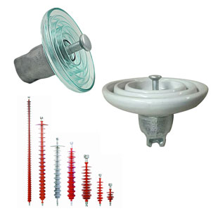
As stated in IEC 61462, hollow core composite insulators (HCIs) are among the key components of HV apparatus used at substations. They serve as housings that guarantee the required mechanical (i.e. bending, pressure, tightness) as well as electrical properties and protect against environmental stresses.
These are produced for AC and DC applications with special design approaches in each case and their range is specified within IEC 60815 (recently expanded to also offer insight regarding DC voltage stress), which provides guidance for best design in respect to polluted conditions.
So far, there are no specific characteristic or dimensional standards for HCIs, and it seems unlikely these will be realized in the future. The reason for this includes specific customer design requirements as well as historical product portfolios and specifications on the part of users, i.e. OEMs and TSOs. The resulting greater variety in designs needs to be handled through smart production and a logistics system that guarantees acceptable lead times.
A. Materials
Silicone rubber has been the state-of-the-art material used in HCI housings for decades. Nonetheless, its development has continued to progress with regards to performance, e.g., tracking and erosion, hydrophobicity and mechanical properties. Regarding SHE, for example, a key step has been taken with introduction of platinum (Pt) catalyzed curing systems for LSR and HTV processing technologies (i.e. injection molding and extrusion).
Pt catalyzed addition curing systems do not emit hazardous volatile substances, e.g. from former standard peroxidic curing agents based on C6 or C1. The latter will eventually disappear since ECHA/SVHC regulations will ban these step-by-step. The latest example is the SVHC candidate proposal of dicumyl peroxide (DCP) C1 agent. The different stages in the SVHC process include ‘information for users’, ‘proof of concentration below limit value (e.g. 0.1 % by weight)’, ‘approval of application’, and finally ‘complete ban’.
Regarding epoxy resin impregnation, a process is already in place for anhydrate hardeners where two chemicals have now been replaced. In the ECR glass fiber roving production industry, there is greater consolidation since SHE rules increasingly request formal approvals from local agencies, resulting in increased effort and material costs. For HCI manufacturers, this means additional burden to renew the qualification process with related time and added costs once required changes in raw material are announced by suppliers.
This is not ideal since it hinders quality suppliers that comply with European Union standards while unintentionally benefitting suppliers in countries that do not comply yet still supply the EU market. Given the recent changes in how OEMs and TSOs qualify suppliers, this situation may end of being considered during the supply chain process.

B. Technology Trends
Regarding processing technologies there are clear trends: Injection molding using LSR and HTV materials will account for the bulk of total production with mold-based processes resulting in equivalent performance for both LSR and HTV silicone rubbers. Extrusion technologies (using mainly HTV rubber) and 3D printing (with both LSR and HTV) will be applied to manufacture insulators of very large size or having special conical/barrel shapes as well as for direct application of a silicone housing to dry-type cable terminations.
C. Alternative Gases
Although SF6 is a highly efficient insulation and switching medium, the latest REACH decisions will see the gas banned by 2036 in two steps: 145 kV by 2032; >145 kV by 2036). The search for alternative gases started in the 1990s resulting in recognition that replacement media also have high greenhouse potential. Still, these are lower than SF6 especially if diluted with carrier media such as N2, CO2 or O2.
This issue is important for insulation applications such as gas-insulated bushings, and instrument transformers as well as for switching applications. Gas mixtures based on fluoronitrile (FN) or fluoroketone (FK) are available and proven by respective testing with peak breakdown strength of 55…70 kV/cm (vs. 80 kV/cm for pure SF6). These alternative gases require special machines for filling/re-filling that differ from those used for SF6. As an alternative, use of dry ‘technical’ air is being applied by some OEMs. One disadvantage is relatively low breakdown strength (30 kV/cm peak), meaning pressure must be increased while insulation distances/diameters will typically increase by at least one class.
The switching function in related circuit breakers is handled by vacuum breaker tubes, a concept that has a fully ‘green’ and economical footprint regarding insulation and vacuum breakers. For HCIs used in ‘dry air/clean air’ applications, special measures must be taken during design to mitigate CO2 and O2 diffusion processes.
D. Life Cycle Assessment (LCA)
Over the past years, LCAs for HCIs have been performed either as part of EU funded projects or supported by large OEMs and TSOs. Results have shown consensus, i.e.:
• Total service life is equivalent to that of porcelain;
• Recycling and re-use characteristics are similar to those offered by ceramic insulators;
• CO2 footprint is better than for conventional insulators while emission of fine dust is much lower for polymeric materials;
• Performance is better compared to porcelain, especially for HVDC applications and/or under polluted service conditions;
• Aspects such as hardening substations against threat of terrorism favor their use at substations, especially in the United States. A relevant IEEE Task Force was established in 2018;
• Superior TCO compared to conventional ceramic insulators.
GIS Bushings
Bushings having HCI housings and SF6 as a highly efficient gas or with N2/SF6 gas mixtures have been applied at gas-insulated substations since 1967 (see Fig. 1). Mixtures with a ratio of e.g. 80/20%, show almost the same insulation performance as pure SF6.
In terms of switching performance, however, there is a big difference given that SF6 is difficult to replace 1:1 in such applications and technical re-design may be required. Experience with SF6 insulated systems has been uniformly good with no reports of leakage. Still, SF6 will be banned across the board, even though the HV apparatus industry has been a relatively small user and has generally handled the gas in a safe, controlled manner.
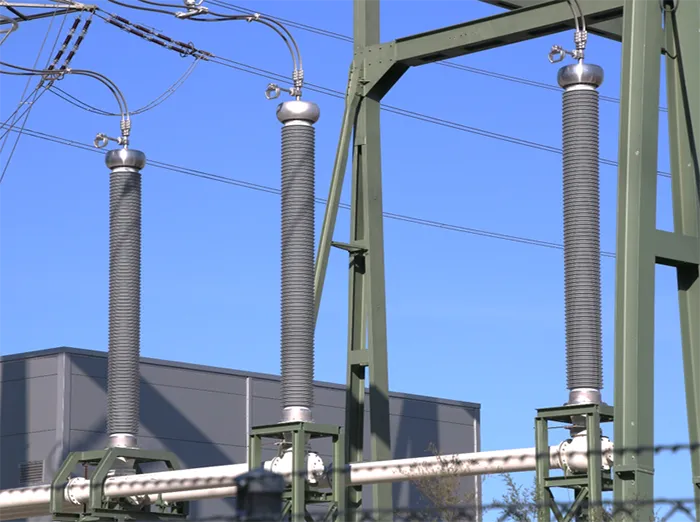
With new regulations in Europe (e.g. REACH/SVHC) as well as in countries such as the U.K., India and Australia, use of SF6 shall be limited and sunrise dates are already defined for different system voltage classes (≤145 kV and >145 kV) to phase out its application in HV apparatus by 2032 and 2036 respectively.
In the case of GIS bushings, there are least two solutions: application of alternative gases or use of dry technical air with higher maximum service pressure (MSP) – typically in the range 10…14 bar gauge to compensate for lower initial electrical strength. Despite the greater pressure, an increase of at least one diameter class will normally be required.
For alternative gases there is also the option to manage the lower electrical strength by increasing pressure or diameter. Care must then be taken with regards to compatibility of materials (e.g. metal, polymeric material, sealings) insofar as the decomposition products of FN and FK gas mixtures. Several compatibility investigations have already been carried out and indicate that special care must be taken to protect both the flange assembly glue and sealing rings. Managing FRP tube compatibility can be achieved using the same measures as against SF6 decomposition by-products.
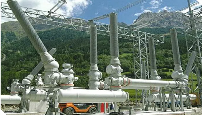
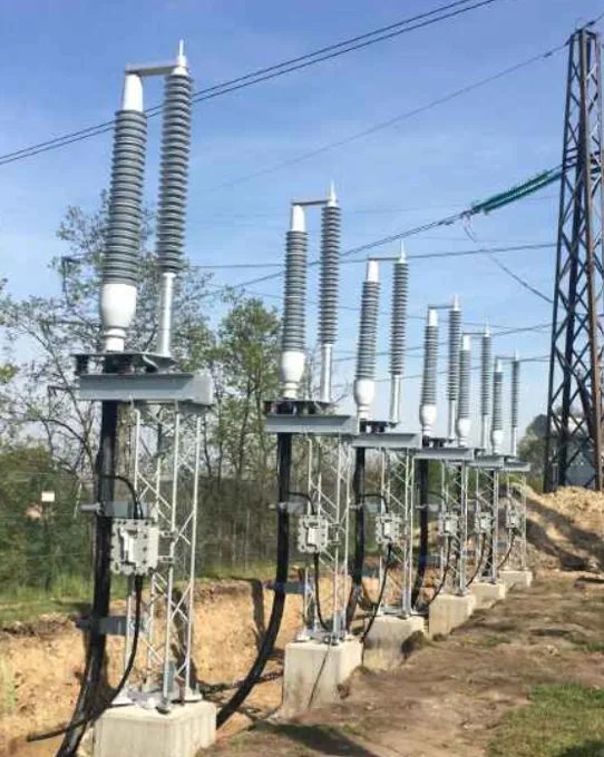
GIS is a space saving concept as demonstrated by the 420 kV hybrid substation at Simbach am Inn in Germany (see Fig. 2). There, the technology chosen aimed to use best practice in reducing the station’s footprint combined with highest system reliability as well as strong public acceptance. The last factor has become increasingly important for approval of new HV infrastructure. For example, the space and land area requirement for this project was only 10 to 20% that of a conventional air-insulated switching field with conventional live tank or dead tank circuit breakers, post insulators, ITs, surge arresters and related disconnectors.
Compact substations offer significant reduction in visual impact, and the life of such hybrid substations is the same or longer than for conventional substations since they are unaffected by environmental stresses. LCA and TCO calculations both reveal the benefits that help convince TSOs and public stakeholders to apply this technology in the future.

Composite Station Posts
Composite solid core station post insulators according to IEC 62231 offer advantages up to 245 kV (e.g. pollution resistance, resilience, seismic performance, less weight). Equivalent insulators for the North American market are standardized in ANSI C29.18. IEC and ANSI versions differ mainly in routine, sample and type test requirements. Also, ANSI has a higher level of dimensional specifications in terms of TR classes, derived from the long-established porcelain standard, ANSI C29.9.
For voltage classes above 245 kV, composite hollow station posts (CHSP) are preferred. These are typically governed by IEC 62772, especially since there are virtually no limits in single unit length and diameter (see Fig. 3). Solid media (e.g. foam) filled CHSPs are applied in the medium segment while the upper end ≥765 kV is typically filled with insulating gas. IEC 62722 was recently revised, in parallel to IEC 61462, to reflect the latest internal and external interface testing requirements.
Applications include:
• Bus bar supports (substations);
• Disconnector switches;
• HVDC converters;
• HVDC substations in high-polluted areas;
• HVDC substations near to marine environment (offshore energy facilities);
• HVDC and HVAC in seismic critical areas;
• UHV applications (replacing porcelain due to weight and superior pollution performance);
• FACTS / platforms (UPFC, SVC, capacitive and reactive compensators);
• Coil supports;
• Optical CT/VT supports;
• Optical fiber bushings (station post type).
CHSPs having more than 10m length and >580mm internal tube diameter have already been developed for large HVDC links where the coil acts as a reactor at the converter station. Multiple CHSPs, according to IEC 62772, are filled with gas under pressure, which is monitored and controlled. The monitoring system is the weak link for potential leakage although HCIs that are properly designed and tested for this application can be considered as offering a ‘lifetime seal’.
The concept of lifetime seal considers the leakage rate obtained during the routine tightness test. Based on maximum leakage rate measured, allows calculating total loss of pressure over 40 years application/service life. For example, quality units show loss of pressure of less than 10% meaning that, if gauge pressure is set to 0.5 bar, the loss over 40 years is less than 50 mbar. This ensures that there will still be sufficient overpressure to protect the hollow volume inside from ingress of humid air and moisture.
The main load on composite post insulators in coil applications is compression and CHSPs are preferred for this application because of their superior single-unit mechanical design along with excellent performance of hydrophobic silicone under pollution and DC voltage stress. In disconnector switch applications, the main load is bending during operation and due to additional loads. For proper function of the contact systems of these switches, stiffness must be high to secure low deflection under load. This can be achieved given the high moments of inertia of large diameter CHSPs.
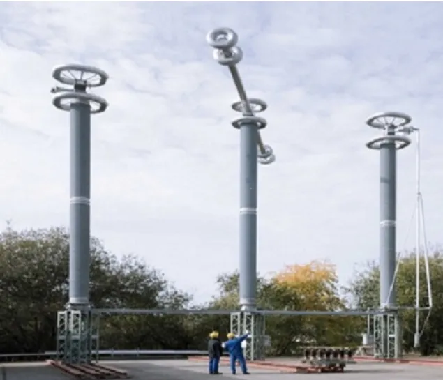
Other drivers favoring application of solid and hollow core composite station posts are seismic resistance, high mechanical impact strength and failure modes that do not exhibit bursting, explosion or emission of fragments.
Hollow post insulators are also the base technology underlying optical diagnostic/monitoring equipment and net level of optical instrument transformers, usually placed on the head or inside a hollow post insulator. The hollow composite station post insulator also acts as mechanical support for diagnostic/measuring devices with connected conductor and serves as insulating bushing for the optical fiber fed through the hollow core. Typically, the internal hollow volume in these applications is filled by an insulating foam or jelly, although gas is used in rare cases.

Cable Terminations
Cable terminations for HVAC and HVDC are now increasingly important, especially in the latter case for marine and land cable transmission projects at 320 and 525 kV system voltage. Presently, offshore wind farms and photovoltaic generation are connected using 320 kV cable system technology in the North Sea and Baltic Sea (i.e. Germany, U.K., Poland and Scandinavia) as well as in the Mediterranean (e.g. Tyrrhenian Link, Montenegro-Italy, Attica-Crete and Adriatic Link).
With growing power generation capacity, however, 525 kV transmission technology has been selected for future such connections as well as for long-distance transmission technology (marine and land cables). Examples include the Süd Link and Süd Ost Link as well as future 2 GW transmission projects across Germany. All generation for these applications was selected for being environmentally friendly “green” resources and replacing fossil and nuclear fuel used for decades. This change has been called Energiewende in Germany and is part of the political debate since 2015. Similar projects are now planned in the U.K., Scandinavia, Poland and Benelux.
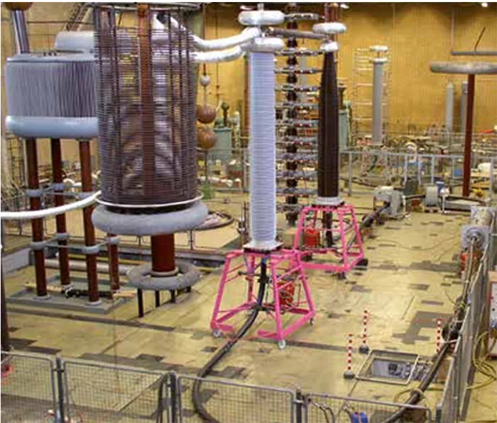
Technical expectations of these relatively new products including DC land cables and related joint and termination accessories is high, especially with regards to reliability and longevity. Nonetheless, experience is still limited for 525 kV such systems. The cable termination, for example, must be equipped with composite hollow insulators of large dimension in terms of diameter and length, e.g. the SOL cable termination for high pollution class has a length of 6500 mm. Terminations are filled with gas (see Fig. 5).
The reasons for choosing HCIs include:
• High-pollution resistance of their silicone housings;
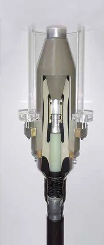
• Oil-free designs offering no risk of explosion and/or oil contamination in case of failure such as from short circuit. Figs 4 & 5 show dry type and gas-insulated oil-free terminations. Filling can also employ alternative gases;
• High mechanical impact strength along with a non-critical failure mode (i.e. no burst or emission of sharp elements);
• Flexible length and diameter in design of the stress cone/field grading element (see Fig. 6).

Trends, Challenges & Future Developments
A. Composite Hollow Insulators
• Modern composite hollow core insulators (HCIs) are manufactured using environmentally friendly processes with a sustainable and transparent supply chain and low CO2 footprint.
• Addition vulcanizing (platinum catalyzed) silicone systems are replacing peroxide curing systems. Addition curing systems do not emit hazardous volatile compounds and are fully in compliance with REACH/SVHC regulations. This also applies for other polymeric materials employed.
• Life-cycle assessment (LCA), i.e. cradle to grave considerations, is required and must demonstrate all related efforts as well as net advantages and disadvantages – not only in terms of cost but also environmental impact.
• Alternative gases and their decomposition products must be considered and HCIs are equipped accordingly.
• With increasing demand for EHV, UHV and HVDC solutions, future composite insulators designs need to be realized in extreme dimensions, e.g. lengths over 12m and inner diameters larger than 1000mm. Suitable manufacturing processes will need to be developed or enlarged.
• Alternative gases show lower electrical strength than SF6 and this will mean higher internal pressures for insulation. HCI designs for such applications will need to accommodate higher maximum service pressures (MSP), according to IEC 61462, resulting in higher SIP as well as higher routine testing pressure (i.e. 2 x MSP). Designs will have to be upgraded to allow more robust, higher-strength insulators.
• The total cost of ownership (TCO) approach considers all parameters, not only the cost (price) of materials. OEMs/TSOs are increasingly adopting such a philosophy, which contains LCA assessment and a range of other input parameters resulting from SHE, handling and maintenance over the full service/operating life of HV apparatus.
• Aspects such as ‘hardening’ substations against terror attack are key promoters for application of HCIs at substations.
B. GIS Bushings
• Composite insulators will increasingly replace porcelain due to reasons on better pollution performance and safety.
• Alternative gases/dry air will replace SF6 due to REACH regulations.
• Achieving compact design given the lower electrical strength of alternative gases will represent a challenge.
• Electrical field grading/field control technology will be an effective design tool to reduce diameters and allow more compact bushing designs.
C. Composite Station Posts
• Composite insulators will replace porcelain due to superior pollution performance and seismic resistance.
• Light weight, high-strength, and design as well as manufacturing flexibility are enabling application of CHSPs, with gas or foam filling media, for voltage classes exceeding 550 kV EHV AC, 800 kV HVDC and 1200 kV UHV AC.
• The ‘lifetime seal’ concept for CHSPs will help avoid need for expensive and vulnerable gas monitoring systems for gas-filled units.
• Over the next 20 years, composite station post insulators are expected to outperform and replace conventional ceramic insulators in all applications due to their economic, ecological and technical advantages. This also considers their evaluation according to the TCO model which includes initial product costs, supply chain, environmental requirements, maintenance, lifetime and risk assumptions.

D. Cable Terminations
Modern cable terminations are oil-free (for safety and environmental constraints) and use either dry-type or gas-filled technology. Dry types can be realized with different technologies, based on the intellectual property of the manufacturer.
• Dry-types are replacing oil-filled, with gas filled insulation for higher voltage classes.
• Composite insulators will increasingly replace porcelain types due to SHE constraints.
• Plug-in technology for easier handling and installation is the trend since most failures are caused by improper connection and installation.
• Condenser style bushings (resin-impregnated condenser core – RIS/RIP style) are alternatives to gas-filled solutions and fall in the ‘dry type’ category.
E. Optical Instrument Transformers (ITs)
Conventional instrument transformers (ITs) use SF6 gas or oil as insulating media to embed and isolate the transformer windings. This design principle has been proven for decades and is highly reliable. Over the past 20 years, however, a new IT principle has emerged based on optical physical effects.
Current transformers (CTs) have reached a high degree of maturity and acceptance by TSOs (see Fig. 7). The active optical CT head is placed on top of a hollow post insulator with optical fibers connected to it. The hollow post insulator acts as an optical fiber bushing accommodating a bundle of fibers internally embedded with a gas, liquid or polymeric insulation medium.
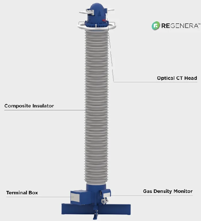
Similar optical principles are also used at HVDC converter stations and for monitoring/diagnostic purposes at substations and on overhead transmission lines (e.g. for temperature measurement, fault location, etc.). Insulation between high voltage (where the sensors are placed) and ground is realized by ‘signal columns’ which are slim HCI elements, typically as tension or suspension units.


References
[1] IEC 61462:2023, Composite Hollow Insulators – Pressurized and unpressurized insulators for use in electrical equipment with rated voltage greater than 1000V – Definitions, test methods, acceptance criteria and design recommendations.
[2] https://echa.europa.eu/
[3] CIGRE Technical Brochure No. 849, Electric performance of new non-SF₆ gases and gas mixtures for gas insulated systems, October 2021.
[4] C4-FN Mixtures for High-Voltage Equipment, Handbook, GE Vernova, Hitachi Energy, May 2023.
[5] C.H. Olsen et. al, Diffusion of CO2 through Polymer Membranes, Environmental Impact V, www.witpress.com, ISSN 1743-3541 (on-line), WIT Transactions on Ecology and the Environment, Vol. 245, © 2020 WIT Press.
[6] Y. Tu et al., Feasibility of C3F7CN/CO2 gas mixtures in high-voltage, High Volt., 2020, Vol. 5 Issue 4, pp. 377-386, this is an open access article published by the IET and CEPRI under the Creative Commons Attribution: Non-commercial License, (http://creativecommons.org/licenses/by-nc-nd/3.0/)
[7] Y. Li, Study on the thermal decomposition character-istics of C4F7N–CO2 mixture as ecofriendly gas-insulating medium, High Volt., 2020, Vol. 5 Issue 1, pp. 46-52 This is an open access article published by the IET and CEPRI under the Creative Commons Attribution: Non-commercial License, (http://creativecommons.org/licenses/by-nc/3.0/)
[8] IEC 62231-1:2015. Composite station post insulators for substations with AC voltages greater than 1 000 V up to 245 kV – Part 1: Dimensional, mechanical and electrical characteristics.
[9] ANSI C29.19:2020. Composite Station Post Insulators.
[10] IEC 62772:2023. Composite hollow core station post insulators for substations with a.c. voltage greater than 1000 V and d.c. voltage greater than 1500 V – Definitions, test methods and acceptance criteria
[11] switchgearcontent.com
[12] www.powerandcable.com
[13] Prysmian Group, Technical Brochure: Click Fit® – High Voltage Accessories for Extruded Cables, Milano, Italy, 2023.
[14] J.M. Seifert, H. Ye; New Concepts in Voltage Grading, INMR 2015, MC-04, Munich, Oct. 15-17th, 2015.
[15] Patent Publication No. 20110017488; FIELD-CONTROLLED COMPOSITE INSULATOR AND METHOD FOR PRODUCING THE COMPOSITE INSULATOR, Lapp Insulators GmbH, 27.01.2011.
[16] Trench Group Ltd.; REGENERA® – Optical Current Transformers, Technical Product Brochure, www.trench-group.com, 2024.
[17] www.hspkoeln.de/en/products