At some point, all electrical equipment has an end-of-life-event (EOLE). Sometimes this event can be as benign as being removed and replaced with a newer device, but it can also be the by-product of a thunderous overload. In the case of distribution surge arresters, such a thunderous overload can trigger either a short or long-term outage.
It is during such event that the arrester’s disconnector becomes a major factor in system reliability. The disconnector has remained essentially dormant, in a sense, for the entire life of the arrester. But during an overload type EOLE, it is called upon to operate once and only once to protect the power system from a potentially long outage. Basically, this remarkable sentinel of the power system stands guard over the arrester for its entire service life. Then, once needed, it senses the fault, activates efficiently and separates the arrester ground lead from the arrester itself. This keeps the lights on, keeps the motors turning, and can have a major impact on the reliability of an electrical distribution system.
This past INMR article, contributed by Columnist Jonathan Woodworth, reported on the disconnector, its real role and related technological developments over the years.

Background
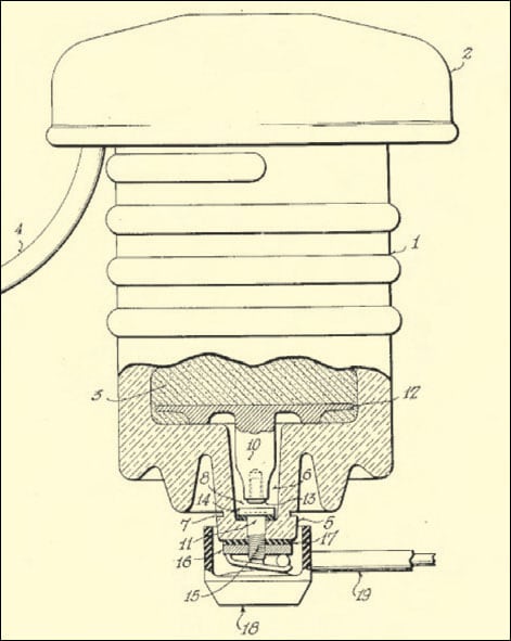
During the late 1930s, there was a great deal of effort by industry to develop an interrupter for arresters that would eliminate the need for a breaker operation to terminate the ground fault caused by a failed arrester. Most such effort was focused on the high voltage end of station arresters, but not all. In April of 1939, Ralph Earle applied for a patent on a device he called the “Automatic Circuit Interrupting Device” which then became a U.S. patent in 1942. It is quite likely that this was the first electrical device to use explosive black powder to assist in power system reliability by interrupting ground fault current flowing through a failed distribution arrester. Nearly 70 years later, virtually this same design concept is still being used but now called a ground lead disconnector (GLD). Though it is no longer regarded as a faulted circuit interrupter, it is still an indicator and a device that protects the system from long-term outages due to failed arresters.
CLICK TO ENLARGE
CLICK TO ENLARGE
The importance of the GLD with regard to system reliability is often underestimated and to a large extent also misunderstood.
The Modern Disconnector
An arrester disconnector is a device connected in series with an arrester and that separates the ground lead from the bottom of the arrester should it be overloaded and become a short circuit to earth. It is also known as a ground lead disconnector or isolator. The GLD operates only if power frequency fault current flows through the device during an arrester overload and should not respond in this way to a lightning or switching surge.
Basis of Operation
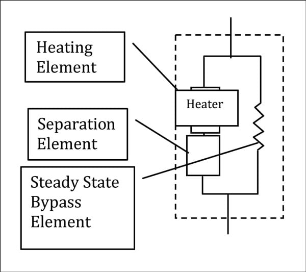
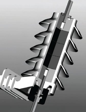
Commonly used designs available today include a heating element, a steady state bypass element and a separation element. Electrically speaking, all this is represented in Figure 4. There are several variations to this design, but all operate in fundamentally the same way. During steady state operation, the arrester leakage current is conducted around the heating element and the separation element, which is generally a small explosive device that is heat activated. During lightning surges, the heat generated in the disconnector from the heating element is not sufficient to ignite the separation element – designed such that it only operates when fault current flows through the device.

It is important to note that the standard arrester disconnector is not an interrupting device. It may break the fault current upon operation, but only under ideal conditions such as low fault currents. Since the disconnector does not interrupt fault current, an over-current device must operate when an arrester is overloaded and produces a short circuit to earth.
CLICK TO ENLARGE
System Conditions Relevant to Proper Use of Disconnector
As indicated above, the GLD is only activated from power frequency fault current. Because of this operational requirement, ungrounded systems and impedance grounded systems might not trigger its operation during an end-of-life-event. While some disconnector designs do have sensitivity down to the 1 amp fault current range, most do not. If disconnectors could routinely reach this low current operating region, many ungrounded and impedance grounded circuits could utilize them.

Time Current Curve
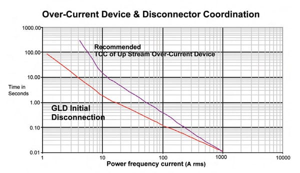
Each disconnector has a time current characteristic curve represented either graphically or in tabular from as shown in Figure 5. Since the disconnector is not a fault breaking or clearing device, the only curve that can properly be displayed is a disconnection initiation curve.
Disconnection initiation is defined as the first sign of external arc voltage across the device during its operation. The time current curve can be modified by adjusting how long it takes to heat the black powder to ignition temperature – for most modern GLDs, about 180°C. This sets one of the constraints of the device since the material near the black powder must be able to withstand such temperature without impeding the separation event.
CLICK TO ENLARGE
There are two common means of heating the separation element and a resistive material that converts energy into heat is quite often used. Resistance wire such as nichrome is popular because of its high temperature capability and good ageing characteristics. The location, length, and wire diameter determine heating characteristics and since these are quite measurable, heating time and ignition time can be accurately predicted. Locating the black powder relative to the heating element is critical.
A second popular method is to use the heat from the arc that is developed across a small physical gap during the fault current event. This is the method first developed back in 1939 and still works well today – a testament to the quality and cost-effectiveness of the original concept. While virtually every other feature of the distribution arrester has changed during the past seven decades, this one lives on.
Controlling the thermal characteristics of an arc is not an easy task and this makes this second method of heating less predictable. However, with a few experimental trials, the method can still be effective. The bypass element then becomes part of this design concept because its resistance determines the current and voltage at which the gap will initiate the arc. Sometimes, the bypass element can act as a heater at currents below an arcing level and can raise the temperature of the black powder to ignition temperature. If the GLD design depends on this dual duty of the bypass resistor, the material of the resistor is important and needs to be robust enough to handle high temperatures without degrading the ignition process. For arresters with no leakage current, the bypass resistor can be eliminated.
Coordination with Over-Current Devices
If an over-current device is upstream of an arrester equipped with a disconnector, it is possible for the over-current to be faster than disconnector’s ignition capability. It is therefore prudent for the user of such devices to coordinate the disconnector’s initial disconnection curve with the minimum melt curve of the over-current device. It can be generally assumed that if the overcurrent device is slower than a typical 20K fuse-link curve, then coordination with the disconnector is attained.
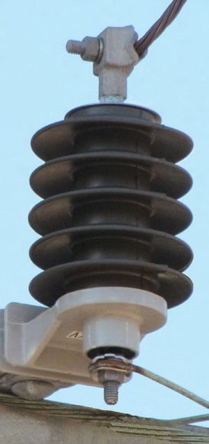
Safety Aspects of Disconnectors
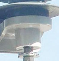
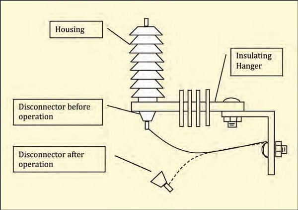
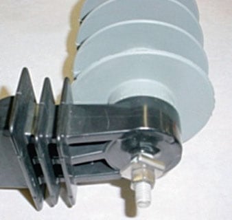
Disconnectors are generally installed at the earth end of the arrester, as shown in Figure 6. In this configuration, the bottom of the arrester becomes energized at line potential after the disconnector separates and the arrester becomes a low impedance to ground. This voltage distribution on the arrester is quite different from that more commonly seen at steady state. It is therefore important that users of this type arrester be aware that full line potential can exist at the bottom of the arrester where it is normally at or near earth potential. For this reason, the bottom of the arrester should always be treated as if it could be at line potential.
Yet another safety aspect to consider is that when the powder is heated to its activation temperature, it will separate the disconnector with considerable force and speed. This could cause the expulsion of small fragments and sparks. As stated above, since the GLD is not a fault clearing or breaking device, a resulting power frequency arc might be sustained for several cycles. This arc is capable of melting metal and plastic parts which may drop to the ground and, in locations susceptible to high fire risk, this may prove a very undesirable affect. A third safety issue to consider is that the disconnector device is heat activated and therefore should not be heated in an oven above 150°C since this could activate it. It should be noted, however, that an impact on a disconnector does not activate the powder, which is only heat activated. Nevertheless, care should be taken since, if the black power is impacted directly and heat is generated, it could ignite.
CLICK TO ENLARGE
GLD Reliability
The reliability of this device should be equal to or better than the arrester to which it is attached. If it’s not, a long term outage can result from a shorted arrester. This would make the arrester nearly impossible to find in daylight and harder still at night. One has only to ask any lines person who has hunted for a shorted arrester during a storm to restore service and they will no doubt offer harsh words about arresters with unreliable disconnectors.
Mechanical Considerations
Since the GLD is most often used as part of the earth terminal of an arrester, it must be able to withstand typical installation forces. This means it must be capable of tolerating 25-35 ft-lbs (34-47 Nm) without damage. This mechanical duty requires a hardy design.

GLD Standards
Both the IEC and IEEE arrester standards address only two aspects of the GLD. First the durability tests (Operating Duty, High Current and Low Current) must be completed with the GLD connected. During such tests, the device must not operate. The second aspect covered is the development of a disconnect curve. Each design must be tested at 20, 80, 200 and 800 amps and the resulting time to begin disconnect recorded.
These present standards are deficient in several respects and need to be modified in the near future. For one, they do not consider reliability of the device nor its sealing system or ageing behavior. Secondly, they do not consider operational tests above 800 amps and this level is routinely encountered in the field.
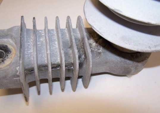
Insulating Bracket Considerations
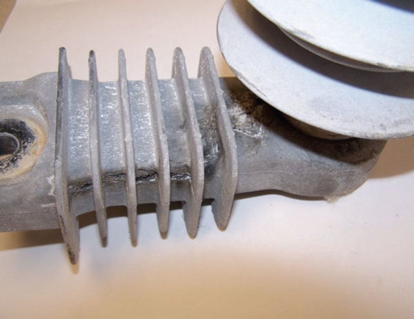
From Figure 6 it can be surmised that once the disconnector has operated, the line to earth potential is then stressed across the insulating hanger. This stress could lead to tracking over the hanger to earth if the disconnected unit is allowed to remain energized for long periods of time. For example, the long term electrical and environmental withstand characteristics of the insulating hanger will need to be increased if an arrester is allowed to remain energized for more than a year. Figure 7 provides an example of what could happen when the arrester is allowed to remain energized for such a period after the disconnector has operated.
CLICK TO ENLARGE
Installation Considerations & Lead Management
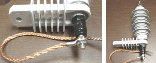
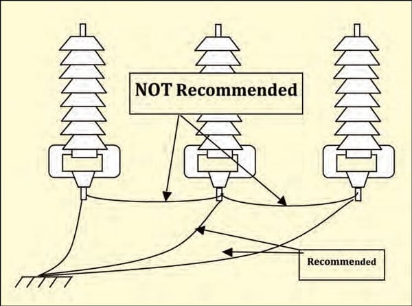
It is important to consider that when the disconnector operates and does disconnect the earth end of the arrester, the attached lead must have adequate length to allow it to create a gap between the bottom of the arrester and the disconnected half of the device. The flexibility of the lead also needs to be considered to ensure that the device can create such a gap. Typically, bus bar will cause a disconnecting problem while ordinary flexible lead is adequate. Solid or stranded conductors with diameters of up to 1 cm are generally easily disconnected from the arrester on typical devices.
When arresters are mounted on a cross arm in parallel to one another, it is important that the arrester in the middle not have its earth lead bound in place by the two outside units. This can lead to a sustained outage even though the disconnector did activate properly in an attempt to isolate the arrester (see Figure 8)
CLICK TO ENLARGE
Transport & Disposal
Due to the fact that arrester disconnectors contain an activation element that is capable of exploding (so as to separate the ground lead when exposed to the heat of ground fault current), it is also capable of operating this same way if put into a fire. Therefore disposal should obviously not require incineration.
According to UN regulations regarding dangerous materials, the GLD falls into Class 1 Explosive Material. However, with appropriate testing or modification, the GLD can be moved to a different classification. If the GLD is manufactured in such a way that it will not create a projectile if caught in a fire, it can be classified as a non-dangerous good and transport concerns are no longer an issue. This does raise the question of how to safely transport arresters by truck. If an arrester is already equipped with a transportation-safe disconnector, then no special precautions are needed. However, if it is a design manufactured prior to 2005, then it is suggested that the arresters be placed inside a metal enclosed chamber as routinely found on many utility vehicles. If that’s not possible, the best solution is to wire the GLD end of the arrester to something substantial or to its own high voltage end.
Disconnectors Used on Transmission Line Arresters
The TLA disconnector functions in a similar manner to distribution voltage units, however it must be able to withstand different stresses without operating. It is important to note that any disconnector applied to a transmission line arrester should be tested with higher current TLD tests as part of the certification process. As discussed earlier, since the separation element is heat activated, if the switching surge of a transmission line is of long enough duration or amplitude, it could cause enough heat to develop in the GLD to activate it.
The mechanical withstand capability of a disconnector becomes an important consideration when applying them on transmission line arresters. If the TLA is put into service such that the GLD is mechanically stressed over its life or is in a configuration that results in periodic stress during windstorms, the mechanical strength must be known and robust enough to survive such conditions.
The Future Disconnector
Future possibilities include:
1. Interrupting Disconnector: This device does not yet exist but is one that perhaps should be considered by arrester manufacturers since it could eliminate the blink on the power system in the event of an overloaded and failed arrester.
2. Substation Disconnector: This is a device mounted on HV devices that could be used to disconnect this type of arrester much as it does for distribution arresters.
3. Very Visible Disconnectors: Oftentimes, line personnel overlook a failed arrester because the arrester disconnector after functioning is not obvious. A clearer visual sign of arrester overload is needed, more than simply the earth lead separating from the arrester.
4. GLD for Delta, Ungrounded & Impedance Grounded Systems: Such a GLD should be able to operate reliably at 1 amp of ground current. This could make the GLD a guardian of many more power systems than at present.
5. A GLD to be Used on an Externally Gapped Line Arrester (EGLA) to Show Failure
6. A GLD that can be Put in a Lead and Used to Disconnect Other Equipment that Can Fault and Cause a Long-term System Outage
Summary
The ground lead disconnector is clearly an important option to consider when purchasing an arrester. If the system to which it is to be applied has ground fault current available, then this device should be considered for the benefit of improved system reliability. In particular, if designed for lower currents, it could become the overload sentinel for all power system arrester applications.