IEC 61284, the standard governing corona and RIV tests on transmission line assemblies for HVAC applications, allows two test methods – the voltage method and the voltage gradient method. The former specifies a fixed test voltage to be applied to the transmission line assembly under test whereby there is no corona. The transmission line assembly is set up to simulate service conditions by detailing the proximity of grounded planes and tower structures. Hence, testing transmission line assemblies with this method involves simplification of a transmission line configuration to a typical laboratory set-up with manageable physical dimensions. While the voltage method is straightforward and easily understood, the dimensions are only suitable for typical conventional structures. If dimensions are substantially different, the standard suggests that alternative dimensions may be agreed between purchaser and supplier.
The voltage gradient method, on the other hand, omits details of structures surrounding the transmission line assembly. Rather, it emphasises assimilation of electric field in the area around conductors or conductor bundles where the insulator assembly and hardware are to be installed. The dominant components affecting electric field distribution on transmission lines are the phase conductors. As such, the voltage gradient method specifies a fixed voltage gradient at the surface of the test conductor at which there is no corona on the assembly. Setting up a transmission line assembly for testing using the gradient method is much simpler than the voltage method. It is also a more accurate evaluation for purchaser and supplier to consider since proximity effect of the set-up surroundings can be taken into account by means of calibration. Ziqin Li of Kinectrics in Canada outlines key considerations behind corona and RIV tests on transmission line assemblies for both HVAC and HVDC applications.
Corona & RIV Tests Using Voltage Method
Testing Transmission Line Assemblies for HVAC Applications
The governing standard for corona and RIV tests on transmission line assemblies for HVAC application is IEC 61284. This standard gives a set of set-up physical dimensions for transmission lines of variable voltage classes. Utilizing the dimensions to set up a transmission line assembly for testing is straightforward but care must still be taken to reduce proximity effects of objects surrounding the set-up to ensure an accurate test on the assembly. To achieve this, grounded objects that are not part of the set-up should be as far away as possible, and in fact, the standard requires they be at least 1.4 times the distance between conductor and reference ground. Large objects such as laboratory walls and an overhead crane bridge should be farther away to minimize their effects. Utilities sometimes require that corona and RIV tests on transmission line assemblies be performed using a specific single-phase set-up defined only by height of the conductor from the laboratory floor. Voltage specified is determined based on equivalent voltage gradient between a three-phase transmission line and a single-phase laboratory test set-up. In this case, equivalence is determined by calculating the voltage gradient at mid-span of the threephase transmission line when it is energized at the desired corona extinction voltage. Then, voltage required to apply to the single-phase conductor of given height is calculated to stress it to that voltage gradient. However this ignores the fact that voltage gradient of the conductor at the tower is different from that at mid-span and that voltage gradient of a single-phase conductor in the laboratory is affected not only by the floor but also by other objects surrounding the set-up. Such a practice can lead to inaccurate test results and should be avoided.

Testing Transmission Assemblies for HVDC Applications
Onset corona discharge under applied negative voltage appears in the form of ‘Trichel pulses’ whereas it appears in the form of onset streamers under applied positive voltage. Experiments show that onset voltage for both discharges is essentially the same given the same electrode arrangement. The Trichel pulse, however, generates significantly lower RIV than generated by positive onset streamers. Therefore, corona and RIV performance of transmission line assemblies for bi-polar DC application needs to be evaluated under applied positive voltage only. Moreover, due to symmetry of the bi-polar configuration, the potentials at all points on a virtual vertical plane in parallel with pole conductors and located at their midpoint are zero. Therefore, laboratory set-up of a bi-polar transmission line reduces to a single pole conductor with vertical grounded plane.
Testing Hardware on Conductor Surface at Mid-Span
When testing hardware to be installed at mid-span, the worst case would be that it is installed at the lowest point of the line, closest to ground. Therefore, height from the test conductor used to simulate pole conductor to laboratory floor should be no more than the minimum height of the pole conductor. Also, distance of the test conductor from a vertical-grounded- plane, or laboratory wall, should be no greater than half pole spacing. Sometimes, this is a challenge and, in such cases, dimensions have to be changed to make the test possible while test voltage has to be adjusted to take account of this dimensional changes by using equation 1 below:
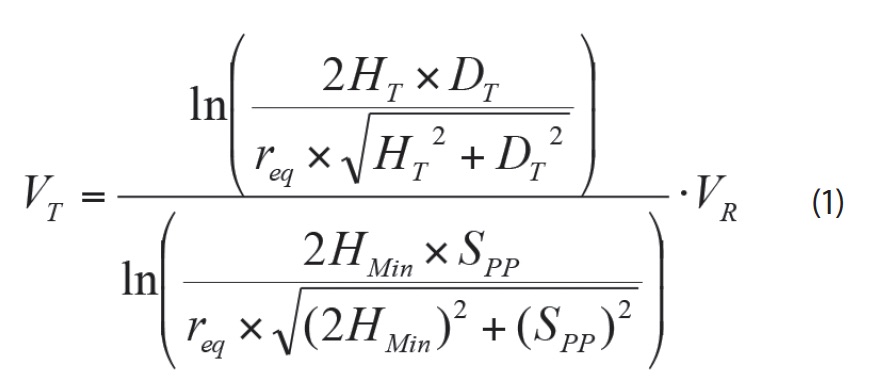
Where is VT test voltage on test conductor, VR is required corona extinction voltage, req is equivalent radius of pole conductor, HT is height of test conductor, DT is distance of test conductor to vertical plane, HMin is minimum height of pole conductor and Spp is spacing between pole conductors. Equivalent radius of the pole conductor bundle is determined using the following equation:
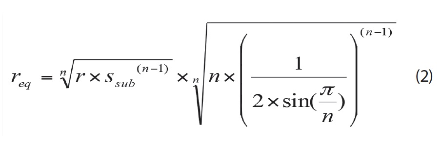
Where n is number of sub-conductors, r is radius of sub-conductors and Ssub is sub-conductor spacing.
It should be pointed out that these equations are valid only if sub-conductors are arranged in a circle with equal spacing. This adjustment of test voltage is based on the principle that the laboratory set-up must produce the same voltage gradient on test conductor as that on pole conductor when the transmission line is being operated at the required corona extinction voltage. However, this is not the same as the voltage gradient method. In fact, the formula for voltage adjustment is based on the assumption that there are no other objects besides test conductor, grounded plane and laboratory floor that could affect voltage gradient of the test conductor and that the test conductor is infinite in length. Voltage gradient on the test conductor is always higher than expected if there are proximity effects.

Testing Transmission Line Assemblies on Conductor Surface at Towers
In order to test transmission line assemblies for DC applications at towers using the voltage method, it is essential to set up a grounded plane that is in parallel with the test conductor and placed vertically at half the pole spacing from the test conductor. This physical dimension requires spacing that most testing laboratories can reasonably offer and, in most cases, the laboratory wall is utilized as the required vertical plane. The height of the transmission pole conductors from ground at the tower is usually substantially greater than ½ of the pole spacing. Simulating this physical dimension is a challenge to most testing laboratories. Therefore, height of the pole conductor to ground has to be dimensioned to an acceptable level for the laboratory set-up. It is not unreasonable to request that the laboratory set up the test conductor to half the pole spacing from the floor. Furthermore, when setting up transmission line assemblies in a laboratory environment, a tower cross-arm is necessary for suspension of the insulator assembly under test. This is usually done by an overhead crane hanging the simulated cross-arm above the floor. Hence, tower body is not essential for cross-arm support for laboratory set-up and could be omitted and voltage required to be applied to the insulator assembly and hardware under test has to be adjusted to reflect these dimensional alterations.
It is not difficult to find the voltage gradient of pole conductors at the tower at any given voltage if the towers are removed while keeping the physical locations of the pole conductors unchanged, i.e. a bi-polar transmission line without towers. Assuming that the grounded cross-arm hangs over the pole conductors, voltage gradient on the pole conductor would increase significantly, i.e. by 8 to 15% depending on pole spacing and distance of pole conductors from cross-arm. With introduction of a square tower body, the tower would stick out 1.0 to 2.0 m to the pole conductor from the virtual ground plane, depending on tower body size. Voltage gradient on the pole conductor at the tower location would increase only slightly, e.g. by 0.5 to 1.5%. If the ground were moved up to a distance of half the pole spacing from pole conductor, this would only increase electric field stress on the pole conductor by 2.0 to 3.0% since the cross-arm is already at ground potential. Therefore, net effect of keeping the cross-arm, omitting the tower body and moving the ground up to half pole spacing from pole conductor, is but a minor increase in voltage gradient on the pole conductor, e.g. by about 1.5 to 2.5%. It should be noted that these numbers are the result of evaluations assuming that pole conductor has infinite length. However, the conductor used in the laboratory has only finite length due to space limitations. It is estimated that voltage gradient at the center of the test conductor will be enhanced by 2 to 3% if the free length of test conductor is equal to height of the test conductor, in this case half the pole spacing.
Therefore, there should be a total downward adjustment on required test voltage of about 5% to yield an unbiased test when the voltage method is being used with the set-up dimensions given above. For example, the assembly should be tested at 475 kV in the laboratory and there should be no corona if a corona extinction voltage of 500 kV is required. It should be emphasized that grounded objects that are not part of the set-up should be as far away as possible. Diameter of the termination electrodes should be in the range of 1.2 to 1.5 times the diagonal of the test conductor to ensure no corona is generated from the ends of the test conductor. The voltage gradient method should be used if laboratory spacing cannot accommodate required set-up dimensions.

Testing Transmission Line Assemblies Using Voltage Gradient Method
Testing insulator assemblies and hardware for corona and RIV performances using the voltage gradient method includes two essential steps:
(1) Determine required corona extinction voltage gradient for a given insulator assembly and hardware based on its electrical stress under operating conditions;
(2) Test the laboratory set-up of the insulator assembly and hardware to the corona extinction voltage gradient through calibration.
As mentioned, the voltage gradient of the test conductor is affected not only by the essential components of the setup but also by other objects in the laboratory such as walls, ceiling, overhead crane, etc. The voltage method scales the voltage required for laboratory testing based on the voltage gradient that is determined by essential components, ignoring other surrounding objects, while the voltage gradient method takes them into account through ‘measuring’ voltage gradient on the conductor.
Device for Measuring Voltage Gradient on Conductors
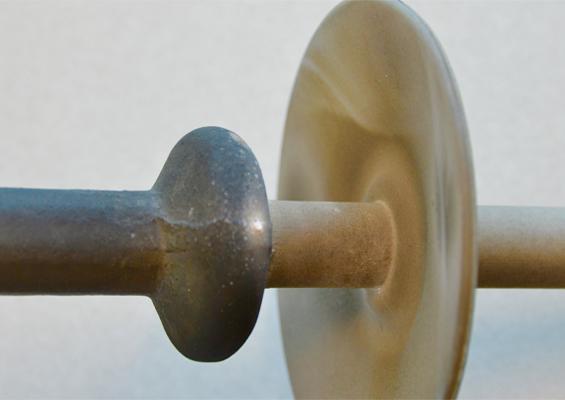
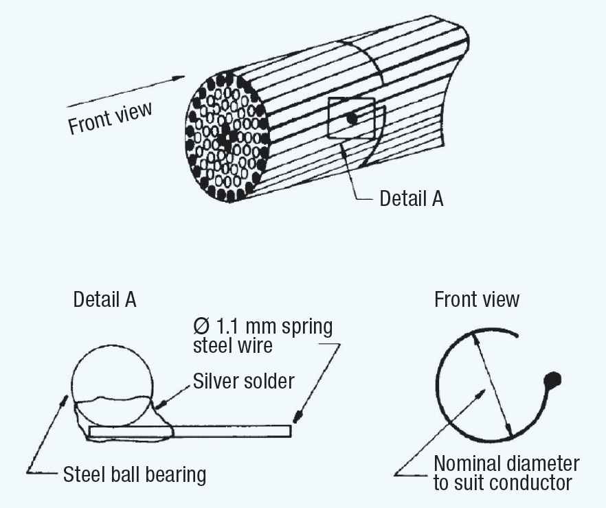
Researchers at the former Ontario Hydro Research Div. (now Kinectrics) and the National Research Council of Canada found that a sphere of 3.18 mm diameter (as in Fig 1) was most suitable for voltage gradient calibration of transmission line conductors. Larger spheres are better suited for substation bus conductors that normally have larger diameter. The steel spring wire used for the attachment is piano wire and is made by winding it on a mandrel of smaller diameter so that, when released, it gives the exact diameter of the target conductor. Voltage gradient calibration is based on the fact that onset discharge on the calibrating sphere, when attached to a conductor, is related to voltage gradient on the surface of the conductor.
CLICK TO ENLARGE
Calibration of calibrators is done first to establish electric field at conductor surface through onset of discharges at the sphere calibrator. Individual spheres are assigned inception voltage gradients based on a given geometry and conductor size. Accuracy of the calibrator is better than ±2%. Concentric cylinder geometry was used by researchers for calibration. Length of the cylinder was about 8 times its radius. There was no mention of how these dimensions were chosen but it is believed that researchers came to the conclusion that such a geometric configuration would ensure that end effects on electric field at the center of the concentric cylinder would be minimal. Hence, equation 3 is developed based on the assumption that the concentric cylinders having infinite length could be applied to this finite length of concentric cylinder geometry:
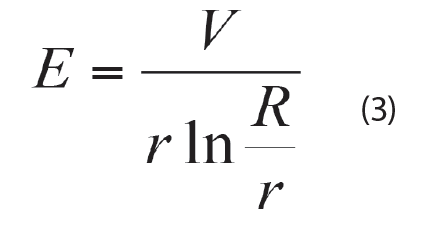 Where E is voltage gradient on conductor at middle of concentric cylinder, V is voltage on conductor, R is radius of concentric cylinder and r is radius of conductor. Calibration could also be done using a single conductor above the ground plane geometry, with the following constraints:
(1) Length of conductor shall be at least 8 times conductor height from the ground plane;
(2) Any grounded objects on either side of the conductor shall be at least 6 times conductor height from the ground plane.
Equation 4 is preferable to calculate the calibrator’s corona inception voltage gradient from the corona inception voltage obtained using this geometry:
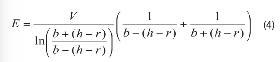
Where V is corona inception voltage of the calibrator on conductor, h is height of conductor to ground and r is radius of conductor
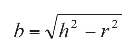
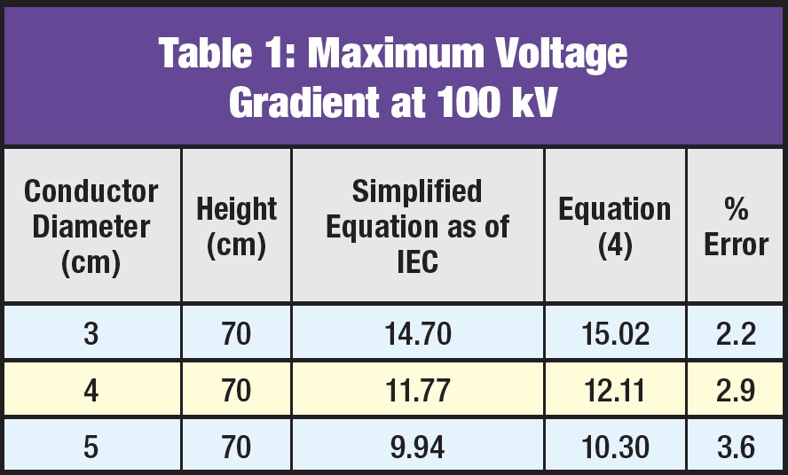
The equation recommended by IEC 61284 is a simplified version of equation 4 when the inequality equation of h>>r is satisfied and thus b ≈h . Using it could lead to an error of over 2% for commonly used conductors, as shown in Table 1.
Corona inception gradient of a calibrator on any given conductor is calibrated through the following steps:
(1) Mount the calibrator onto a conductor set-up for concentric cylinder geometry or single conductor above grounded plane geometry;
(2) Increase the voltage applied to conductor until corona discharge is observed on the spherical calibrator. Record corona inception voltage and then reduce the voltage until all corona on the calibrator ceases to exist;
(3) Repeat step 2 five times and take the average of these readings as the corona inception voltage of the calibrator on the conductor;
(4) Calculate corona inception voltage gradient of the calibrator for the conductor from the corona inception voltage using the appropriate equation given earlier. These calibration steps apply to both AC and DC voltages.

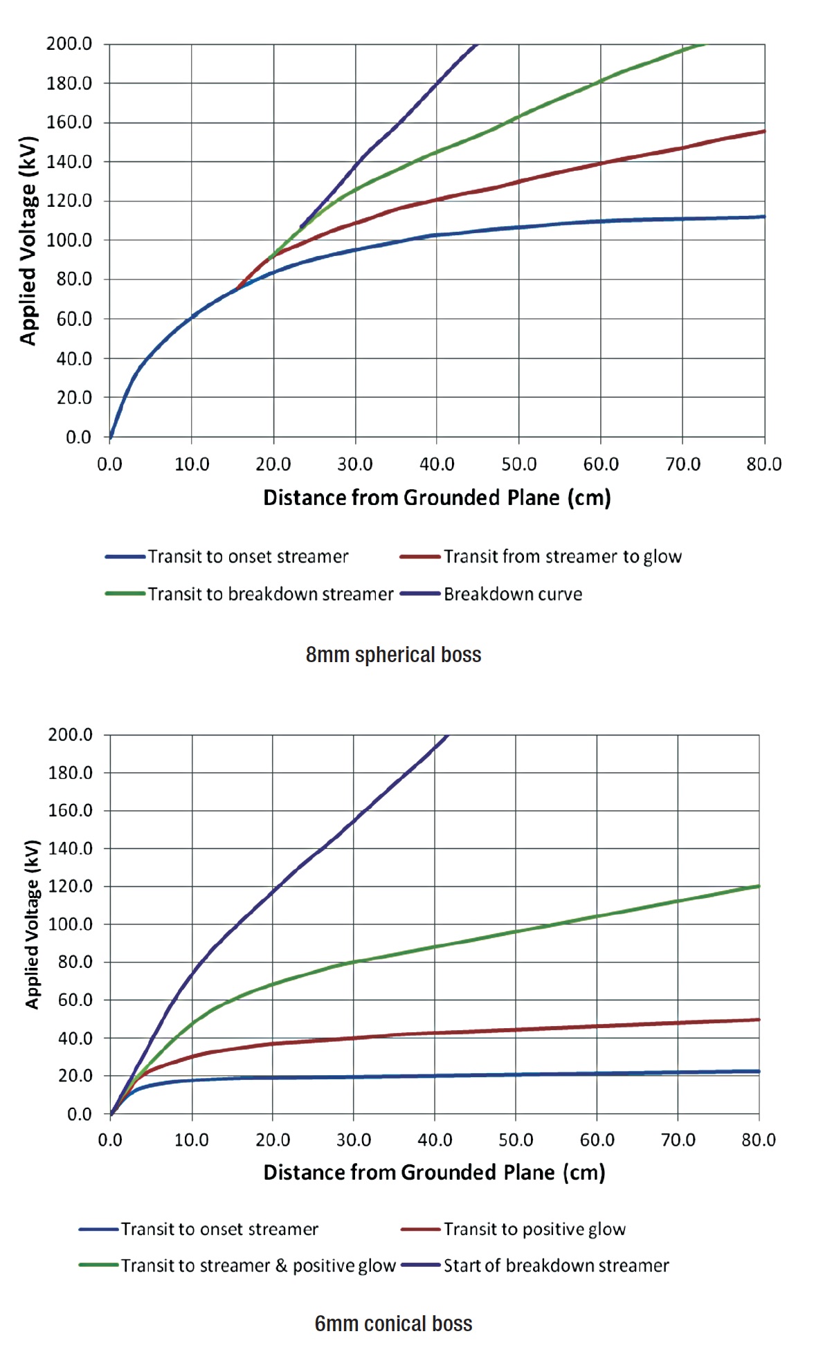
When calibrating under AC voltage, positive corona inception voltage is normally used. Positive corona discharges are easy to identify since the calibrator comes into negative glow corona (corona generated on the negative half-cycle) before onset of positive corona (corona generated on the positive half-cycle). Positive corona appears on the tip of the calibrator as repetitive sparking accompanying by a low-frequency crackling sound. When calibrating under DC voltage, care should be taken to ensure that a positive onset streamer is not confused with a positive breakdown streamer. As observed in research by Trinh and Jordan (shown in Fig. 2), repetitive sparking (onset streamer) occurs suddenly. The onset streamer transits to positive glow and then again to repetitive sparking (breakdown streamer).
CLICK TO ENLARGE
As noted in the case of a 6 mm conical boss, there is a narrow band of onset-streamers before the boss comes to a positive glow. Streamer discharges reappear as voltage further increases after the positive glow. The difference in streamer discharges before and after the positive glow is discharge energy being stronger for the latter. This could therefore lead to large error in voltage gradient calibration if taken during the calibrator calibration while another is taken when calibrating the voltage gradient on test conductor. Moreover, the inception voltage obtained for the same calibration is often slightly different from one observer to the next, depending on how onset of corona discharge is interpreted. To reduce such uncertainty, the technical team must go through training to ensure that each member uses the same technical criteria for observation. The safest way to reduce uncertainty is to use one person for the gradient calibration throughout the test project.
Voltage Gradient on AC Three-Phase Conductors
Voltage Gradient on Conductor Surface at Mid-Span
To test hardware that will be installed at mid-span, maximum voltage gradient on the conductor should be calculated by assuming the minimum height of the transmission line. For flat three-phase AC transmission systems, maximum voltage gradient appears on the center phase conductor at the peak of the voltage on the conductor. Maximum voltage gradient in this case could be calculated by using equations 5 and 6 below. The result from these equations is then multiplied by a factor of ~102.5% for commonly used transmission geometries to correct error due to the average- maximum approach when developing the equations.
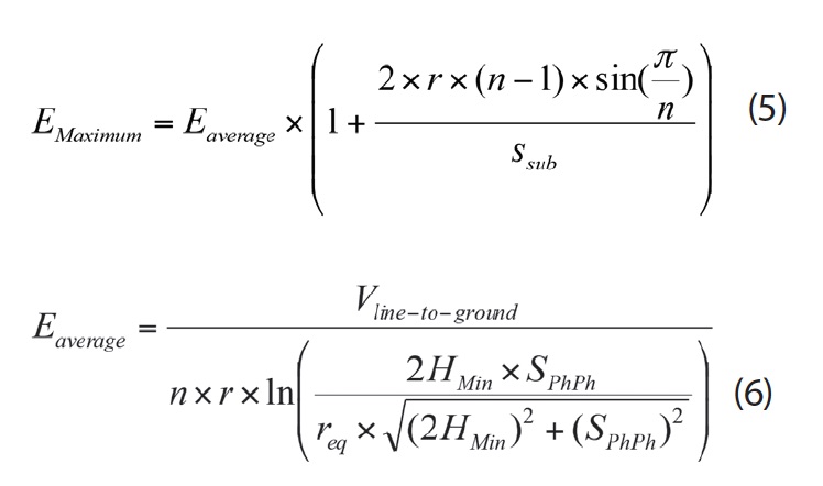
Where n is number of sub-conductors, req is equivalent radius of the conductor bundle as defined above, r is radius of sub-conductor, Ssub is sub-conductor spacing, HMin is minimum height of line and SPhPh is phase-to-phase spacing.
It should be noted again that the equation above is valid only if sub-conductors are arranged in a circle with equal spacing.
Voltage Gradient on Conductor Surface Near Towers
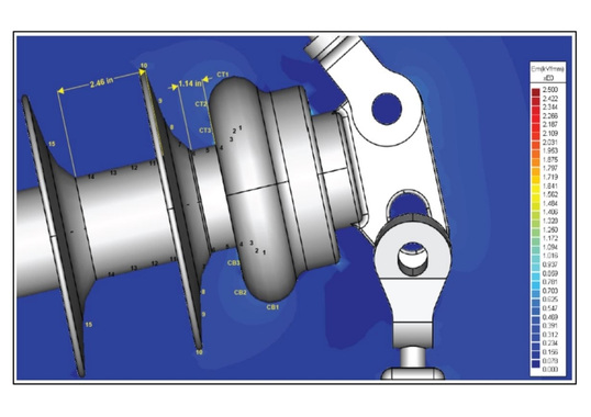
There is commercially available software that gives relatively accurate evaluations of voltage gradient on the conductor in the vicinity of transmission line towers of three-phase transmission systems. The uniqueness of this evaluation is that voltage gradients of interest are on the physically well-defined conductor surface and not on the tower structure. Hence, there is no need to simulate details of tower structure. A solid conducting structure with contour roughly similar to the contour of the tower will be as good as a detailed simulation of tower structure. To put this into perspective, voltage gradient of a conductor at the center of a square tower window would be almost the same as that of a conductor at the center of a circular tower window having same diameter, i.e. the same as that of the side of the square tower window. The length of the simulating conductor on the other hand has a larger effect on calculation results. Based on knowledge of the constraints for the calibration of the calibrator mentioned earlier, it is believed that the length of simulating conductors must be at least 8 times phase-to-phase spacing. As an empirical solution for flat arranged three-phase AC transmission systems, voltage gradient of the phase conductor in a tower window could be calculated as follows: assume the phase conductor is surrounded by a short cylinder having a diameter that best fits the center line of the transverse tower window cross-section while being at ground potential with the phase conductor at the required corona extinction line-to-ground voltage. A 10% enhancement from the voltage gradient at the center phase conductor calculated without the tower structure is often sufficient to take the tower structure into account.
Voltage Gradient on DC Conductors
Voltage Gradient on Conductor Surface at Mid-Span
It can be shown that the gradient of the pole conductor at mid-span can be calculated by first using equation 7. The value from this equation is then multiplied by a factor of ~102.5% for commonly used transmission geometries to correct error due to the average-maximum approach in developing the equation.
Where VR is required corona extinction voltage, ER is required voltage gradient, H is minimum height of the line, S is spacing between pole conductors and req is equivalent radius of the pole bundle as defined earlier.
Voltage Gradient on Conductor Surface Near Towers
As in the case of transmission line assembly for AC applications, commercially available software can be used to determine voltage gradient on the pole conductor near towers. By way of an empirical solution, calculation of voltage gradient on the pole conductor can done by assuming the cross-arm has infinite length and is placed right above and in parallel with the pole conductor. This solution is based on the fact that voltage gradient on the energized conductor of two cross conductors is nearly the same as that if the two conductors are in parallel.
Set-Up of Test Conductor
The first step when performing the corona and RIV test using the voltage gradient method is to determine required corona extinction voltage by taking into consideration:
(1) Maximum operating voltage of the transmission line on which the insulator assembly and hardware is to be installed;
(2) Altitude of the line;
(3) Surface ageing of hardware in service.
The second step is to determine the test conductor. It has been proven that a stranded conductor and a metal tube conductor having same diameter are interchangeable for corona and RIV tests since the test conductor is used mainly to establish an electric field around the insulator assembly and hardware. Metal tubes generally do not have exactly the same diameter as conductors commonly used by utilities. For example, a Canadian standard allows that diameter of tubing can differ from that of the conductor represented by only up to 5%. No such tolerance is given by the IEC standard. Once required corona extinction voltage has been established and test conductor chosen, the required corona extinction voltage gradient can be calculated using one of the methods discussed with the geometry of the line. The reason for using diameter of test conductor for voltage gradient calculation instead of diameter of design conductor is to limit effects on electric field distribution. These would be due to variations in diameter of test conductor to conductor- hardware interface area, while keeping electric field distribution virtually unchanged in other areas.
The third step is to calibrate the calibrator to be used for voltage gradient measurements (calibration) using the test conductor. After this preparation, the test conductor is ready to be set up with appropriate terminations attached. The test conductor shall be set up in the location where the transmission assembly is to be tested. It is not necessary to set up tower structures or the grounded plane since the voltage gradient method uses test voltage determined from actual measured voltage gradient of the test conductor. The relationship of the voltage applied to the test conductor and the voltage gradient on the test conductor where the assembly is to be installed is then established through calibration. The test voltage required to create the required corona extinction voltage gradient on the test conductor is then determined using the established voltage-gradient relationship.
The criterion for acceptance of a test conductor set-up set by the Canadian standard is that the test voltage determined shall be within ±20% of the maximum design phase-toground service voltage. The IEC standard raises this threshold to ±30% of maximum operating line-to-ground voltage. The terms of the voltage that these two standards refer to are different because they deal with different test specimens. However the principle is the same in both cases, i.e. to reproduce an electric field in the laboratory set-up similar to that of the transmission line represented. In this context, the term ‘required corona extinction voltage’ should be used. It should be pointed out that the essential components required for the set-up have to be in place when doing the test conductor voltage gradient calibration. For example, if a cross-arm is required for installation of the insulator assembly during testing, it should also be included in the set-up for calibration. Finally, the insulator assembly and hardware should be installed onto the test conductor only if its set-up is acceptable. Corona and RIV performance evaluation tests can then follow.
Conclusions
1. The voltage method could be used in corona and RIV tests on transmission line assemblies and hardware for both HVAC and HVDC applications if a test laboratory is able to accommodate the set-up dimensional requirements. Degree of proximity effects varies from one setup to another and therefore uncertainty of test results cannot be quantified. Controlling proximity effects is crucial to give an unbiased evaluation of corona and RIV performance of the assembly and hardware being tested.
2. The voltage gradient method takes the proximity effects into account through calibration and yields a more accurate evaluation of corona and RIV performance of the assembly and hardware being tested. It is also easier to set-up. Therefore, it is the preferred method for corona and RIV tests on transmission line assemblies and hardware