It is common knowledge that composite insulators used at transmission voltages must be equipped with properly dimensioned corona rings to reduce risk of erosion to their housings. Nonetheless, situations still occur where such insulators are either installed without rings or where these detach and fall off due to conductor vibration and/or improper installation.
The cases discussed in this past edited contribution to INMR by Cristian Gutierrez come from the 400 kV network in Venezuela and document what can happen to polymeric insulators on transmission lines without proper corona ring protection.
CASE 1: Palital-Furrial 400 kV Line
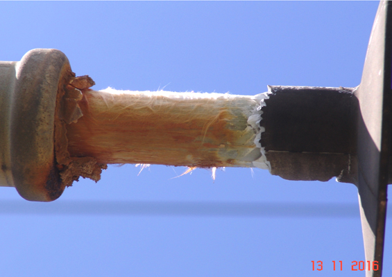
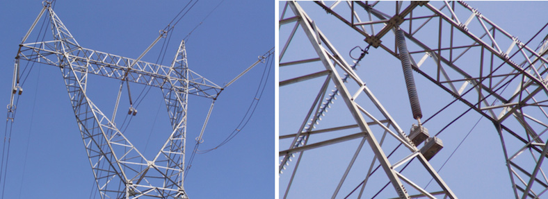
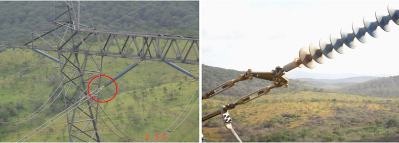
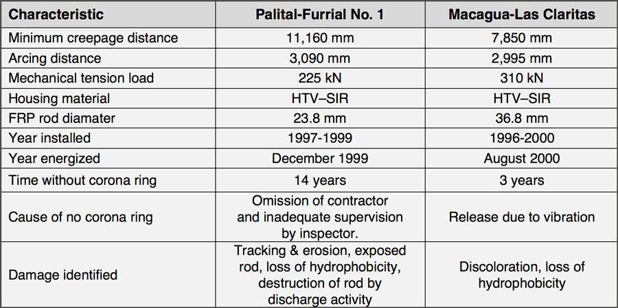
The No. 1 Palital-Furrial line runs 169 km and has 402 towers, of which 385 are suspension and 17 dead end. The route of this line, first energized in December 1999, is mostly flat and from 40 to 180 meters above sea level. On January 7, 2015, there was a single-phase fault with unsuccessful reclosing. Three minutes later, staff at the Operations Center staff attempted a manual reclose but this also proved unsuccessful due to the presence of a permanent fault. An aerial inspection was initiated that same day. According to information provided by Operations Center staff, the disturbance involved a single phase to ground fault (phase B) located about 7 km from the El Furrial Substation. During the aerial inspection, the point of failure was determined to have occurred at dead end tower no. 384. A polymeric insulator supporting the jumper conductor on phase B had failed mechanically and dropped the loop onto the structure.
The failed insulator on phase B was supporting the jumper (by-pass) mechanically, with an estimated weight of 600 pounds for all components. After assessing the damage, the failed insulator was replaced and all insulators on the structure were inspected. Special attention was given to the insulator on phase A since that it was just 9 meters from the phase B insulator and exposed to the same mechanical stresses and other service conditions.

Failure Analysis & Inspection Results
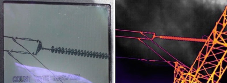
Because of the failure, a special team was formed to analyze and identify the factors that led to the insulator fracture. The objective was to take preventive measures to avoid further such failures on the line. One of the key steps in this regard was visual inspection and corona tests on all the line’s dead-end towers to assess the general condition of the insulation. This was conducted later that January using special UV camera equipment and the findings were as follows:
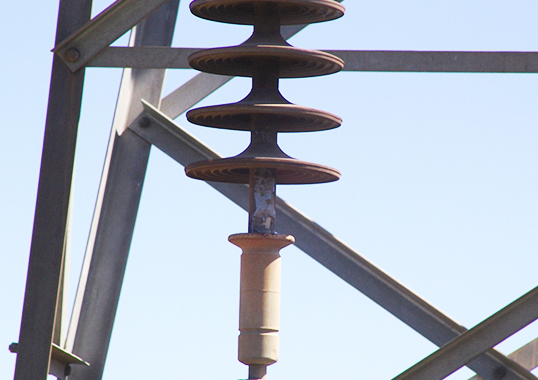
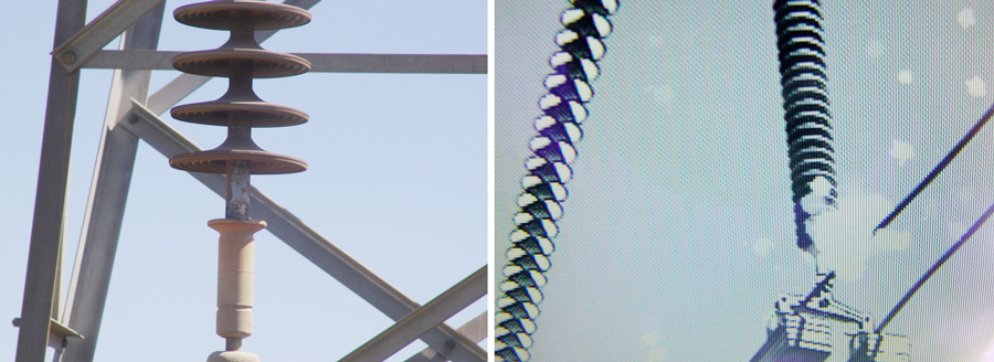
1. It was discovered that on several of the line’s 17 dead end towers (nos. 2, 4 and 384) the insulators supporting the jumper did not have corona rings. Intense corona activity and discoloration was observed on their sheds nearest the line potential (see Table 1).
2. On other dead-end towers (nos. 97, 100, 103, 128, 137, 300, 400 and 401) all auxiliary guidance insulators were equipped with corona rings and appeared in good condition, without physical evidence of corona activity.
3. Insulators located close to Palital Substation had a layer of dark contamination that adhered to sheds and this was attributed to a nearby area emitting industrial pollution. By contrast, no contamination was observed on insulators on tower no. 384, which is located in a clean area with much rainfall and sandy terrain.
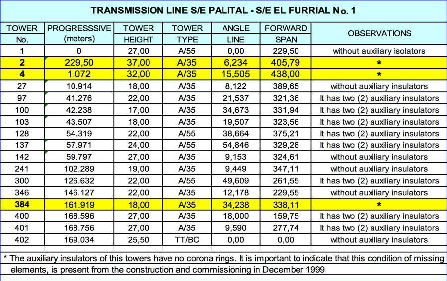
After completing the inspections, those insulators which had high corona activity (i.e. above 2000 photons/sec) were scheduled for replacement. Moreover, photos of towers nos. 2, 4 and 384 were taken to serve as a reference of the condition of their insulators at that time.
CASE 2: Macagua-Las Claritas 400 kV Line
The Macagua-Las Claritas 400 kV overhead line, commissioned in August 2000, runs 298 km and has 721 towers (671 suspension towers, 47 dead end towers). Some 90% of its route covers flat terrain and is between 50 and 150 meters above sea level. Aerial inspection in July 2011 detected that the corona ring at the energized end of the phase B insulator on tension tower no. 141 had become detached. This problem was monitored periodically and the insulator replaced in April 2014 based on the experience described in Case 1.
Inspection Results
Visual inspection as well as corona and thermography testing were performed on all insulators on tower no. 141, with special emphasis on the phase B insulator where the corona ring had detached and fallen off. The results:
• no damage was observed on the insulator housing;
• there was no significant temperature increase;
• corona activity was of medium intensity;
• the first 3 sheds of the insulator were discolored.
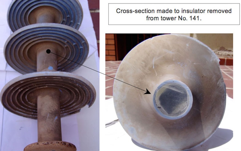
The insulator on tower No. 141 that showed medium corona activity due to the loss of its ring was removed from service and sent for detailed inspection. Two cross-section cuts were made 50 cm from each end of the insulator to check for leakage current and to assess physical condition.

Conclusions
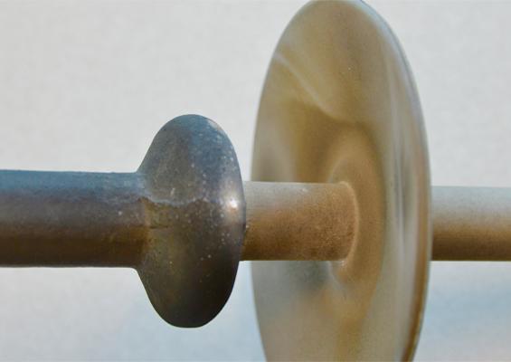
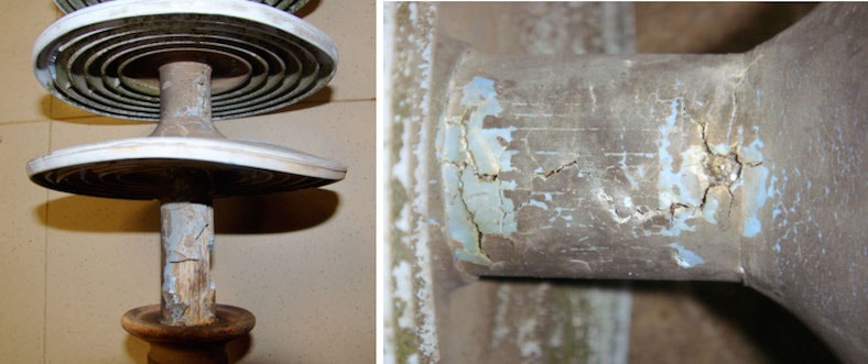
The two cases described demonstrate the importance of installing corona rings at the energized end of polymeric insulators used on 400 kV overhead lines. This is true for both suspension and tension towers since corona can reduce the effective service life of such insulators to less than 14 years. It is also important to take into account whether the route of a line passes areas with agricultural, maritime or industrial pollution since this will accelerate irreversible structural damage to such insulators. The outcomes described here were not due to manufacturing defects but rather to absence of the corona ring. This resulted in a high concentration of electric field, producing corona effects that permanently destroyed the silicone rubber housing and left the core rod exposed to the environment.
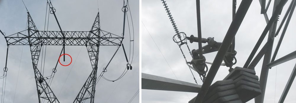
Corona rings designed and supplied by their manufacturer must be installed on polymeric insulators used at transmission voltages. Some manufacturers recommend grading rings at both ends of the insulator at higher transmission line voltages. It should be mandatory that corona rings be installed during construction of any line and, if such accessories are missing, the line should not be energized.
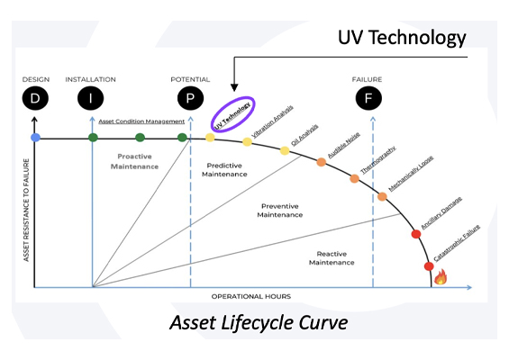
Visual inspection with binoculars and evaluation of corona activity using high sensitivity UV cameras can help detect problems affecting polymeric insulators. Both should therefore be part of routine annual or bi-annual inspections to prevent insulator failures on overhead transmission lines.
Suitable inspection procedures should be developed by utility maintenance departments to establish proper methodologies for visual inspection and detection of corona activity on polymeric insulators at close distance. Work methods must address such inspection with the line energized or de-energized and the main objective is to evaluate the physical operating condition of polymeric insulators and identify any units with higher risk of failure. Depending on maintenance resources, the inspection methodology should be performed tower by tower, climbing each structure and avoiding stepping on insulators. It can also performed using trucks with aerial work platforms or insulated ladders.