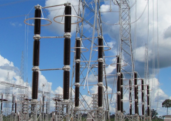
The metal oxide surge arrester is a relatively inexpensive component within a power system. Typically, it is specified, purchased and installed but often overlooked when planning condition monitoring of assets at a substation. However, an arrester is one of the key components for protection of costly assets such as power transformers and HV cables. Moreover, explosive failures involving porcelain-housed arresters present an unacceptable risk – not only for maintenance staff but also for nearby apparatus. In addition, ageing arresters mean reduced overvoltage protection, especially for older equipment and this can result in accelerated degradation of their insulation systems. Experience has shown that it is far more cost effective to replace the arrester before it fails than to deal with an unplanned resulting outage.
For metal oxide surge arresters, the best practice of risk assessment is based on the trend and level of the resistive leakage current at standard reference conditions. This edited past contribution to INMR by Hans-Ove Kristiansen and Kjetil Liebech-Lien of Doble in Norway presented cases of surge arrester assessment to prevent incipient failures.

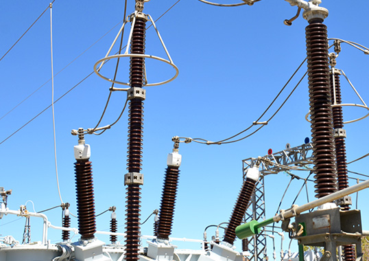
Testing 420 kV MOSAs at Transmission Utility
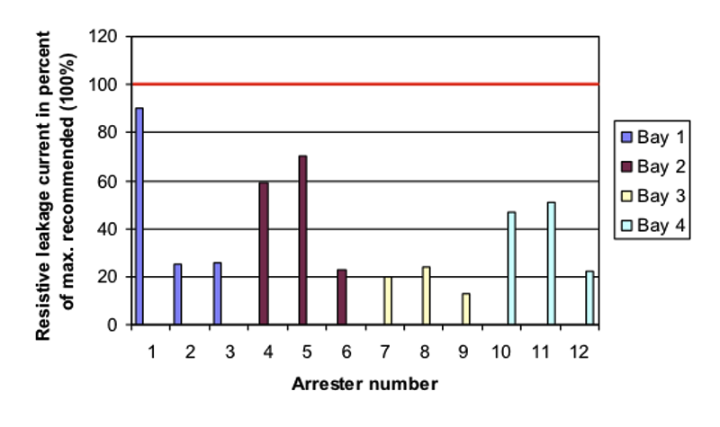
Single measurements were performed at a transmission utility on 24 MOSAs having three different brands, with results shown in Figs. 1, 2 and 3.
CLICK TO ENLARGE
As seen, seven of the arresters recorded low resistive leakage currents, i.e. around 20% of the maximum recommended level, suggesting that their condition was good. However, one arrester showed approximately 90%, i.e. several times the values of the two neighboring phases as well as the main arrester population. This unit would therefore have to be monitored closely, with frequent measurements or by continuous monitoring to check for any further increase of current. The four remaining arresters showed values of 45%, 50%, 60% and 70%. The unit showing 70% should ideally be tested more frequently, for instance every six months.
CLICK TO ENLARGE
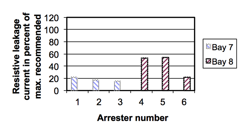
Four out of the six units presented in Fig. 2 showed readings around 20%, i.e. good condition. The last two arresters showed readings around 50 to 55%, i.e. their condition is satisfactory. New measurements should probably be performed in 1 to 2 years, depending on arrester age.
CLICK TO ENLARGE
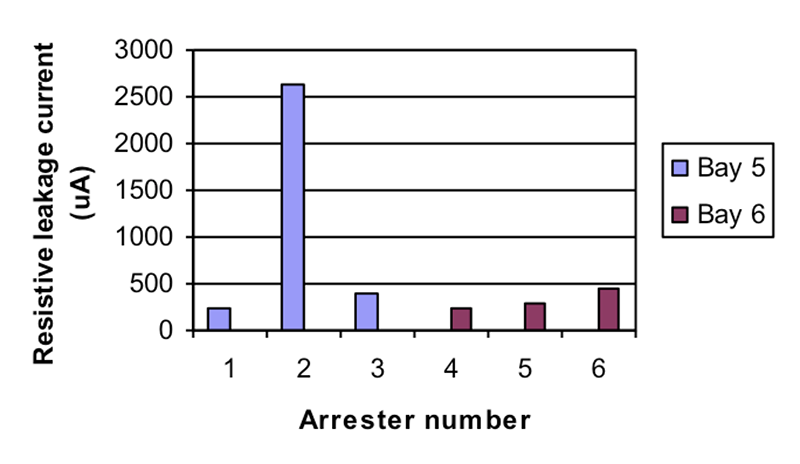
As evident from Fig. 3, one arrester showed a resistive leakage current significantly higher than the others. While no maximum recommended level was available for this type of arrester, it is reasonable to assume that the resistive leakage current should not exceed the limit of 700 µA, based on the other units. Assuming the insulated base and the insulation of the arrester earth wire are checked and found satisfactory and that there is no indication of temporary heating due to transients, the arrester should be replaced as soon as possible. The other five arresters are clearly in good to satisfactory condition.

Testing 145 kV MOSAs at Chemical Factory
This factory had six MOSAs installed at a 145 kV switching station. All were of the same make and type and first commissioned in 1984, i.e. probably as first generation designs. Since the factory is located in a coastal area, the arresters could be exposed to higher than normal pollution, which might cause accelerated ageing of their ZnO blocks. There was little to no information about their condition, except that the surge counters had not operated since 1989 and showed just a few counts. Still, the factory owner had concerns since any failure and resulting outage would cause high production losses. Measurements of resistive leakage current were performed and showed the following results (stated as a per cent of maximum recommended leakage current):
• 2 units were at around 130%
• 3 units were around 90 to 95%
• 1 unit was at 70%
Since the resistive leakage currents were in each case either significantly above or close to the recommended maximum, the factory owner decided to replace the arresters and avoid any risk of failure. The six replacement units (of the same make but of different type) were then tested after two years in service and all showed resistive leakage currents in the range of 35 to 40% of the maximum recommended level, i.e. evidence of good operating condition.

Testing Remaining 300 kV MOSAs After Failure
A transmission utility experienced a catastrophic failure and explosion of a 300 kV MOSA after about 9 years of service. Two remaining arresters were then tested with the following results:
• One unit showed 545%
• The second showed 60%.
One of the remaining arresters was clearly severely aged and therefore immediately taken out of service to avoid a second failure. The arrester was then sent for laboratory verification, which revealed that the reason for the ageing appeared to be poor coating of the blocks that caused internal partial discharges and a partly conductive surface.
Testing 110 kV MOSAs
CLICK TO ENLARGE
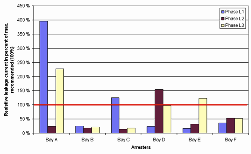
Measurements were performed on 18 MOSAs of the same type at a 110 kV substation. Two arresters had significantly higher readings (230% and 400% respectively) than the rest. The utility contacted the manufacturer and both units were removed from service and sent for laboratory testing. This showed that moisture ingress had caused internal heating and increase of resistive leakage current.

Conclusions
Leakage current measurements based on THRC have proven a reliable and efficient methodology to assess the service condition of gapless metal oxide surge arresters, in accordance with IEC recommendations. Implementing a testing strategy for substation arresters in the grid will not only optimize their lifetime utilization but also ensure that bad or aged arresters are replaced before they fail. This will contribute to increased reliability and safety while also eliminating the substantial costs associated with failure and unplanned outages.