Application of line surge arresters (LSAs) is known to be a cost-effective means to improve performance of electricity supply networks. Nonetheless, despite of their vital role in reducing lightning related outages and their help in overcoming poor grounding conditions, most utilities and transmission system operators (TSOs) consider application of LSAs only when conventional methods have not succeeded. In this regard, LSAs are often considered remedial or maintenance tools instead of as devices that can be proactively applied during the design stage of transmission lines. In fact, apart from their important role in lightning protection of overhead lines, LSAs offer several added benefits such as enhanced safety as well as control over switching surges that allow optimized structures and reduced required clearances. Their application also offers advantages in line uprating and compaction as well as during live-line work.
This edited past contribution to INMR by experts at Siemens Energy in Germany presented knowledge, experience, and innovations in achieving compact, cost-efficient and lightning-proof transmission lines.
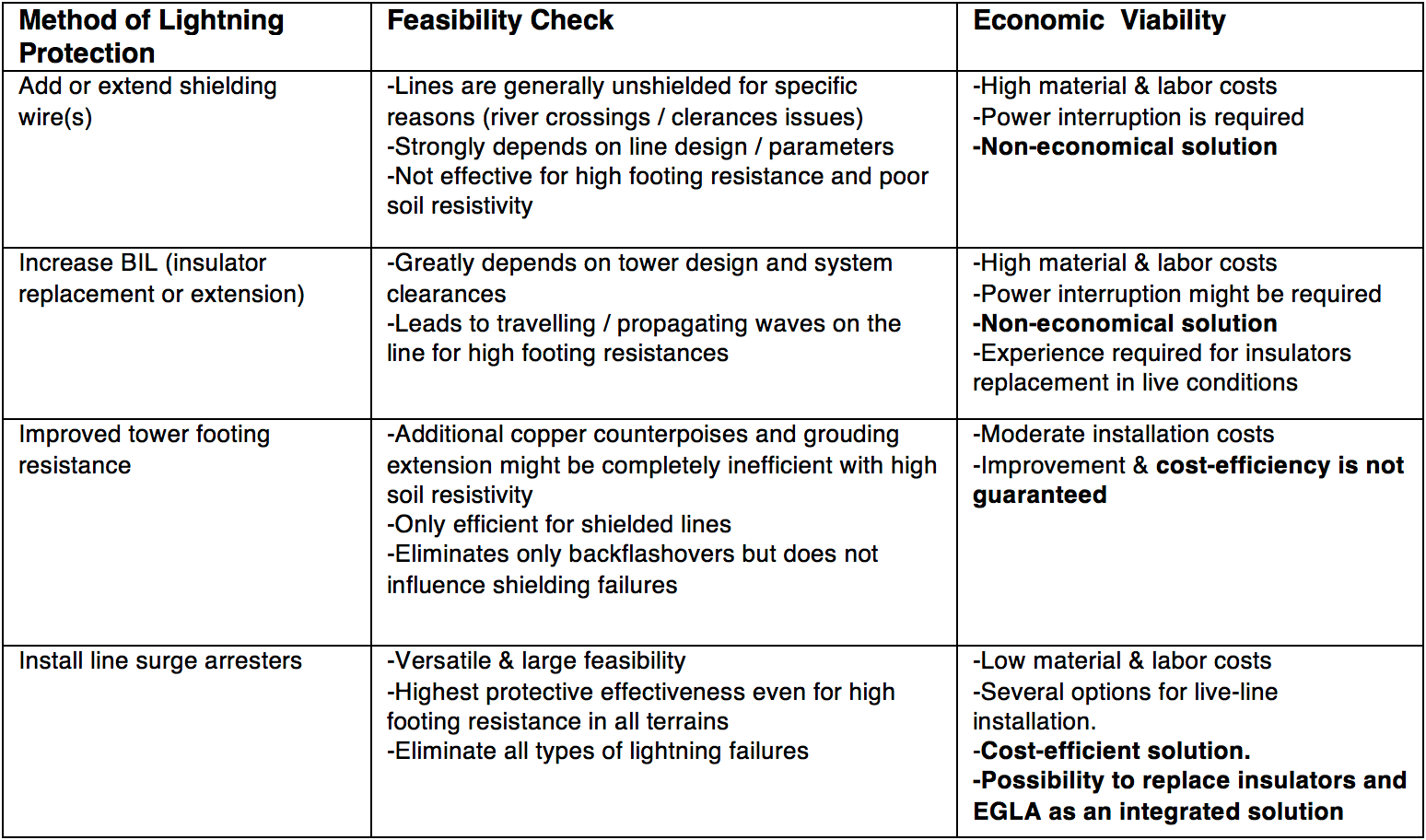
Table 1 compares alternative mitigation methods used to improve lightning performance of overhead lines.
Benefits of Line Surge Arresters
Apart from improved lightning performance, important additional benefits can be derived from application of LSAs, including:
• switching surge control to optimize structures and reduce clearances;
• assisting line uprating and compaction;
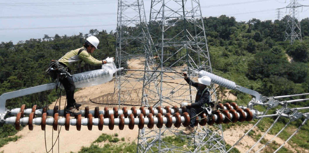
• preventing injury and damage;
• reducing minimum approach distance in live line work.
LSAs, and especially the EGLA type, therefore have still untapped potential to lower costs of line construction and operation.


a. Switching Surge Control
Switching overvoltages are typically associated with high speed reclosing on EHV transmission lines and reducing surge factors helps lower clearances and optimize transmission line design. Strategically placed, LSAs have been used in place of closing resistors and/or special switching schemes to control switching overvoltages along such lines. Moreover, unlike the case for lightning protection where arresters are installed on consecutive structures, arresters that control switching surges are needed only at specific locations along a line, usually installed on all phases. These LSAs along the line typically require one energy class less than needed for arresters installed at line ends in substations and are typically used at system voltages of 245 kV and above. Transient simulations should be performed to determine the amount of energy they must absorb.
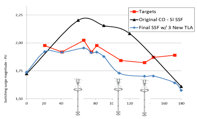
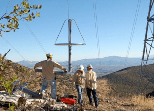
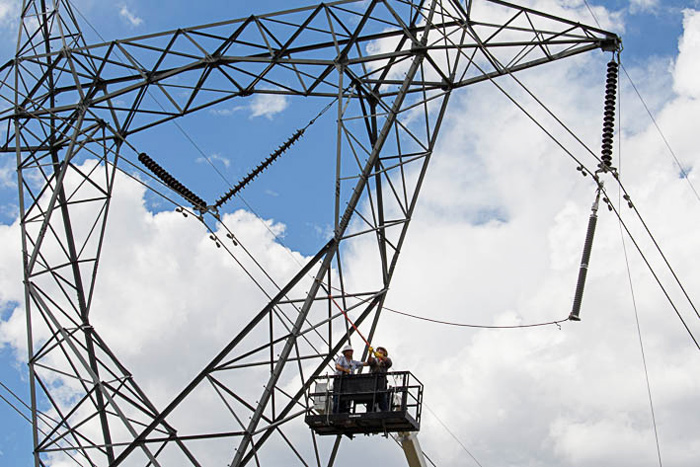
These days, with the increasing number of compact or uprated line designs, this LSA application is no longer reserved only for EHV. Moreover, even though EGLAs are the most suitable LSA type for many overhead line applications, NGLAs are preferred to control switching overvoltages. In IEC 60099-8, the external gap of the EGLA is designed and tested to withstand switching transients. However, since tolerances in gap adjustment are narrow, it is challenging to define EGLA spark gap distance to withstand power-frequency wet and guarantee operation in case of switching impulse wet. Moreover, only a few arresters at selected locations are required for switching control. Therefore, NGLAs are the better choice in such applications to avoid need to verify insulation coordination for just several units. Fig. 1a shows an example of such an NGLA application that reduced switching surge factor from 2.2 (red curve) to 1.8 (blue curve) and helped one utility make existing clearances acceptable. Fig. 1b shows live installation of NGLAs during this project.
b. Line Uprating & Compaction
There is growing demand among utilities and line designers for compact as well as uprated lines. While significant improvements have been realized in composite insulator technology, the concept has still not reached its final phase since line arresters are not always being considered to reduce clearances and decrease arcing distances. Given the growing need to build discrete aesthetic structures and, with development of composite line post and long rod insulators, compact lines have become a more realistic alternative to standard line designs. Unfortunately, even though LSAs can help optimize line compaction, most designers still do not apply this technology.
Line uprating involves increasing operating voltage and current carrying capacity of lines while retaining existing structures. However, conductor bundles as well as cross-arms and insulators strings typically must be re-designed during such modifications. This where LSAs become a highly cost-effective option to convert existing lines to higher voltages without need to change clearances, even though the insulators and hardware may need to be changed depending on RIV/corona stress performance requirements.

Line arresters help control overvoltage stresses on line insulation during both uprating and compaction projects since lightning impulse withstand level of the insulators can be reduced to the protection level of the EGLA. In this regard, the lightning impulse sparkover voltage of the EGLA gap must be lower than or equal to the lightning impulse withstand voltage of the insulator string. The EGLA’s protection level is then the maximum residual voltage when lightning overvoltage initiates a flashover on the EGLA. Once tests have been performed to verify the insulation coordination between the EGLA spark gap and the insulator assembly, flashover will occur only on the EGLA. Moreover, the EGLA’s series varistor unit (SVU) is capable of extinguishing the arc without need for operation of the line breaker.
Up to 330 kV, switching surges become a critical factor in dimensioning insulator strings and EGLAs are generally not designed to protect line insulation from such surges. Depending on system parameters, mitigation methods to reduce switching surge factors include improving station class arresters, adding closing resistors on circuit breakers or installing shunt reactors, primarily to stabilize voltage during load variations. Nevertheless, several NGLAs installed along a line are the most convenient and effective solution to reduce switching surge control, minimize EGLA gap distance on EHV systems and therefore optimize line compaction or uprating.
c. Preventing Injury & Equipment Damage
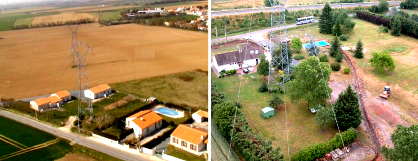
Expansion of urban areas and HV transmission systems has sometimes resulted in problems of overhead lines passing residential areas. In France, for example, EGLAs have been used since the 1990s in sensitive areas or ‘hot zones’ such as structures located near houses, factories, parking lots, etc. Their main purpose in this case has been to increase safety by significantly reducing risk of dangerous touch or step voltages due to rise in power frequency earth potential following insulation flashover. Indeed, issues of touch potential coordination become especially important when surge arresters are used on MV and HV lines in place of shield wire as the only form of lightning protection. Ground faults can then result in several kilovolts for hundreds of milliseconds.
During EGLA operation, the follow current that must be extinguished by the SVU is limited to 2 – 3A with duration of 5 to 10 milliseconds. As when improving lightning performance, due diligence starts with investigating grounding quality as well as configuration of shield wires. Conventional methods are often costly and ineffective, and engineers have increasingly come to recognize the advantages of applying EGLAs, given their compact design and high reliability. French utilities, for example, adopted EGLAs for safety concerns as well as improved lightning performance. Results over a 20-year period have proven positive with respect to long-term reliability, reduction in outages and improved safety. Moreover, there is added potential to also use LSAs to mitigate risk of gas pipeline failure from lightning strike and to protect IT facilities from electromagnetic disturbances due to insulator flashovers.
d. Live Line Work: Temporarily Reducing Minimum Approach Distance
With live work now an established part of routine maintenance at utilities, a continuing concern is ensuring that work sites are not exposed to unacceptably high overvoltages. Some utilities use a portable protective air gap (PPAG) to limit overvoltages at sites of energized work but these come with several disadvantages. EPRI in the U.S. has therefore begun investigating use of LSAs instead since these offer enhanced protection for live line workers, providing of course that there are practical ways to ensure arrester integrity prior to and during such maintenance.
Regular insulation tests on the active part are not relevant in this case since the MCOV has to be applied to properly assess its condition. NGLA type LSAs are preferable in such applications since the main safety goal during live line work is to protect against switching overvoltages. Energy rating requirements that are specific to each line and work site must be accurately defined so as to optimize arrester weight, which is important when it comes to handling and installing it on the line. The NGLA is connected from phase conductor to tower and crest value of any possible overvoltages at the work site is determined by arrester rating and its residual voltage of protection level in relation to protection distance. This arrester solution offers the advantage that its operation is not associated with a power arc, as is the case for a PPAG. This minimizes risk of exposing workers to power arcs. Installation of arresters on all phases on structures adjacent to the work site (the site structure itself not being equipped with LSAs) may be sufficient to protect workers depending on surrounding grounding conditions. Line arresters in this application should be used without a disconnector for enhanced worker protection.
e. Reduced Costs & System Losses
Poor grounding conditions linked to rocky soils and areas with high soil resistivity make it difficult to achieve good lightning performance. EGLAs can be used effectively in such cases to replace costly and often ineffective additional counterpoises and grounding extensions. Simulations can then guarantee EGLA performance below a certain measured footing resistance with reasonable safety margin. EGLAs can even be integrated into insulator strings to simplify work and mounting. Cost savings linked to this solution can be significant but are often underestimated. For example, one U.S. study by an independent expert demonstrated that installing EGLAs on each tower and every phase in place of overhead ground wire (OHGW) not only significantly reduces capital cost of construction but also results in lower transmission line losses. Unfortunately, most utilities and line contractors still look only at traditional solutions since shield wires and OHGW are often required in a project’s specification and lightning strokes risk physically damaging phase conductors. Nevertheless, the cost savings linked to applying EGLAs instead are impressive and line designers still have solutions to reinforce conductor design and install optical fibres at different locations.

Comparison of Application: NGLAs vs. EGLAs
The non-gapped line arrester (NGLA) is basically an adaptation of the substation arrester used to protect valuable assets such as power transformers. The active part is directly connected between phase conductor and grounded structure and the residual voltage of the MCOV column limits overvoltages across the insulators to prevent flashovers should BIL be exceeded. An NGLA installation requires a clamping system to the conductor, a ground lead disconnector (GLD) and, in most cases, grading with corona rings. Mechanical and mounting considerations are an essential step in design of NGLAs, which are generally installed under harsher service conditions than arresters at substations. In fact, the complete assembly is permanently stressed over its service life. NGLA installation is such that the unit is allowed to move freely due to wind and/or line swinging and vibration. Users and manufacturers must therefore pay special attention to avoid premature mechanical failures. Moreover, a disconnector is installed in series to electrically isolate the arrester from the line in the unlikely event of fault or thermal overload. This automatically and immediately disconnects the LSA from voltage and thereby allows the affected line to be re-energized and operated until replacement of the unit can be scheduled. Relevant standards governing these items are: IEC 60099-4 / IEEE C62.11 Application Guide IEC 60099-5 / IEEE C62.22, and IEEE 1243 (lightning performance improvement).
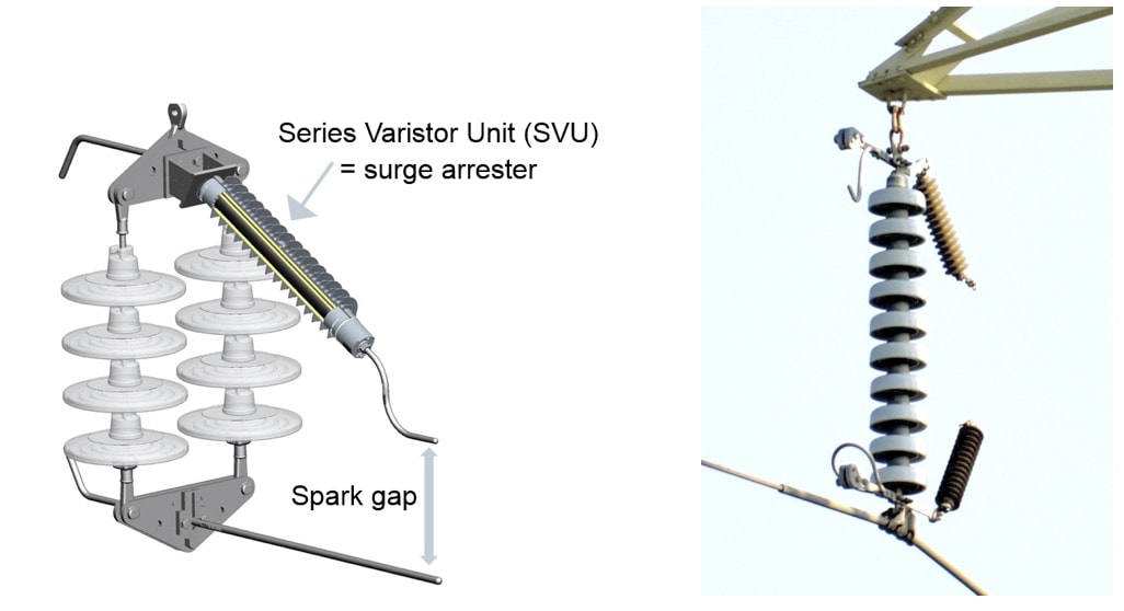
Externally gapped line arresters (EGLAs) have an external spark gap placed in series that isolates the active series varistor unit from line voltage under normal conditions. In case of lightning, the spark gap is ignited and the overvoltage is safely discharged through the resulting arc. The active component, the SVU, limits subsequent current to ensure that the arc is extinguished within the first half-cycle of operating power-frequency voltage. After this, the LSA immediately returns to standby condition. No breaker operation is required as part of this process and the LSA’s active component can have either one or two SVUs (on each side) depending on system voltage level and user requirements. The relevant standard is IEC 60099-8.

Advantages of EGLA Application
a. Material
Less material is needed to design an EGLA and the metal oxide varistors can have smaller diameters since its energy handling requirements are lower than for an NGLA. Moreover, the EGLA does not handle TOVs and switching overvoltages, which are not relevant in lightning performance. Rated voltage (Ur) of an EGLA has a different definition than in the case of typical rated voltage for an NGLA application, i.e. Ur of the EGLA represents the maximum phase-to-ground voltage to be extinguished safely during the follow current interruption test.
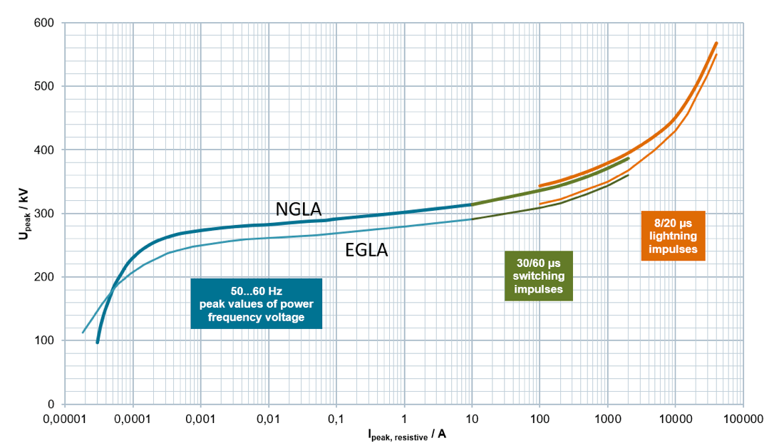
This means that fewer MOVs are required compared to an NGLA design where Ur represents temporary overvoltage (TOV) with prior duty. Fig. 7 compares the Voltage-Current characteristics of a 192 kV rated NGLA and EGLA and shows that the EGLA’s protection level always has lower residual voltages. Additional hardware such as supports and counterweights might be required for certain retrofit applications of EGLAs if existing insulator strings do not allow easy installation. In the case of new transmission lines, however, ‘smart’ integration of EGLAs from the start makes this solution compact and highly cost-effective since need for additional retrofit hardware is eliminated. EGLAs are specifically designed to improve lightning performance whereas NGLAs are an easy solution to cope with station class arresters that are not optimized. In most cases, NGLAs require a clamping system to the conductor, a ground lead disconnector and grading rings.
b.Cost
As discussed above, less material in the case of EGLAs means lower costs since MOV, FRP and silicone rubber materials as well as hardware and accessories can either be reduced or even eliminated. Significant cost savings can be achieved depending on final design of mounting hardware and the higher the voltage the greater will be the reduction in costs. Moreover, many utilities also report lower installation costs since EGLAs can be pre-assembled together with insulator strings. Operating and maintenance costs are lower as well due to the reliability and long-term stability of the EGLA design.
c. Electrical Performance & Long-Term Stability
The protection level (residual voltage) of an EGLA is always better than for an NGLA since less MOVs are required due to the air gap that isolates the SVU from the system under normal operation. Therefore, the MOVs are not continuously under voltage and there is neither leakage current nor electrical stress. Better ageing performance and longer life are therefore expected. Japanese utilities, for example, have had EGLAs installed on their networks for more than 25 years and report that these are still in good condition.
d. Installation
The weight of a complete EGLA solution is typically lighter than for an NGLA. The SVU can also be pre-assembled on the ground on insulator strings (or directly on towers) to simplify installation, which generally does not require helicopters or cranes as typically needed for NGLA installation. Proximity to the insulator simplifies final EGLA configuration and guarantees proper installation. A range of options exists for live installation in the case of retrofitting existing lines. Pre-assembly of the complete set (EGLA + insulator + hardware) can even be prepared by the supplier to optimize lifting and mounting time while also reducing risk of missing components.
e. Maintenance / Operation
Basically, no maintenance is required for EGLAs and failure rate is extremely low. If properly designed and installed, these can be considered as reliable as the standard components in insulators strings. Moreover, no specific monitoring is required apart from the regular overhead line inspections already being performed and which allow failed SVUs to be easily identified visually. One of the keys to performance is that the EGLA design must be rigid and stable, with no moving parts accepted. By contrast, the ground lead and mechanical stress under vibration and galloping reduce the reliability of NGLAs. High EGLA resistance to vibration and mechanical stress from seismic activity can also be demonstrated. Furthermore, failure of the SVU does not influence continuous operation of the line due to the gap that isolates it from the system. This means there is no immediate need for replacement. In addition, EGLAs cannot fail due to line faults and the gap is dimensioned to withstand both power frequency and switching overvoltages.
Worldwide Application of EGLAs
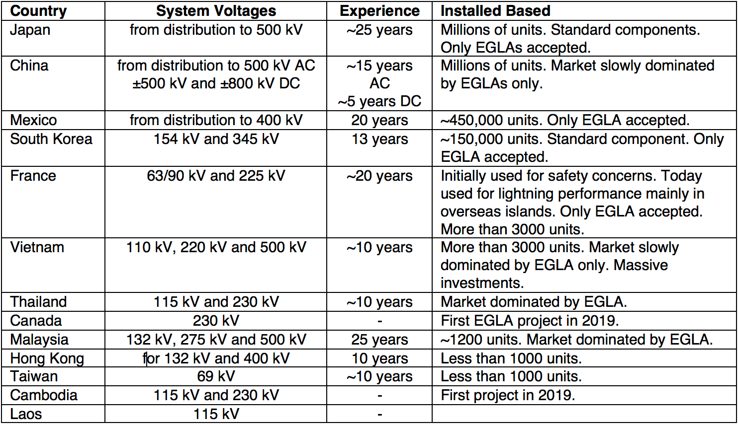
While global application of EGLAs is not new, it might nonetheless be termed a ‘new application’ since their outstanding features are still not widely known and utilized. By contrast, the countries shown in Table 2, with some exceptions, only accept EGLA application on their networks with use of NGLAs not accepted due to concerns about reliability and long-term performance.

Conclusions
The electricity supply industry is conservative by nature and new technologies therefore tend to be adopted progressively in stages rather than wholesale adoption across the entire network. Over the past decades, growing industry attention has been devoted to reducing lightning outages. LSAs are now a topic of growing interest and attention since they not only improve performance and operation of power systems but also allow optimized design and lower costs of construction as well as maintenance. These economic benefits are easily demonstrable and better synergy between line designers and arrester manufacturers will only help expand shared knowledge and experience. For their part, arrester manufacturers should make users more confident about long-term reliability since it is one of the main concerns for utilities and their customers. Similarly, it would be beneficial for grid operators and utilities to better communicate results and experience from their own mid-term assessments. The opportunities and the advantages offered by LSAs are significant when it comes to line uprating and compaction but unfortunately these applications are still underutilized because engineers need to redefine ratings that have applied for the last century.
Currently, IEC 60099-4 or IEEE C62.11 governing NGLA applications do not draw a clear distinction between Line Surge Arresters and Station Class Arresters in term of energy handling requirements and mechanical considerations. Nor is there yet an IEEE Standard that addresses EGLAs. Moreover, the latest IEC 60099-8 EGLA Standard has two energy classifications, neither of which is sufficient to clearly define energy performance. These issues will hopefully be resolved with release of IEC 60099-11 that will cover both EGLA and NGLA applications.
References
[1] J. Woodworth: “Lowering Losses on Transmission Lines Using Arresters”, CEATI’s 6th Annual Grounding & Lightning Workshop, Niagara Falls, October 2014.
[2] J. Woodworth: “The Externally Gapped Line Arrester – A Design and Application” and “Guide for Condition Assessment of Lightning Arresters installed on Transmission Lines”, CEATI’s 8th Annual Grounding & Lightning Conference, Arlington, USA, November 2016.
[3] J. Woodworth: “Benefits Justify More Use of Transmission Line Arresters”, INMR.com
[4] U. Bauch: “Line Arresters – Live Insurance Of The Grid – Trends & Developments”, INMR World Congress, Munich, October 2015.
[5] P. Bunov, L. Klingbeil, D. Udovcic and D. Biswas: “Externally Gapped Line Arresters – First experience with the new IEC 60099-8 standard and Line study analysis”, IEEE Power & Energy society transmission and distribution conference and exposition, Orlando, Florida, USA, May 2012.
[6] P. Bunov, L. Klingbeil, B. Goßler and L. Montaz: “Design and Testing of a 225-kV Externally Gapped Line Arrester for installation under live conditions”, CIGRE C4 International Colloquium on Lightning & Power Systems, Lyon, May 2014.
[7] R. Göhler, L. Klingbeil, M. Schubert: “Surge Arrester design and testing experiences according to the new IEC 60099-4”, CIGRÉ International Technical Colloquium, Rio de Janeiro, Brazil, September 2007.
[8] L. Klingbeil, Z. Baus, S. Nikolovski, I. Ivankovic: “Case Study for Application of Transmission Line Arresters at Croatian 400kV Line along the Adriatic Coast Mountains”, CIGRÉ Colloquium on Application of Line Surge Arresters in Power Distribution and Transmission Systems, Cavtat, May 2008.
[9] CIGRE 440 – Working Group C4.301: “Use of Surge Arresters for Lightning Protection of Transmission Lines”, December 2010.
[10] F. Bologna and C. Engelbrecht: “Mitigating Transmission Line Arrester Lead Stresses”, INMR World Conference, Munich, October 2015.
[11] V. Hinrichsen: “Overview of Recent Technological Developments for HV Line and Station Arresters & Future Tendencies, INMR World Conference on Insulators, Arresters and Bushings, Rio de Janeiro, May 2007
[12] S. Page: “A Comparison of Commercial Lightning Software”, CEATI’s 8th Annual Grounding & Lightning Conference, Arlington, USA, November 2016.
[13] KEPCO: “Seminar for Transmission Line Arrester”
[14] Mitigating Ground Potential Rise on Towers & Improving Electricity Quality Using Line Arresters, Frederic Maciela, INMR
[15] CIGRE B2 TF 007, “Interaction of vibration dampers with surge arresters,” October, 2016.
[16] Private discussion with EPRI.
[17] 10 YEARS OF FIELD EXPERIENCE WITH EGLA TYPE LINE ARRESTERS AT THE COMISION FEDERAL DE ELECTRICIDAD (CFE), INMR 2018, M.I J. Gerardo Montoya Tena
[18] Arrester Technology Improves Transmission Line Performance: Experience in Malaysia, INMR 2017, Iryani Mohamed Rawi