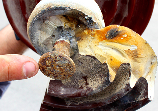
Power utilities occasionally face outages caused by de-capping of porcelain cap & pin strings – a process whereby the porcelain body separates from the insulator head. The principal mode of failure in this case is dielectric puncture, defined as a disruptive discharge through the body of a solid dielectric and resulting in permanent loss of dielectric strength. This edited past contribution to INMR offered advice on how best to test for and mitigate such risk.


Primary insulation in ceramic cap & pin insulators is provided by the porcelain sandwiched between end fitting hardware. Given that the inter-electrode distance is shortest here, this region of the insulator is subject to much higher electrical stress than other parts. Puncture is evaluated using standard methods, as per ASTM or IEC, whereby thin sheets of the material being tested are placed between spherical or plane electrodes and exposed to power frequency voltage. The sample is immersed in oil to ensure that any discharge occurs inside the material and not across its surface.
The typical value of dielectric strength for ceramics is quoted in the literature at 15 kV/mm – a value mainly of academic interest since most insulators employ thicknesses in the range of 15-25 mm for each bell. This means that they are subject to comparatively low electric stress compared to their inherent dielectric strength.

The standards have required the puncture test be performed as a sample test for insulators at time of manufacture. Generally, more than 110 kV is required to cause puncture in a new insulator while, depending on its position in the string, the voltage across each bell varies from only 5 to 20 kV. The question then arises, what causes porcelain to puncture at electric stresses far below the strength measured in the new condition?
Electrical grade porcelain is made by firing a heterogeneous mixture of ingredients and therefore contains numerous pores and interfaces. While there is a test for porosity in industry standards that is performed on sample insulators when manufactured, this test will not provide any indication of their internal condition after they have been in service for years. Indeed, punctures have been known to occur 15 or 20 years after an insulator has been placed in service.
Other factors are also responsible for insulator puncture beyond composition and firing details during production. These include magnitude and duration of 50/60 Hz overvoltages, lightning and switching surges, mechanical vibration and environmental conditions. It is therefore difficult to predict if and when insulators will puncture during service.

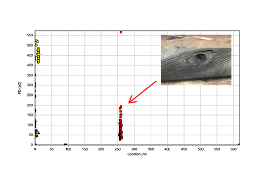
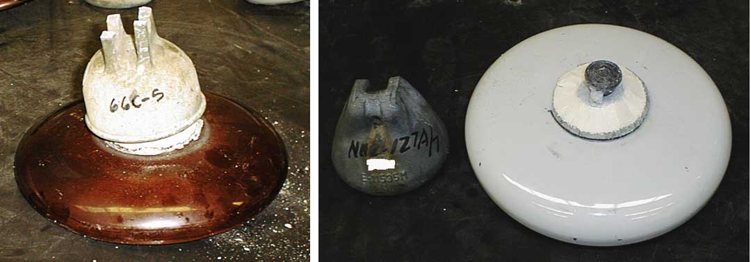
Once a puncture does occur, its path can involve either a single or multiple partially conducting channels. These paths grow gradually and in many instances never completely bridge the distance between the cap and the pin. Hence resistance measurements on such insulators can vary over a wide range. For example, good porcelain bells have internal resistance in the range 1010 to 1012Ω. By contrast, defective porcelain bells are known to yield values over a wider range (i.e. 0 to 108Ω), depending on the extent and nature of the defect.
From the viewpoint of live-line maintenance, even a few defective units in a string can be tolerated. The chief reason for this is that such work is almost always carried out under fair weather and it is also possible to assess the actual number of sound units prior to start of maintenance. For example, at 69 kV the number of permissible defective units in a string is one while in the case of 765 kV this increases to as many as 10. However the presence of even a single defective unit can cause catastrophic failure (line drops) should there be flashover. The resulting power follow current is fairly high (several hundred Amperes) and its path depends on the insulator’s internal (i.e. body) and external (i.e. surface) impedances.
On sound units, internal impedance is much higher than the external value. This causes the current to flow along the surface of the bell. On defective units, however, the current divides and part of it flows inside the bell. It is this internal current and the great electromechanical forces it generates that cause the porcelain to separate from the cap. External impedance is hard to determine since it depends on thermal ionization (which is a function of arc temperature), moisture (e.g. relative humidity, rain, dew) and contamination. With so many variables involved, it is not surprising that in some locations strings with defective units are able to function normally whereas in other locations there are line drops.

It helps to keep tower footing resistance to a low value (e.g. by using counterpoises) since de-capping seem to be more prevalent in areas with high lightning intensity. However, the real source of the problem lies in the quality of the porcelain body, which can vary significantly from one manufacturer to another. A steep front impulse test (as in IEC 61211) is a good way to evaluate the integrity of the dielectric although it is not always evident whether or not this test can identify poor quality insulators at time of manufacture. Still, if not found in user specifications, it would be prudent to include such a test as well.
A more practical way for users to overcome the problem is as follows: whenever there is scheduled maintenance, remove those units that have been in service for varying periods of time and subject them to resistance measurements, steep front impulse, thermal-mechanical testing, etc. A database can then be created listing test results along with supplier and year of manufacture. This way, a power utility can determine if the problem is manufacturer specific or rather generic.
With modern demand for high reliability, timely identification of defective porcelain insulators that are approaching puncture is becoming critical and this cannot be done by visual inspection alone. There are several suitable instruments for this purpose and their sensitivity increases as the defective insulator’s condition approaches short circuit. Unfortunately, since this is rarely the case, experienced, well-trained personnel are needed to correctly interpret test results.