There are only a few installations worldwide whose purpose is to assess performance of different designs of line hardware and conductors under stresses caused by environmental factors such as wind and icing. One of these, operated by Hydro-Québec, is located in a flat agricultural region south of Montreal.
In 2018, INMR visited this installation and also the related conductor and hardware test facility at the nearby Institut de recherche (IREQ).


Hydro-Québec’s transmission system consists of over 34,000 km of lines of which about a third operate at 735/765 kV. Indeed, this was the first network in the world to rely so extensively on 735 kV lines to link hydroelectric power in the province’s distant northeast with key demand centers in Montréal and Québec City.
Given the vast scale of this power grid and the typically severe wintry conditions to which it is exposed, testing different conductors and related line hardware such as dampers and spacers has always been a priority. In the past, this work was performed at a facility located on the windy Magdalen Islands at the mouth of the St. Lawrence River. Then, in 1991, testing was relocated to a special line in Varennes, only minutes from Hydro-Québec’s major research and testing institute.

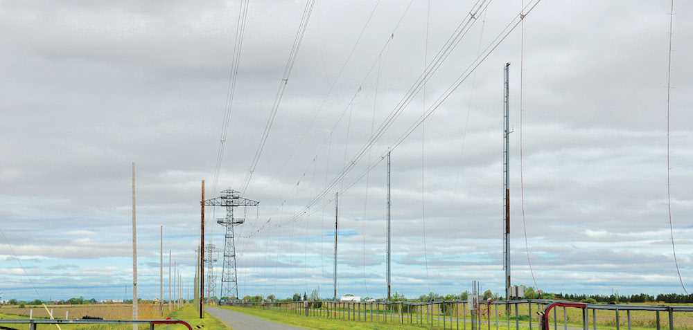
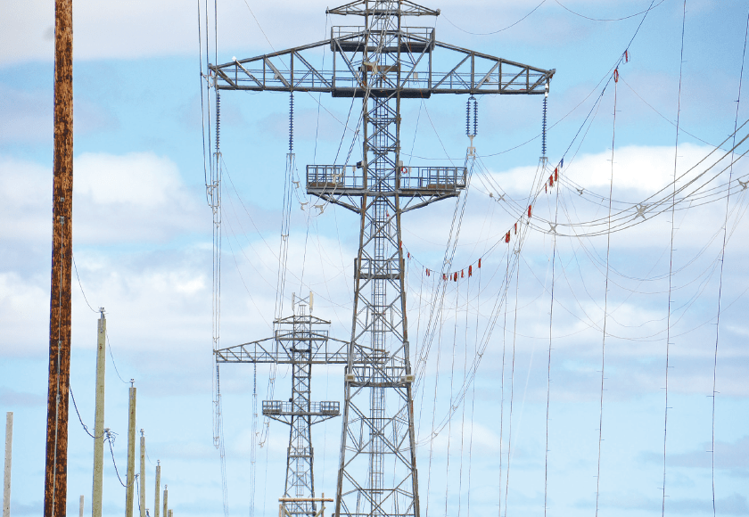
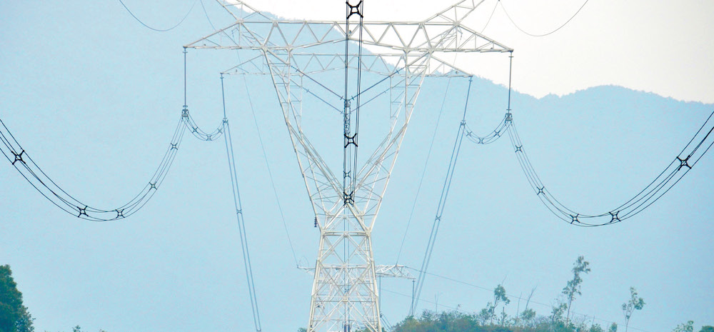
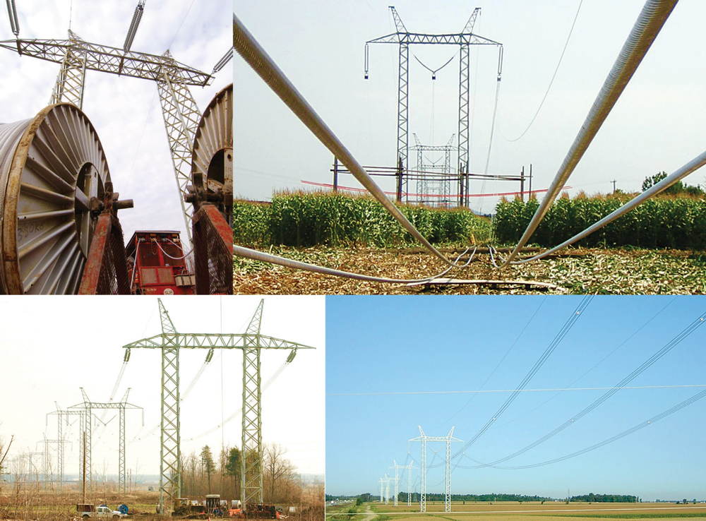
Pierre Van Dyke, a Sr. Scientist in the group charged with such testing and also active in the related CIGRE Working Group within SC 22 (Overhead Lines), explains that the 1.575 km test line consists of five spans – three suspension and two dead-end.
Distances between suspension towers vary from 400 m to 450 m, the latter being the average length of the spans used on the Hydro-Québec transmission network. Van Dyke also points out that the test line has been refurbished twice over the years with all the former gauges replaced by a new data acquisition system as well as centralized computer control.
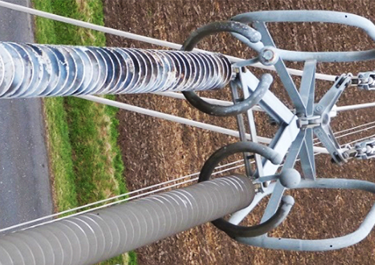
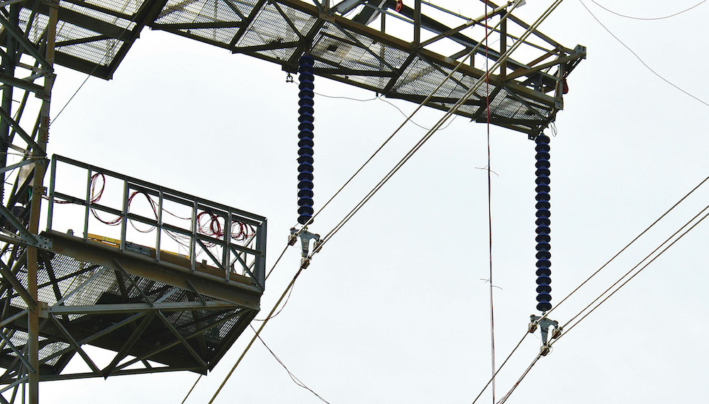
The basis for selecting four suspension towers was to reproduce a typical line section with three suspension spans, where most conductor problems such as strand failure from fretting tend to occur. This is also where dampers and spacers play a critical role in minimizing such damage. Says Van Dyke, “spacers and spacer dampers not only maintain the geometry of conductor bundles under normal service conditions but the use of unequal subspan lengths (distances between spacers or spacer dampers) will reduce the susceptibility to subspan oscillations. Spacer dampers also dampen Aeolian vibrations by allowing the energy to be dissipated.”
Van Dyke explains that three anemometers positioned on poles along the middle span monitor the wind speeds that actually impact conductors and line hardware. The horizontal wind flow will generate vertical aeolian vibrations due to alternate shedding of vortices from the top and bottom sides of the conductor. The test line site is also equipped with a full-fledged weather station that records not only wind velocity, azimuth and turbulence but also meteorological variables including barometric pressure and air density. Such information is then readily available depending on the data needs of any particular research project.

Our facility is unique in the world,” reports Van Dyke. “Although there are test sites in Japan devoted to study of galloping, here we are able to also work on other phenomena, from Aeolian vibrations to low frequency sub-span oscillations that lead to conductor clashing. Such oscillations not only risk damaging conductor strands but also impact articulation of the spacer dampers.”
Other phenomena studied at the Varennes test line site include galloping and ice shedding. In the former case, Van Dyke states that special plastic sleeves have been applied over conductors to simulate ice accretion and that these can have steel rods inserts to represent heavier ice loading. Such testing is devoted mostly to studying performance of interphase spacers.
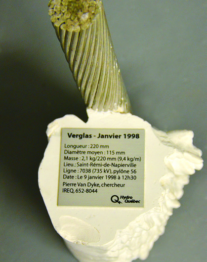
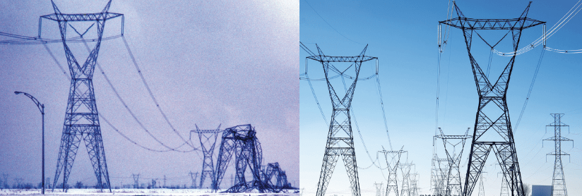
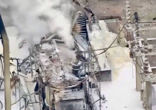
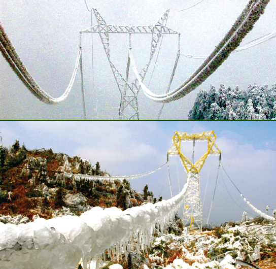
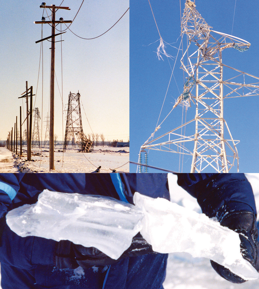
Ice accretion on conductors, combined with high winds, were cited as the main factors in one of the most important events affecting Hydro-Québec’s network – the massive ice storm of January 1998. Hundreds of transmission structures toppled and millions were left without power, some for many weeks. This was one of the formative events in the utility’s history and spurred large volumes of research on how best to avoid such calamities in the future.

c
Ice shedding induces high dynamic loads on conductors and utilities such as Hydro-Québec want to learn more on how selective application of spacers can prevent phase-to-phase flashovers from this phenomenon. Van Dyke explains that such testing sees one conductor installed on the test line while another is attached on the same conductor just below it using ropes along the span. Release of the dead weight conductor breaks the attaching ropes along the span and simulates the impact of ice breaking off.
Apart from studying weather phenomena that impact conductors, another example of the type of research project carried out is assessing the impact of stringing operations on hardware such as suspension clamps. According to Van Dyke, it is not uncommon that line workers leave conductors extended on pulleys for prolonged periods, especially if shifts end before a weekend or other holiday. Here, the goal was to verify if conductor life is adversely affected from having remained too long under such loading without spacer dampers or dampers protection.
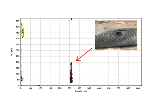
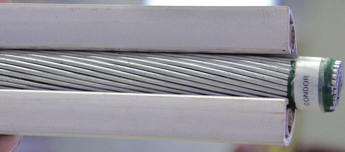
Van Dyke points out that conductor service life is typically the main criterion in the economic life of an overhead line. “At voltages above 69 kV,” he remarks, “conductors typically account for between 40 and 50 percent of the total cost of a new line. Therefore there is always great interest to establish a conductor ‘health index’ and, recommend actions such as conductor replacement, conductor repair or no action required.
In order to maximize utilization of the facility, tests are also undertaken on behalf of manufacturers of different line hardware – an activity that Van Dyke notes offers the added benefit of also increasing local expertise. For example, during the 1990s Van Dyke and his team developed a proprietary damper design that he says will not break under stresses from ice shedding or galloping.
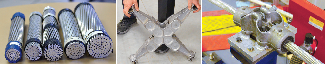
Similarly, about a decade ago a new type of suspension clamp was developed with funnel-shaped elastomers at the ends. The rigidity of the clamp is reduced gradually, explains Van Dyke, and this minimizes bending of the conductor under galloping or Aeolian vibrations. The clamp comes in a range of diameters and is now the only one used on all new lines within the Hydro-Québec system.
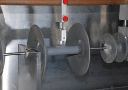
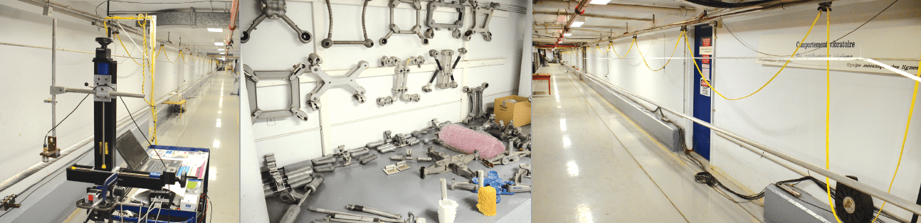
Apart from the exterior test line, Van Dyke and his team also have access to indoor facilities where items such as clamps and spacers can be tested under controlled cycles of stresses. A 7 m test span, for example, creates vibrations of given amplitude and line hardware is tested for up to 500 million cycles over a 4-month period, as required by IEC standards.
The new suspension clamp design was tested here against a metal-on-metal version and Van Dyke reports that the former offered much improved performance, especially under galloping, which in this case is the greater concern than Aeolian vibrations.
Another laboratory offers an indoor span of 63.5 m. Here, the end span supports are anchored to the bedrock to obtain maximum stiffness and minimize vibration losses. Says Van Dyke, “this span allows measurement of inherent conductor damping against the vibrations we create versus those triggered by wind. Since we fully control amplitude and frequency of vibration, we can test performance of both the conductor itself and of the dampers.”