The geometry of a transmission tower must accommodate different electrical clearances under varying weather conditions, as provided for in national standards or codes. In this regard, substantial consideration must be given to switching surge clearance and minimum approach distance, both of which depend on switching surge overvoltage level of the line. A lower switching surge overvoltage can lead to more compact tower top geometry, which in turn can reduce total project costs as well as overall environmental impact.
This edited past contribution to INMR by C. Wang, J. Kell and W. Chandrasena of Manitoba Hydro presented a novel method to optimize structure design based on application of transmission line surge arresters.

Manitoba Hydro’s electrical system depends on power generated by hydraulic generating stations in the north whose output is transferred southward hundreds of kilometers along three HVDC lines. This HVDC system carries about 70% of the Province’s total generation supply. In the event of extended drought or an HVDC outage, supply becomes restricted to generation connected to Manitoba Hydro’s AC system, which relies on AC interconnections with the United States and neighboring provinces. But such a restricted supply of power would be inadequate to meet provincial demand and could necessitate rotating blackouts for months. The potential shortfall has been growing steadily over the years and, given growing power demand, system load requirements have increased.
The Manitoba-Minnesota Transmission Project (MMTP) was the province’s second 500 kV AC line connecting to the U.S. power grid. This transmission line runs 575 km and connects Dorsey Station in Canada to Iron Range Station in the United States. The objective of the project was to deliver contracted power supply to the U.S. and also to ensure reliable energy supply to Manitoban customers in the event of prolonged drought or unforeseen equipment failures.
The first 500 kV international power line in Manitoba – M602F – was designed during the 1970s. Based on design and weather information at the time, a minimal approach distance (MAD) of 10 feet was used at all locations. Two safety incidents have since been recorded during live line work on towers and live line maintenance is therefore currently not permitted at structure window locations along this line.
The MMTP has 60% series compensation to maintain a 2000 A continuous current rating and this 1440 MVar series capacitor was among the world’s largest at 500 kV. This size of series capacitor combined with long line length results in very high switching surge voltage, affecting both tower design and future live line maintenance. To address this, Manitoba Hydro conducted a detailed switching surge study to help optimize design of the line’s towers.

Switching Overvoltage Analysis
PSCAD studies confirmed that the large series capacitor rating and line length would result in high switching surge voltages and require significantly larger phase-phase and phase-ground spacing as well as wider right-of-way. This would make it nearly impossible to utilize portions of existing right-of-ways identified for this project. For example, results showed that a typical series capacitor design with a bypass breaker (i.e. the least cost solution) would result in a 3.5 p.u. switching overvoltage and violation of breaker TRV. Simulation studies also showed that a special series capacitor design with fast bypass and an external damping resistor could mitigate higher breaker TRV and maintain switching overvoltage below 3.0 p.u.
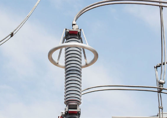
Transmission line surge arresters (TLSAs) are designed to limit voltages between phase conductors and tower structure and prevent flashover. Initially designed to mitigate outage rate due to lightning on transmission lines, TLSAs have been applied in North America for many years and shown excellent results. More recently, TLSAs have also been applied to limit high switching overvoltages. However, unlike for lightning related applications where arresters might typically be installed on consecutive structures, arresters to control switching surges are needed only at specific locations along a line and installed on all phases at these locations. Moreover, these arresters typically require one energy class lower than what is needed for arresters installed at line ends in substations.
Transient simulations confirmed that a compact transmission line tower that matches current limits of approach for live-line maintenance, namely 2.5 p.u. voltage, can be built assuming high switching surges are mitigated using TLSAs along with design enhancements identified for the series capacitor. As a result, Manitoba Hydro engineers recommended TLSAs for application on the new 500 kV line to mitigate high switching surge voltages and facilitate future live-line maintenance work.
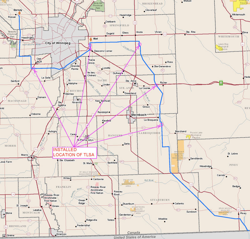
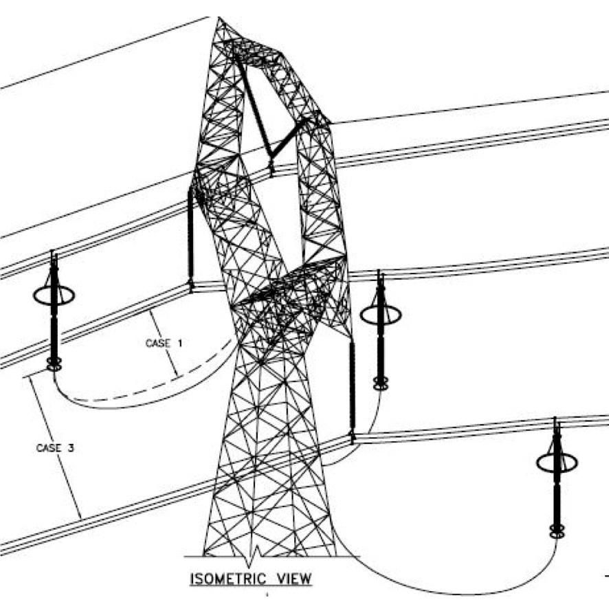
Five locations out of the line’s total 524 towers were selected for surge arrester installation and numerous PSCAD simulations were performed to determine these locations (see Fig. 1).

Tower Top Geometry & Right-of-Way
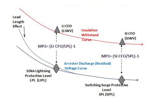
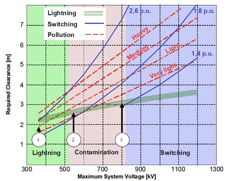
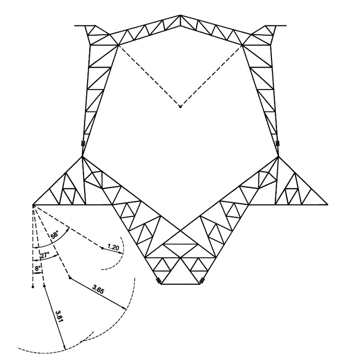
Tower top geometry is designed to meet all required electrical clearances based on internal and external standards and determined primarily by: power frequency voltage; switching overvoltage; and lightning overvoltage. As shown in Fig. 2, if switching overvoltage is limited to about 2.0 per unit for 500 kV system voltage, clearances required for lightning and switching overvoltage are almost the same. However, most 500 kV systems have a switching surge factor larger than 2.0 p.u. and switching surge overvoltage is therefore the dominant factor in design of tower top geometry. Moreover, in the case of the MMTP, clearance under power frequency voltage was not deemed a governing factor due to the light pollution in Manitoba. Thus, tower top clearance was governed mainly by switching overvoltage.
The tangent suspension insulators commonly used on transmission lines are subject to swing due to wind. Sufficient clearances between the live end of the insulator string and any grounded component of the support structure must be maintained to provide safe and reliable operation of the line under wind. Based on past studies and review of historical meteorological data, three wind conditions were considered in design of the MMTP tower top geometry. The first was a high wind condition, expected to occur only rarely while the system is under power frequency voltage. The second was moderate wind, assumed to coincide with a switching surge overvoltage. The last was a nominal wind condition, expected to occur frequently and therefore most likely to coincide with live line work.
All wind conditions were applied only to I-string insulators at cross-arm locations since V-string insulators, within tower windows, were assumed to have limited movement during these wind conditions. CIGRE Technical Brochure 348 discusses how to ensure adequate clearance and prevent flashover between conductors and structure during still air as well as swing positions. High wind is defined as the 50-year return period design condition which will rarely occur while the system is under power frequency voltage only. The moderate wind condition is defined as wind pressure during 99% of the time (CIGRE 1%), i.e. the insulator string is exposed to this type of wind condition frequently enough to coincide with a switching surge overvoltage. The 40 km/h wind condition is defined as the maximum wind speed during which live line procedures can be safely executed by qualified personnel.
Switching surge clearance and MAD both depend on maximum switching surge factor of the system. As mentioned, there were three possible switching surge factors based on different system configurations. Table 2 summarizes the electrical clearances required for switching surge voltage and MAD.
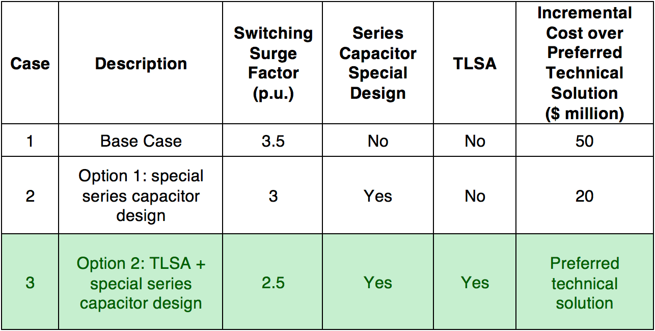
A higher switching surge factor would require larger electrical clearance and wider tower, which was likely to be more costly. To further examine each design, three different designs of tower top geometry were created in PLS-TOWER based on different switching surge factors. The most compact tower design would be based on a 2.5 p.u. switching surge factor, which is set as the base case due to it being of lowest cost.
In addition to higher material costs, a wider tower usually requires wider right-of-way (ROW). Several factors influence ROW width for a transmission line including conductor swing out, audible noise, electromagnetic field, etc. Detailed analysis indicated minimum ROW widths of 80 m, 86 m and 92 m respectively required for 2.5, 3.0 and 3.5 p.u. switching surge factors. Significant land would be required for tower designs using a higher switching surge factor. For example, in Manitoba, a 3.0 p.u. switching surge factor would require an additional 316 acres while 631 more acres of land would be needed for a 3.5 p.u. switching surge factor.
Nearly 50% of the MMTP line traverses existing Manitoba Hydro owned 80 m wide ROW and any increase in land requirement would significantly impact overall project cost. Moreover, a wider ROW is less eco-friendly with the potential to affect built infrastructure. Reducing the ruling span from 470 m to 420 m was considered as one option to maintain the existing 80 m wide ROW for 3.0 and 3.5 p.u. switching surge factors. However, reducing ruling span would have meant adding 38 more towers to the 524 towers along MMTP.
Consideration was also given to contamination of hot sticks since this had been identified as a significant challenge for live line maintenance. Indeed, two such incidents were recorded during live line maintenance work on an existing Manitoba Hydro 500 kV line with 2.5 p.u. switching surge factor. Given that 2.5 p.u. switching surge factor has proven challenging for live-line maintenance work, larger clearance requirements and longer hot sticks would be required for 3.0 and 3.5 p.u. switching surge factors. This would make live-line maintenance work even more challenging or nearly impossible.
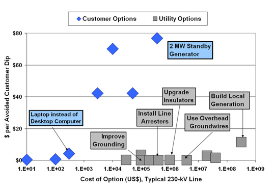
Applying TLSAs to reduce switching surge factors allows design of a more compact line with lower material costs, easier construction and narrower ROW. Table 3 summarizes cost comparison between three alternatives.

Design of Transmission Line Surge Arrester
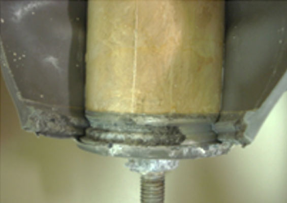
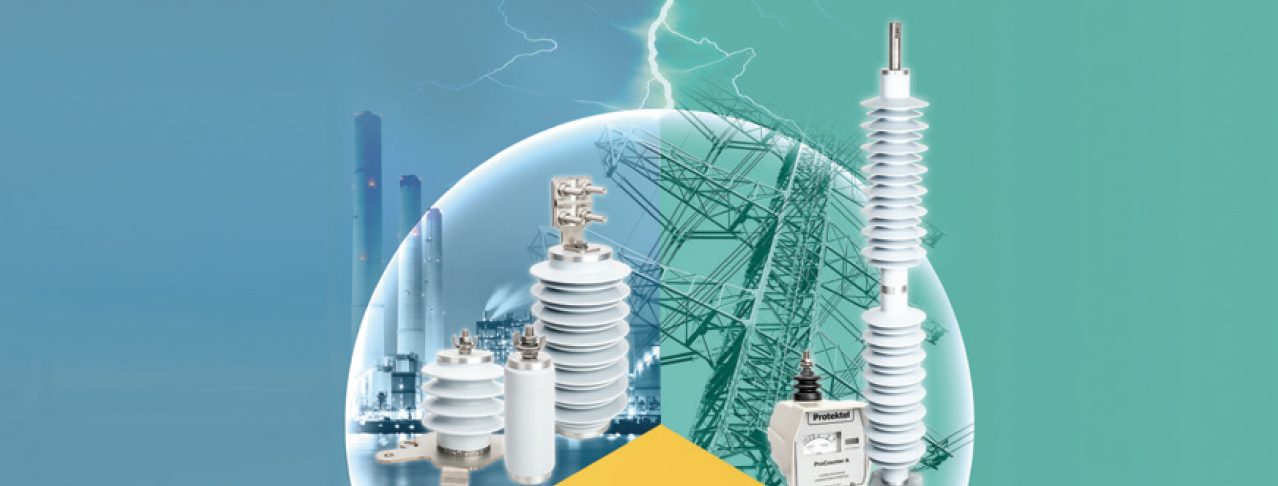
The structure of an arrester is simple for most standard applications and consists of a stack of cylindrical MOVs (non-linear resistors made of ceramic material), placed inside a housing. Modern metal-oxide varistors consist of approximately 90% zinc oxide, a semi-conductor, and about 10% additives that act as doping elements. Grain size of the raw materials is only about 1 µm, necessary to achieve high homogeneity when wet-mixing ingredients and important towards quality of the end product. The second important component is the housing that provides mechanical and dielectric strength, connection to the energy system and earth and protection against environmental stresses. Over the past decade, polymer-housed surge arresters have become more popular due to their compact design, lower weight, more efficient production and better performance.
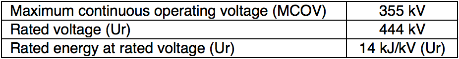
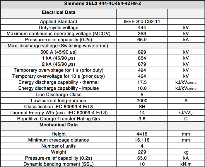
The most suitable design for line surge arrester application is the cage design, whereby the stack of MOVs is surrounded by FRP rods that form a stable cage. In this case the active part becomes part of the mechanical support system made possible by the compressive strength of the MOVs. During manufacture, a stretching force is applied to the FRP cage and the varistor stack is clamped between the metal end fittings. Resulting mechanical strength of the arrester is based on pre-stress applied during production. After the cage pre-manufacture, an HTV silicone rubber is molded directly onto the varistors, the FRP rods and the end fittings. Modern cage design arresters reach high mechanical strengths and can be used up to 550 kV (station class) and therefore for all line surge arrester applications. Table 4 lists technical ratings for the non-gapped line arrester (NGLA) selected for the MMTP.

Conclusions
Switching surge overvoltage on transmission lines can be effectively reduced utilizing TLSAs, which also help optimize tower design and right-of-way width. In the case of the 500 kV MMTP, TLSAs allowed reducing the switching surge factor from 3.5 p.u. to 2.5 p.u. when combined with other design enhancements identified for the series capacitor. A lower switching surge factor also helps transmission line designers optimize tower design to make it more compact and reduce required land. Significant cost savings are achieved in comparison with other options.
Bibliography
[1] EPRI, “Outline of Guide for Application of Transmission Line Surge Arresters—42 to 765 kV” Project ID 1012313
[2] CIGRE Technical Brochure 440, “Use of Surge Arresters for Lightning Protection of Transmission Lines” Working Group C4.301
[3] CSA standard C22.3 No. 1-15 “Overhead Lines”
[4] CIGRE Technical Brochure 348, “Tower Top Geometry and Mid Span Clearances” Working Group B2.06
[5] EPRI, “500-kV Transmission Line Design” Project ID 1022363
[6] P. Bunov; L. Klingbeil; M. Schubert; B. Gossler; D. Biswas; James Hunt; R. Thallam; A. J. F. Keri, “Transmission line arresters application for control of switching overvoltages on 500-kV transmission line” 2014 IEEE PES T&D Conference and Exposition