Before installation on overhead lines, the quality of polymeric insulators must be approved through full design and type testing. Subsequently, manufacturers are responsible for performing sample and routine tests. These days, many users also demand special acceptance tests.
This edited 2019 contribution to INMR by EGU HV Laboratory in the Czech Republic looked at key lessons based on 25 years of design and type testing these insulators. For example, long-term testing has shown that failures of polymeric insulators occur mostly during interface testing. Indeed, while the current IEC 62217 standard dealing with polymeric insulators specifies tests on interfaces to verify quality, experience has shown that composite insulators with poor housing adhesion sometimes pass. For that reason, IEC 62217 has been under revision with the goal of stricter criteria to improve detection of defective insulators through interface testing.
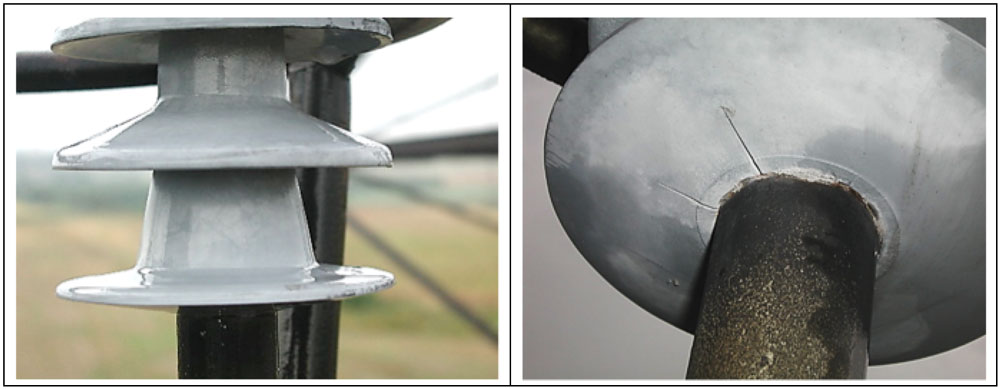
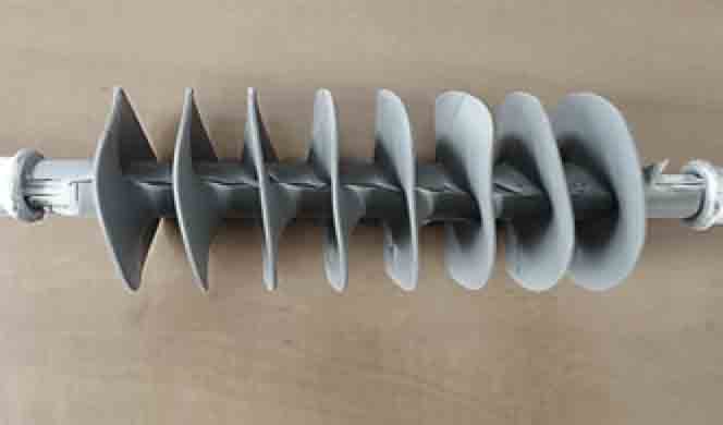
In 1995, polymeric long-rod insulators from 6 manufacturers were installed on the same 110 kV line in the Czech Republic. Fig. 1 shows the appearance of one of these insulators, with a silicone rubber housing, as revealed during inspections conducted in 2000 and 2006. All insulators evaluated during these inspections were in good to excellent condition with respect to electrical and mechanical properties, although some color change, chalking, minor surface cracking and decrease in hydrophobicity were recorded.
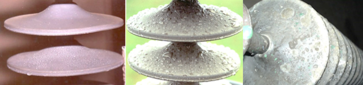
A long-rod polymeric insulator with EPDM rubber housing was installed on one tower of a 400 kV line in early 1990. Fig. 2 shows results of visual examination of this unit in 2002. Chalking of the housing was noted and all insulator samples had become fully hydrophilic. While there was no evidence of tracking or erosion, the lower part of a bottom shed showed cracks, most probably due to exposure to corona. An improper design of corona ring design was later identified.
Polymeric Insulator Failures in Czech Republic
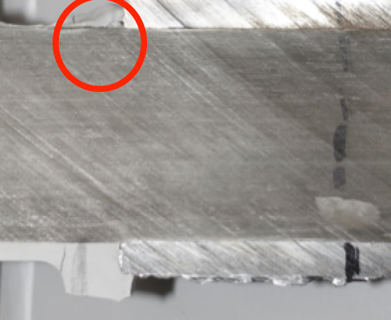
Since the start of application of polymeric insulators by Czech TSO, CEPs, there have been two notable incidents of brittle fracture failure. In one case, a polymeric tension long-rod installed on a 220 kV line failed mechanically 6 years after being installed in 2000. Fig. 3 shows an example of such a typical brittle fracture subsequently observed during laboratory testing.
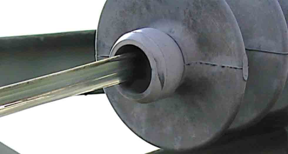
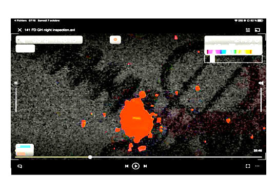
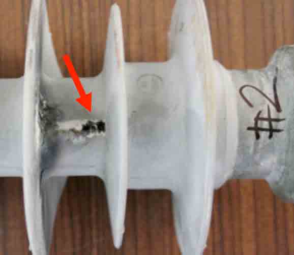
Moreover, an insulator installed on a 400 kV line in a double tension set failed in 2017 (see Fig. 4), 10 years after being put into service. A power arc occurred due to internal flashover and affected two-thirds of one insulator within the set. In this case, improper bonding between insulator housing and the core rod was detected (see Fig. 4). Failure root cause was investigated and determined to be moisture ingress and propagation along the faulty housing-rod interface.
Experience from Independent Testing
A large number of different polymeric insulator types and construction have been tested at EGU HV Laboratory according to relevant international standards. It is important to note that the tests given in these standards represent minimum technical requirements to ensure expected service performance. It is also important to emphasize that insulators fail during testing and some fail during service as well.

Evaluating Test Results
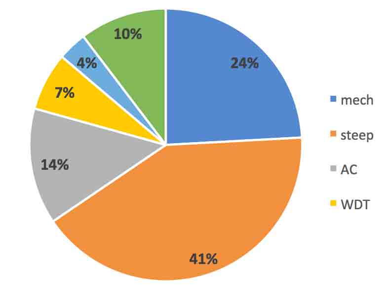
Based on long-term evaluations conducted at this test laboratory, about 10% of all polymeric insulators subjected to design or type testing fail. Fig. 5 categorizes these insulators per type of test where failure occurred. From these statistics, it is clear that insulators fail mainly during interface tests by means of steep-front impulse testing (41%) or by successive dry AC withstand testing (14%). In other words, some 55% of all types of insulator failures occurring under laboratory conditions are related to interface testing.
Mechanical Testing
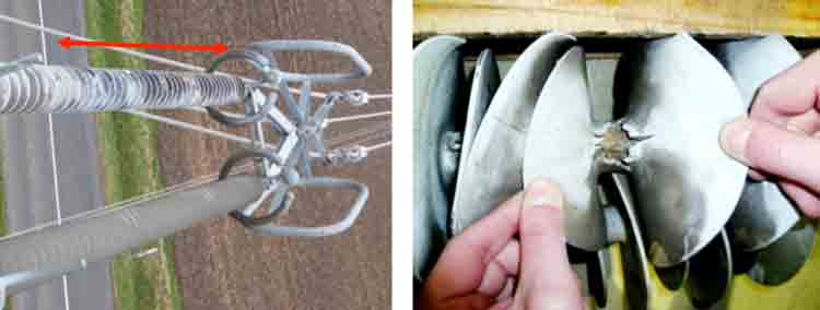
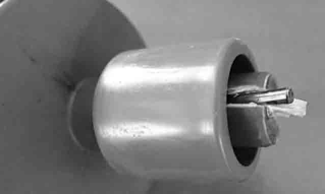
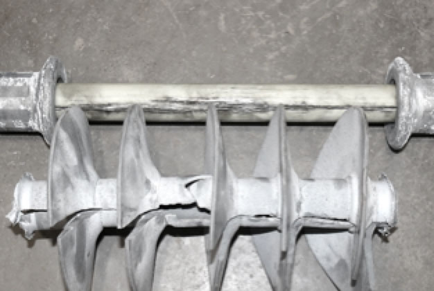
Mechanical performance of insulators is critical since catastrophic mechanical failure could lead to a line drop, widely considered the most severe situation that can be encountered during service. Mechanical properties of polymeric insulators are verified through testing as defined in relevant international standards. Moreover, experienced manufacturers have also implemented various methods and techniques to ensure high quality attachment of end fittings to the fiberglass core, i.e. avoiding issues related to under-crimping or over-crimping (see Fig. 6). Proper choice of end fitting materials with regard to the crimping technology and procedure used is also critical, as are design aspects such as rod parameters, etc. Although most manufacturers have learned these factors either from their own experience or from publically available technical sources, unusual problems are still encountered, as shown in Fig. 7, where failed end fittings had been attached by means of a pin going directly through the core.
Electrical Testing
Insulators in service must withstand not only normal operating voltage but deal with temporary overvoltages as well. For this reason, standard electrical tests such as power-frequency or impulse tests are carried out as a part of type testing. Moreover, steep-front impulse testing is available not only as a part of interface testing but also as a dielectric test simulating stresses due to fast transients. For example, steep-front impulse testing of the sample in Fig. 8 failed in the area with integrated grading ring due to a weak point in the interface between silicone housing and end fitting. Fig. 9 shows a sample that failed at the critical triple point interface of housing, rod and end fitting. In this case, steep-front impulse testing detected a localized defect in the fiberglass rod.
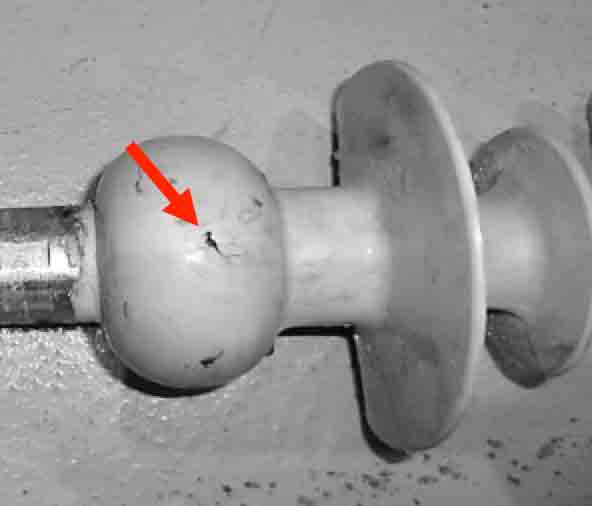
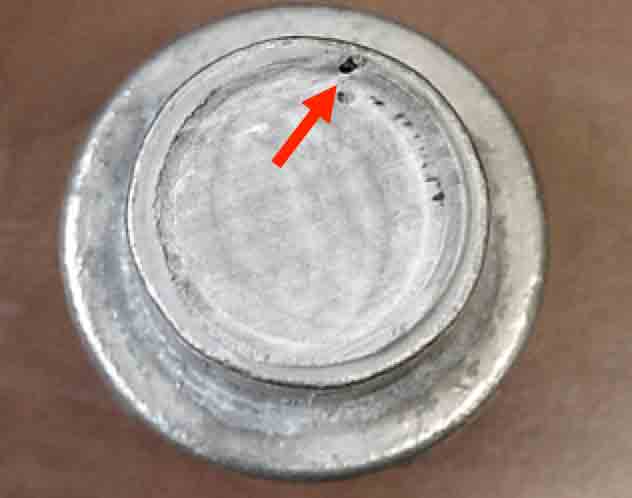
Fig. 10 illustrates a typical puncture at the triple point due to poor insulator design. Many polymeric insulators are designed these days with a large overmould of housing to allow for longer creepage distance for a given section length. But in such cases the higher electrical stress in the area of the triple point must be taken into account and adequate housing thickness must be calculated for that area to avoid puncture, not only during steep-front impulse testing but during service conditions as well. Fig. 11 shows poor end fitting construction that created a sharp edge that caused high electrical stress at that point. The result was electrical puncture.
There have been proposals to exclude steep-front impulse testing from the interface test sequence. However, based on such experience, the steep-front impulse testing should be maintained in a revised IEC 62217. It not only represents an important component of interface testing but is also a robust dielectric test to evaluate dielectric properties and construction of the materials used in composite insulators.

Interface Testing
Interface testing is a complex test relating interfacial properties to quality of composite insulators. Indeed, according to experience at EGU HV Laboratory, the most common reason for failure of polymeric insulators during a design test would be a failed interface test. Yet the present test sequence and criteria given in IEC 62217, as it now exists, still allows some test samples with poor housing to rod adhesion or to end fittings to pass. Fig. 12 shows a sample with no housing adhesion to the core and which failed during steep-front impulse testing. However, the sample shown in Fig. 13, also found to have poor or inferior adhesion, passed interface testing.
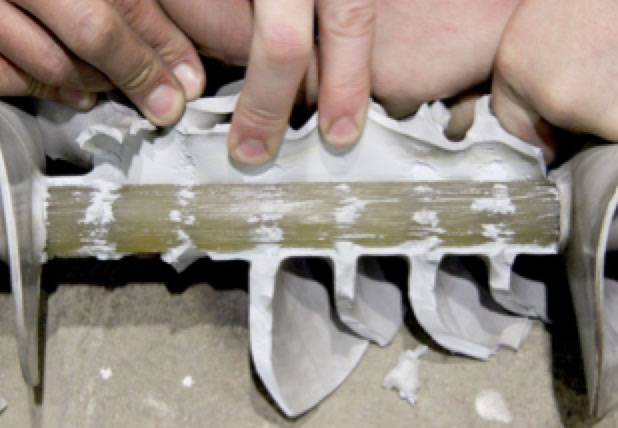
An investigation was therefore conducted involving an insulator with very poor bonding to the core rod as well as on one with good bonding. Three voids through the housing shank and reaching the core rod with an area of 1 cm2 were uniformly distributed along the length of the insulator sample with poor bonding. A modified interface test was then conducted for both, consisting of boiling the samples for 42 hours and performing the power-frequency withstand test for 30 min. An infrared camera was used to monitor temperature of samples during the test. Figs. 14 and 15 show the temperature distribution of the two samples.
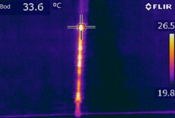
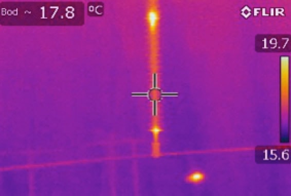
The sample with the bad housing bond showed a temperature rise of up to 19°C during the power-frequency withstand test. Water penetrated through voids and distributed along the rod to housing interface due to lack of bonding and resulted in resistive current flow that created heat. On the other hand, the sample with good interfaces showed a temperature rise of only 1.3°C. According to the present IEC 62217, a temperature rise in the housing shank of up to 10 K is acceptable during the power-frequency withstand test. But, based on testing experience, that value is too high since resistive current flow would create such heat. Sound insulators with no bonding issues would still show a temperature rise of up to 2°C. Moreover, uncertainty in temperature measurement and other testing conditions would also have to be taken into account.

Water Diffusion Test
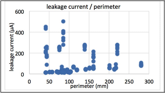
The water diffusion test (WDT) represents another element in design testing of polymeric insulators and involves testing the core rod with focus on its resistance to hydrolysis. If considering samples cut from fully finished insulators, the WDT can also serve as a useful housing to core interface test, i.e. checking the quality of housing bonding. A large number of water diffusion tests have been performed on different insulator type samples with and without housings but mostly involving samples cut from finished insulators. Data from voltage tests were collected as a part of these WDTs. For example, samples of from 13 mm to 89 mm diameter were tested with two electrode pairs of different diameters. Since electrode diameter does not play a significant role in given rod diameter range, test results could be grouped. Fig. 16 shows measured leakage current per perimeter (i.e. π x d). Clearly, test results involve low as well as high leakage currents for the same or similar perimeter values.
Firstly, results should be separated to differentiate between resistive and capacitive leakage currents given that capacitive leakage current depends on surface area of test sample. As such, test samples with larger surface area would show higher capacitive leakage currents. Leakage current density was then calculated per sample surface, as shown in Fig. 17 (current density in a logarithmic scale).
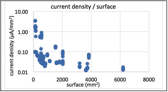
Purely capacitive leakage currents would have current densities below 0.1 µA/mm2 whereas higher leakage currents with resistive components would show current density values above 0.5 µA/mm2. Values above 0.5 µA/mm2 were therefore removed from test results to better define relationship between sample perimeter and leakage current value when it is purely capacitive. In other words, if test samples are dielectrically sound, only purely capacitive leakage currents are being measured.

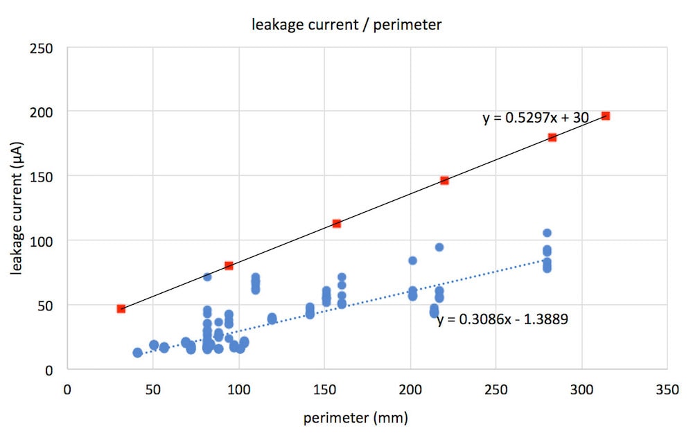
Subsequently, step leakage currents with resistive parts were taken out so that only capacitive leakage currents are shown and a linear equation was introduced representing an approximation curve. A standard deviation was then from calculated current densities, a three-sigma coverage factor was chosen and a linear approximation function was calculated. Finally, the approximation curve was moved to represent an upper envelope (see Fig. 18). That curve would represent maximum acceptable leakage current per given test sample perimeter/diameter.
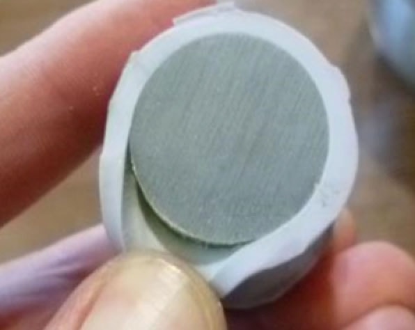
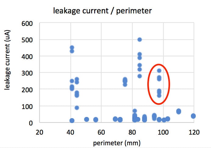
Acceptance criteria given in the existing edition of IEC 62217 specify that leakage current for any sample diameter during the voltage test not exceed a maximum of 1 mA. But as demonstrated above, that value is too high and is now also under revision by IEC TC 36 / MT 19. There are still cases where the WDT cannot reveal samples with poor or even no bonding (see Fig. 19). Leakage currents measured during the voltage test with diameter of 31 mm are summarized in Fig. 20 and marked with a red oval. Some samples of given diameter with poor to no bonding might show low leakage currents of 0.15 mA – 0.3 mA. Maximum acceptable leakage current for samples with perimeters of 100 mm and less should be well below 0.1 mA, as shown in Fig. 18.
Conclusions
Polymeric insulators have been used on the Czech transmission grid for more than 25 years and service experience has been positive. Nonetheless, there have been two reported cases of failures on 400 kV lines. Other problems in regard to polymeric long-rod insulators have related to unexpected line outages caused by bird streamers and the shorter dielectric (dry arc) distances being used. Such issues can be resolved by measures such as installation of effective bird discouragement devices.
Based on long-term experience testing polymeric insulators, about 10% of such insulators subjected to design and type tests fail and up to about 55% of such insulator failures are observed during interface testing. One major problem detected in certain polymeric insulators has been interface quality, i.e. quality of the housing to core or housing to end fitting bond. Such experience and results with interface and water diffusion testing have been delivered to IEC TC 36/MT 19, charged with revising IEC 62217.
References
[1] IEC 62217:2012 Polymeric HV insulators for indoor and outdoor use – General definitions, test methods and acceptance criteria.
[2] Sklenička, V.: “Transmission line insulators failures analysis in the Czech Republic – Annual review for ČEPS a.s.” (in Czech), Prague, January 2018.
[3] Sklenička, V.: “Evaluation of composite insulators used in transmission lines operated by ČEPS a.s. (in Czech)”, Prague, November 2013.
[4] Lachman J.: “Electrical failure analysis of a polymeric insulator installed in a 4OO kV transmission line operate by ČEPS a.s. (in Czech)”, Prague, June 2017.
[5] Lachman J. and all.: “Research into an increased number of unexplained line outages of polymeric insulator sets used within the Czech transmission grid”, paper B2-208, Cigre General Session 2016, Paris.