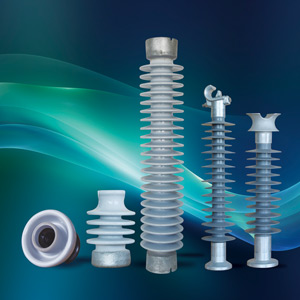
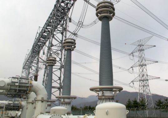
Replacement or retrofit of medium voltage (MV) bushings is common practice after decades operating a power transformer. At the same time, leaks or cracks detected in the porcelain cause operators to conduct maintenance to resolve these issues when other transformer services are also necessary. In such cases, only parts of the bushing have typically been replaced, such as the gaskets or the housing. Now, with increasing knowledge of other options, a trend has started to replace the porcelain bushing with composite polymeric types which can deliver benefits in life extension, reduced maintenance cost and enhanced protection of an ageing transformer fleet.
This edited two-part contribution to INMR by Dave Fishman and Ricardo Arrigoni of Maschinenfabrik Reinhausen in Germany reviews the justification of this process as well as the main considerations in bushing selection. It also discusses the main reasons for replacement, the advantages for composite polymeric bushings as well as improvements in their standards.
Medium voltage (MV) bushings, whether solid or oil-filled, are defined in the transformer world using different commercial and technical nomenclatures. IEC defines that MV bushings are up to 52 kV nominal voltage and can be either a porcelain or a composite polymeric type.
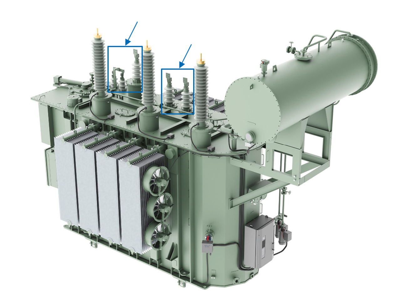
Reasons for Replacing MV Bushings
The main reasons for retrofits of MV transformer bushings can be divided into different categories. all transformer operators have probably faced one of these problems:
Leakage
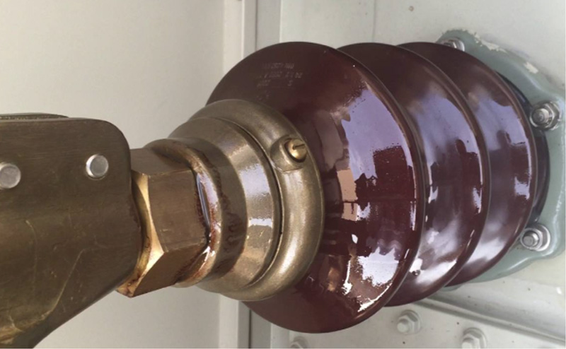
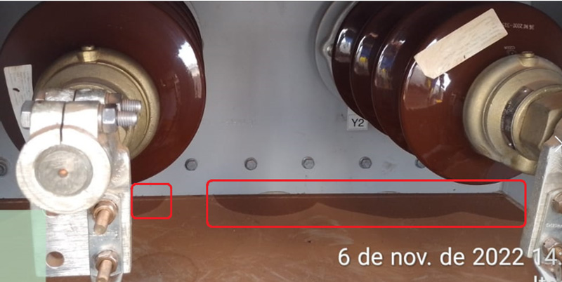
MV porcelain bushing standards, such as DIN, were published in the 1950s. In spite of their robust design and extensive service experience, it has been hard to avoid some cases of leakage in the field after years of operation under different environmental conditions. For example, it is relatively common to find some transformers with bushing oil leakage on the flange (i.e. in the sealing between tank and bushing) or at top part (i.e. in the sealing of the porcelain with metal parts).
The reasons for oil leakage are varied and include quality or selection of gasket materials, the porcelain housing being out of tolerance, improper assembly torque or assembly, centralization of the copper bolt and gaskets, finishing of sealing surfaces, loading on internal and external leads and extremely low or high temperatures.
These days, even small leakages are regarded as critical due to focus on the environment and possible penalties that could be applied. Indeed, soil contamination from leaked transformer oil is one of the main concerns facing grid operators and one of the most requested field services is dealing with leakage on transformer sealings.
Vandalism
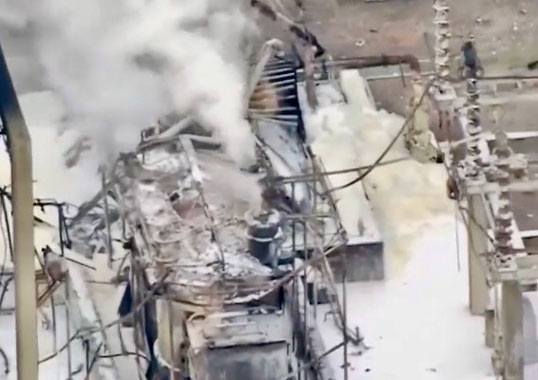
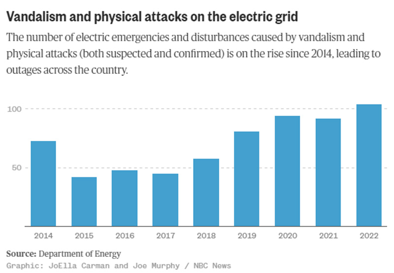
Power transformers are essential for the reliable operation of transmission and distribution grids and have been designed over decades to withstand short-circuit, lightning, severe weather and earthquake. Most power transformers are installed outdoors in urban areas and exposed to harsh conditions as well as being vulnerable to impact by humans. Substations are now mostly unmanned and digitalization is moving in the direction of central control of the grid. Intervention for maintenance is done only in cases of failure or routine scheduled maintenance. Substations are equipped with numerous fragile components and vandalism (and even terrorism) are problems that every utility must deal with. Porcelain insulators are especially susceptible to vandalism from objects launched at them or from gunshot. Any resulting damage can cause serious problems for substation equipment, from oil leakage to explosion.
To increase their robustness against such risks, there has been clear movement by utilities toward specifying composite housed bushings such as resin-impregnated synthetics (RIS) and resin-impregnated paper (RIP) types for the high voltage side. Should silicone composite bushings be penetrated by a bullet or hit by sharp objects, this will not lead to fire or damage, as can sometimes be the case with porcelain.
Cracks in Porcelain
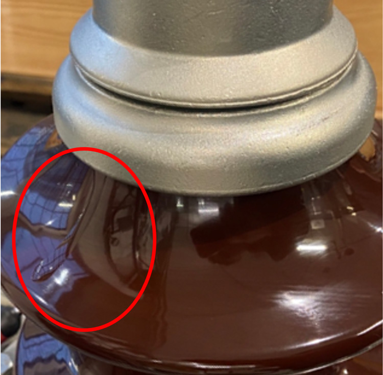
Being a fragile, heavy and brittle material, great care must be taken during movement or handling of porcelain. For example, during transformer cleaning, re-painting or other maintenance, porcelain bushings could be struck by tools, cranes, stairs and other objects that could cause cracks on the sheds. In the best case, oil leakage will not occur and the sheds could be temporarily repaired until replacement.
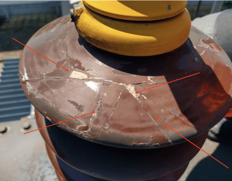
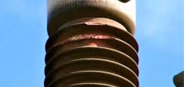
In event of damage, it is recommended to replace the entire bushing (or only the porcelain and gaskets under certain conditions). Replacing a bushing requires reducing the oil level in the transformer until a certain level. Due to this complex operation, being conducted in the field, transformer operators try as much as possible to avoid replacing bushings if not severely damaged and instead use different type of glue and materials to repair the sheds (see Fig. 5). Composite silicone bushings are designed to be more resistant, lighter and more flexible, making it safer for technical staff who must work surrounded by fragile devices on the transformer cover.
Fragmentation of Porcelain
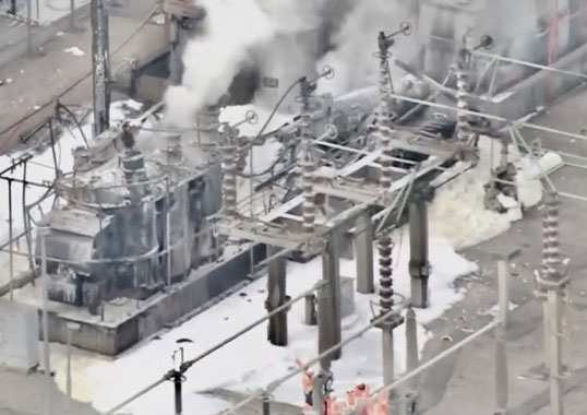
The main risk of porcelain insulators is from fragmentation. In event of catastrophic failure, sharp fragments can be launched many meters and damage other equipment and even present a safety hazard for personnel. To avoid such risks, some utilities establish exclusion zones up to 40 or 50 m in radius.

Refurbishment & Modernization
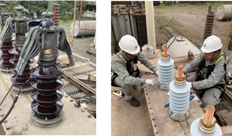
There has been a clear move toward silicone composite bushings in technical specifications for new transformers whenever electricity supply modernize their transformer fleets. Users are increasingly recognizing the advantages of composite polymeric bushings and replacing old porcelain bushings with new composite polymeric types during planned maintenance. At the same time, utilities are gaining experience with silicone insulation material and it has become common to modernize old transformers with new bushings, while also applying existing technical specification to the new transformers. The advantages to utilities of having standard, modern bushings can be significant due to reduced need for stock, consistent technology being applied, same maintenance programs and reduced risk of failure.
Creepage distance against pollution has also been increased by transformer operators over the years. With the same footprint, a composite polymeric bushing can offer higher creepage versus porcelain, in some case even doubling this parameter.
Issues Replacing Porcelain with ‘Like for Like’ Material
The options available when replacing older MV porcelain bushings have typically been limited. In the simplest case, the style of porcelain can be linked to a specific international standard and replacement is then ‘like for like’. However, due to the age profile of equipment now in service, the ability to identify a specific type of porcelain and dimensionally confirm its interchangeability can be a challenge. There are standards such as DIN 42533 that fully define the porcelain as well as all associated components and allow some confidence in offering ‘like for like’ replacement. But outside of such fully defined standards, there can be an array of individual country standards and different bushing manufacturers that do not allow complete interchangeability with today’s porcelain.
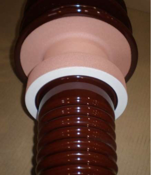
In the past, when replacing a porcelain bushing with a ‘like for like’ solution was required, it has been necessary to ‘reverse engineer’ a solution using a low volume, customized replacement. But the decrease in number of porcelain manufacturers and subsequent loss of flexible supply has resulted in such low volume porcelain supply being costly and also having a long lead time. At times, this option may not even be available for specific customer requirements. Fig. 9, for example, shows a recently exchanged NER bushing that was reverse engineered and supplied to the customer in a time frame of 16-weeks.
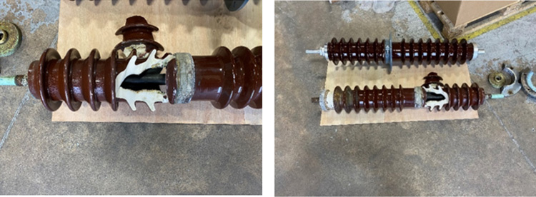
When reverse engineering a porcelain to achieve a ‘like for like’ solution, one still has to consider unknowns that may not be picked up by simply copying components and bringing them together in an assembly. These risks include increased cantilever load, different porcelain tolerances that impact assembly and installation, etc.
Today, a growing number of network operators are making the transition to composite type bushings for all new installations. This raises the question whether a replacement bushing can also be supplied as a composite solution instead of the simply replacing the original porcelain. Indeed, when replacing older HV bushings there has been a notable trend by network operators away from porcelain and toward composite types. A MV composite bushing solution can be adopted in a similar manner. Moreover, in addition to their performance advantages, composite insulators can be adjusted to offer a wide variety of interchangeability, making replacing porcelain a simpler option.
When selecting a dimensionally similar composite bushing to replace a porcelain bushing, the new solution is typically electrically superior within a smaller envelope. As such, a number of key concerns can be addressed simply by starting with an improved basic insulator. For example, the flexibility of a composite insulator compared to a traditional porcelain solution is highlighted by the flange mounting arrangement. This can easily be modified to offer bushing mounting interchangeability with top and bottom connection points being extended to offer identical arrangements on both the air and oil sides.
Bushing Replacement Selection Process
Information regarding an existing bushing to be replaced can be obtained from the rating plate of the transformer, the rating plate of the bushing (depending on type), the markings on the porcelain and, ideally, a general drawing of the bushing from the transformer’s O&M manual. However, it is not unusual for only limited technical information to be available for a bushing being replaced. In fact, in extreme cases, when only the transformer name plate is available, bushings need to be removed for dimensional inspection (see Fig. 10).
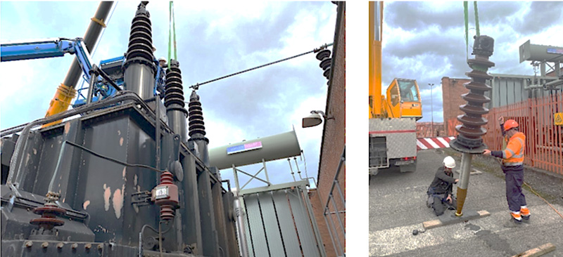
When considering the replacement of MV porcelain bushings for composite items the following points should be part of the basic considerations:
• Electrical Performance
· Rated highest voltage for equipment (Um)
· Rated current (Ir)
· Insulation levels (rated lightning impulse withstand voltage BIL and power frequency withstand voltage).
· Overload performance
· All other electrical characteristics to be as per IEC60137
• Mechanical Interchangeability
· Mounting hole size and plate thickness
· Flange fixing method – typically bolted flange with stud PCD.
· Flange sealing method (flat gasket or O-ring)
· Top connection terminal size
· Top connection position from mounting flange
· Transformer connection – solid conductor or draw lead
–Oil side solid conductor terminal size
–Oil side solid connector position from mounting flange
–Draw lead cable size
–Isolating tube internal diameter for draw lead O/D.
· CT accommodation with earth zone on bushing
· CT accommodation on extended bushing conductor
· Cantilever load withstand requirements for bushing assembly.
One area for concern that must regularly be dealt with on draw lead bushings is the connection of the transformer draw lead to the bushing. In certain applications, there is a defined connection point for the draw lead and a threaded connection joint at the connection point, as illustrated in example below:
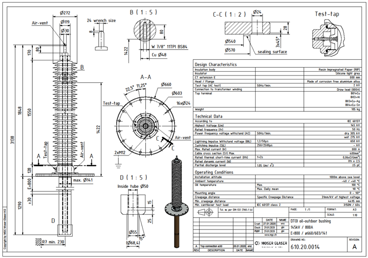
In this case, a simple solution can be provided that utilizes the existing draw lead connection point with the new bushing connection arrangement resulting in no modification needed to the draw lead of the transformer. Unfortunately, a defined connection point for the draw lead is not the norm so options have to considered for draw lead connection to an unknown bushing point. This can lead to a several options:
1. Unbraze the draw lead from the old bushings and re-braze onto the new bushing connection point. The concern here is of course based around the hot works on site typically on top of a transformer with a potential for exposed transformer active parts to this process – extreme care must be taken!
2. If the old bushing connection bolt thread size is known then a small intermediate connector can be used to modify the existing draw lead connector to the new bushing connection point. This possibility is reliant on having details of the existing bushing connection arrangement and the thread size may need to be checked by removal of the bushing as below typical example.
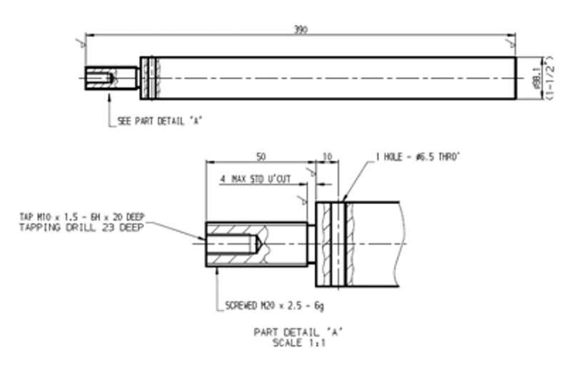
Additional considerations
Gasket sealing material
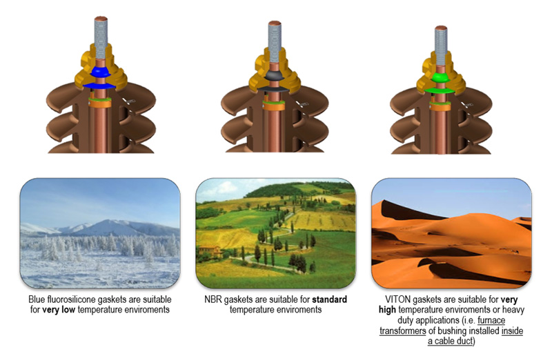
A variety of different gasket sealing options are available when supplying a replacement bushing assembly and these must be considered. For example, seal performance and selection of suitable sealing materials can have major impact on long-term performance. Therefore, attention must be given to the operating and climatic conditions of the bushing in order to ensure correct selection of gasket.
Corrosion of Metal Components
External metallic components of a bushing will be impacted by the environmental conditions of the installation. Any surface protection of these components must therefore be considered during bushing specification. As seen in Fig. 14, corrosion of metallic components can prove catastrophic if a bushing’s oil seal fails, resulting in moisture ingress and oil loss. Level of corrosion can also be impacted by the galvanic effect of dissimilar metals that have been in contact at the external point of the bushing connection.
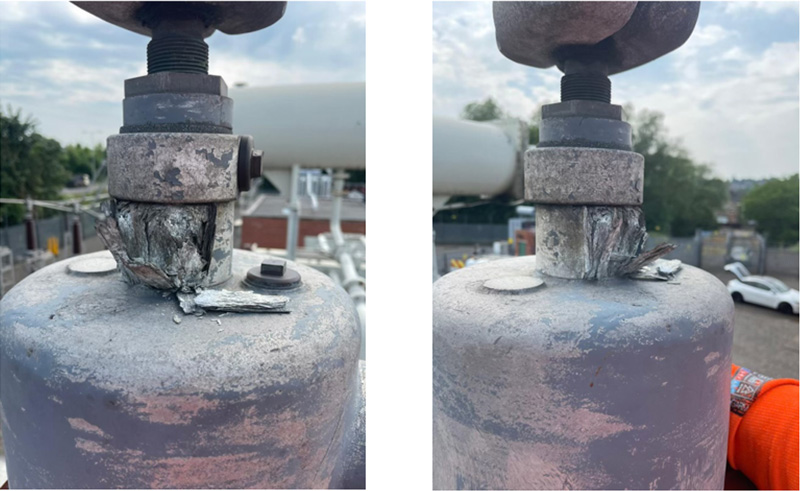
To address the potential for galvanic corrosion or to meet a bushing’s maximum temperature rise, it may be necessary to have a tin, silver or nickel plate at the terminals. The Table below shows the most common materials and surface treatments used on bushing terminals as well as the permitted respective combinations between materials so as to avoid risk of galvanic corrosion.

Simplification of Construction Comparing Composite Polymeric with Porcelain Bushings
New technologies and materials now provide the possibility of more modern, more reliable and simpler bushings. MV porcelain bushings, while used for decades, represent old technology with standards have been in place for more than 60 years. While some standards may have been updated or replaced, the basic concept remains the same. One example is replacement of DIN 42533 and DIN 42534 by EN 50180. The main difference with EN is the new style of porcelain, with different shapes of sheds and levels of pollution, thereby allowing more options for polluted environments without increasing voltage class.
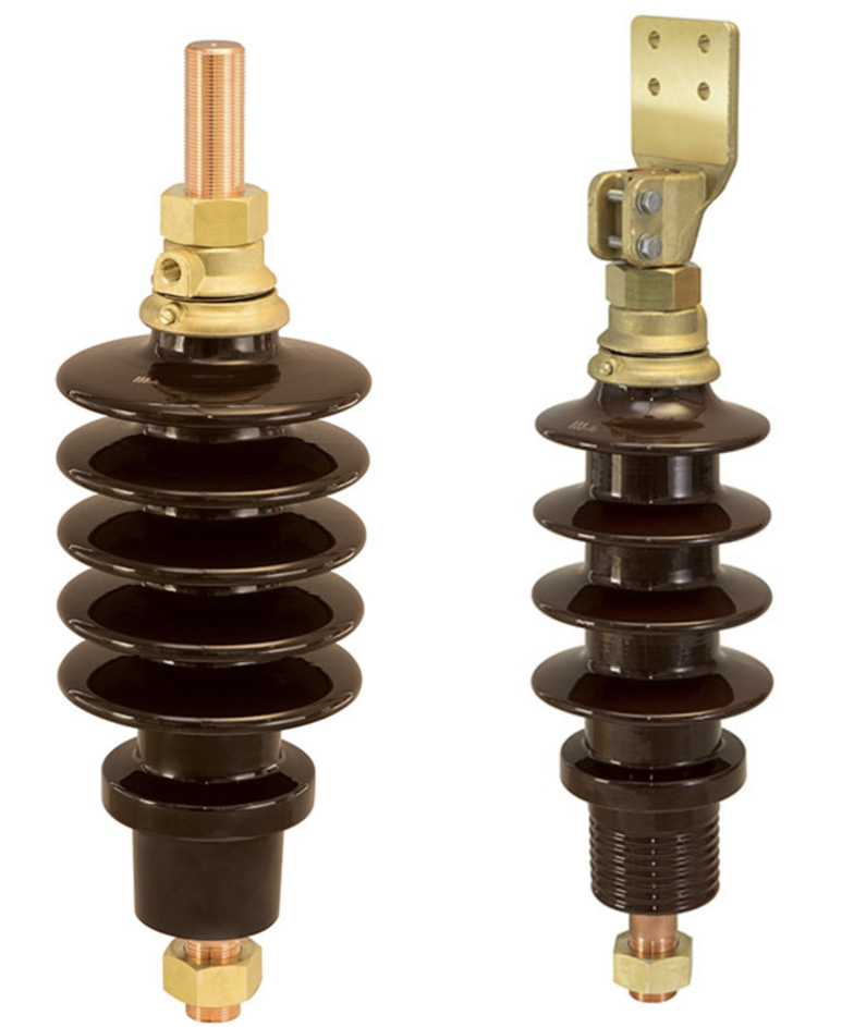
Since the mechanical part of the bushing remains the same as in the past, it is composite polymeric bushing technology that is driving any real change in MV bushings. Different solutions and types are already available and more under development to provide alternatives to porcelain bushings.
There are a number of important technical advantages when comparing composite and porcelain bushings:
Sealing System
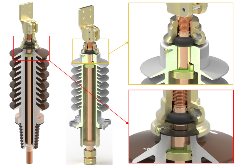
Composite polymeric bushing offer improved sealing and could be oil filled, dry-type or epoxy moulded. In the case of an oil-filled composite polymeric bushing from one supplier, for example, the flat gasket between porcelain and the upper cap has been removed and the same concept is applied as for HV insulators. Actually, the flat gasket at the top of the porcelain housing is one of the main areas vulnerable to leakage due to the sealing surface of the porcelain (planarity) and the upper cap which is made of brass. Thickness of the flat gasket is sometimes not sufficient to compensate for the tolerances between cap and porcelain and leaks can appear once the transformer is filled with oil.
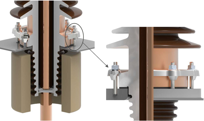
Fixation Flange of MV Porcelain Bushing
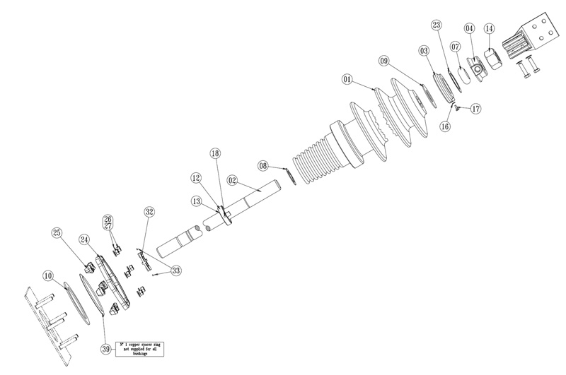
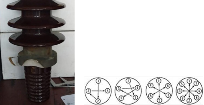
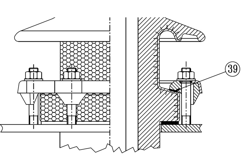
In the case of MV porcelain bushings, the flange and clamping blocks (kicker) are separated and must be mounted one by one. Separate small parts (i.e. not standard nuts or washer that could be easily replaced) are critical parts in the field and could be lost or just not despatched with the bushing. These fixing parts are not easy to assemble, considering working conditions and limited space.
Another difficulty for this type of fixing is that it must be carefully mounted and torque must be applied correctly using the concept of “X” (i.e. cross-pattern). Clamping risks breaking the porcelain if it is not properly mounted.
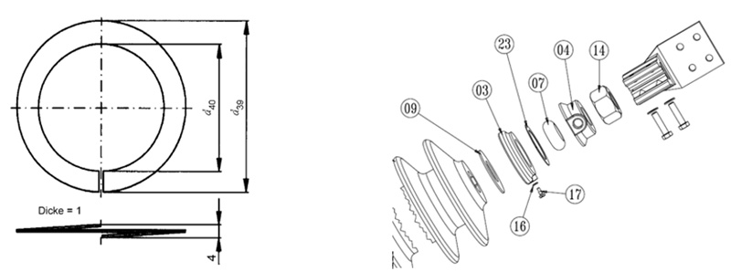
For a 52 kV bushing, metallization of the porcelain flange to achieve low levels of Partial discharges (PD) makes the porcelain even more fragile and easier to crack. A special ring plate (pos. 39 in the figure below) must be used to distribute the forces from the clamping blocks in the porcelain and to make sure that all blocks are grounded properly.
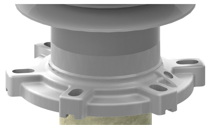
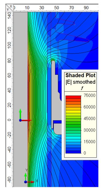
For composite polymeric bushings, the flange follows the condenser bushing style and is made in a single piece mounted or glued on the insulator. Besides the advantage of having no lose parts and no fragile porcelain, the flange gives robustness to the bushing and very low levels of PD. The design was made to homogenized the electrical field in the most stressful part of the bushing, the flange region. Still very important for PD is to vent the flange region properly during oil filling of transformer.
a. Creepage Distance
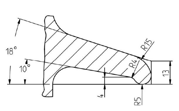
The shed profile of porcelain is defined by the material and its processing capabilities. Thicker sheds are necessary to have more material to form the sheds without becoming too fragile or suffering excess deformation during turning and finishing in the kiln. The moulding process of silicone, by contrast, allows for longer and thinner sheds, meaning increased creepage distances given the same insulator height. Fig. 25 compares the different profiles of porcelain and silicone sheds.
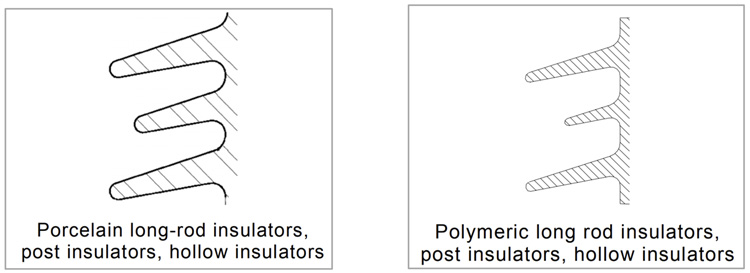
The manufacturing process for silicone insulators using injection moulding results in high quality as well as optimized shed shapes and dimensions. Shed profile, as specified in IEC 60815-1, allows for the possibility of higher creepages with the same footprint and height of MV bushings and means more safety for transformer operators without requiring an increase in overall transformer dimensions. This can be a perfect solution for retrofit applications, especially in polluted service areas.
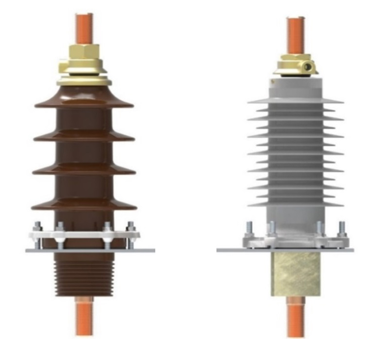
(creepage 680 mm versus 1180 mm for silicone).
b. Weight
MV composite polymeric bushings are at least 30% lighter than porcelain equivalents. Moreover, depending on voltage, the insulator could be 40 to 50% lighter than porcelain. During assembly of the transformer in the factory and especially in the field during service or retrofit, weight is an important consideration when handling bushings.
c. Mechanical Load Capabilities
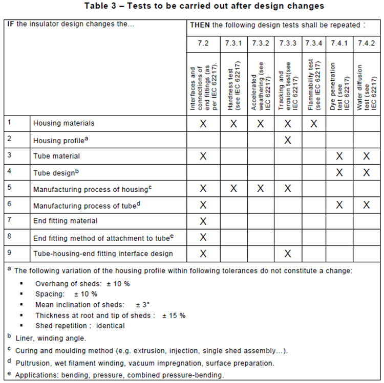
TMechanical load capabilities of composite polymeric insulators are higher than porcelain insulator. For porcelain bushings, for example, only the cantilever test according to IEC 60137 is required. For composite polymeric insulators, a bending load test of the insulator body according to IEC 61462 must be performed.

The additional tests below are mandatory for composite polymeric insulators and certifies the mechanical and electrical capabilities of the insulator body. Regarding composite polymeric insulators, it is not clear to all end users that tests below are mandatory in case of any change in the manufacturing, design or materials. These tests are very important to confirm that any change is not influencing the performance of the insulator.
Points of concern from DIN and EN porcelain bushing standards
As mentioned, the first edition of the DIN standard for bushings goes back to 1950 and has been updated over the years. This DIN standard has now been withdrawn and replaced by EN 50180 with valuable technical upgrades for transformer operators. Still, the DIN standard continues to be used due to its robustness and cost. In fact, some countries continue to follow this standard and have not yet updated to EN 50180.
DIN and EN standards define the porcelain, gaskets and metal parts in detail. From an end user perspective, this approach is perfect due to the high level of standardization as well as the possibility to easily source replacement parts from all over the world. On the other hand, this approach is restrictive and does not support development of new solutions by manufacturers.
Some points of concern regarding DIN and EN bushings, described below, could be used as the basis to upgrade bushing design and allow for new technical solutions that will result in superior MV bushings.
Sealing System
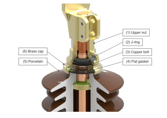
DIN and EN standards have used the same sealing system for decades. While a robust design, there are points that could be improved and upgraded. For the top sealing, the upper nut (1) compresses the J-ring (2), sealing the copper bolt (3). The force is transferred to the flat gasket (4) between the porcelain (5) and the lower brass cap (6). Such a system provides good sealing and an easy system for assembling the bushing.
For the top sealing, the upper nut (1) compresses the J-ring (2), sealing the copper bolt (3) and the force is transferred to the flat gasket (4) between the porcelain (5) and the lower brass cap (6). This system provides good sealing and an easy system for assembling the bushing.
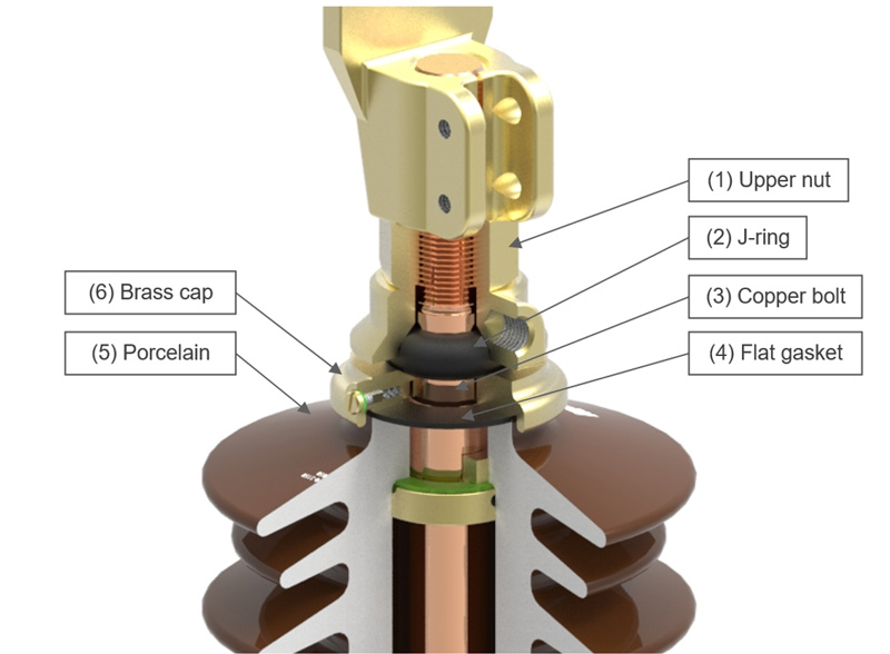
Concerns in regard to this type of sealing system relate to torque on the upper nut, planarity of the porcelain, centralization of the copper bolt and gaskets, porcelain tolerance, gasket material quality and correct transfer of torque applied to the nut so as to achieve the desired compression on the flat gasket. Basically, quality control of parts and correct assembly are both crucial for perfect sealing and skilled technicians are needed to carefully assemble bushings on site. Since no leakage test is performed outside the transformer, if any leak is detected, this will be during the transformer filling process or during the pressure test.
This means that it is necessary to have skilled technicians to careful assembly the bushings at site. No leakage test is performed outside the transformer, so, if any leakage detected, it will be during the transformer filling process or pressure test.
Flat Gasket Sealing Performance
The weakest point of sealing in a solid bushing is the top flat gasket. Unfortunately, many different factors could contribute to leakage. Given this, developments have been underway to find new types of sealing to replace the flat gasket. With testing, it has been possible to determine that the root cause of leakage is not only a single defect but rather a combination of factors.
A deep dive investigation with tests, analyses and FEM simulation were performed to find a system permitting more efficient sealing at the top of a bushing.
Porcelain Flatness Analysis
The first point checked was the flatness measurement of the porcelains. According to IEC 62155 Annex A, the parallelism of end faces is shown in Fig. 31. When turning the porcelain, the measurement of “P” should not be greater than 0.5 mm. The “P” defines only the parallelism of the surface and not the flatness of the top sealing surface of the porcelain. Yet this is important for the sealing system.
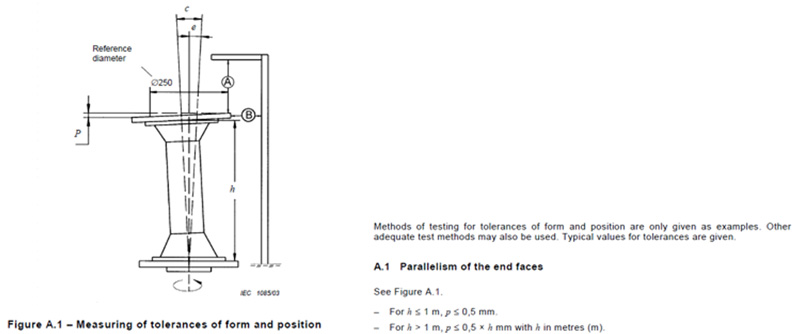
The EN standard specifies only the finishing surface according to Fig. 32. Planarity is extremely important due to flat gasket that will be used between the porcelain and the lower cap.

Compression Test of Flat Gasket
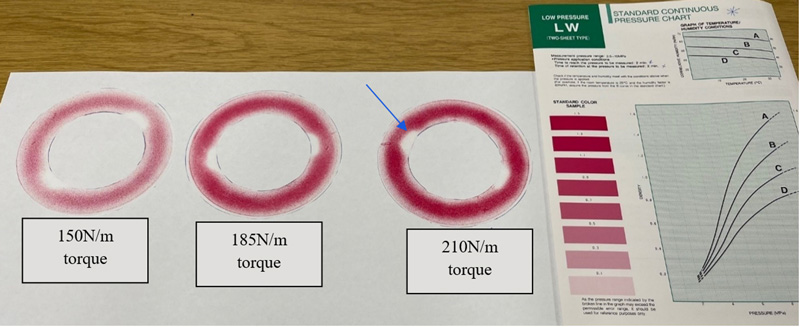
To analyse the compression of the flat gasket and the distribution of forces, a pressure sensitive film which changes colour based on the force applied over the area was used at the top of the gasket. This test showed behaviour of the flat gasket using different torques.

With the bushing in the vertical position and with perfect alignment of the copper bolt, metal parts and gaskets, 3 different torques were tested, as shown in Fig. 34. With the pressure film images, it was possible to determine the pressure applied on the flat gasket, distribution of forces and impact of the anti-rotating grooves of the porcelain. As shown by the blue arrow, the grooves in the porcelain to fix the copper rod considerably reduce sealing surfaces. This could impact in sealing performance.
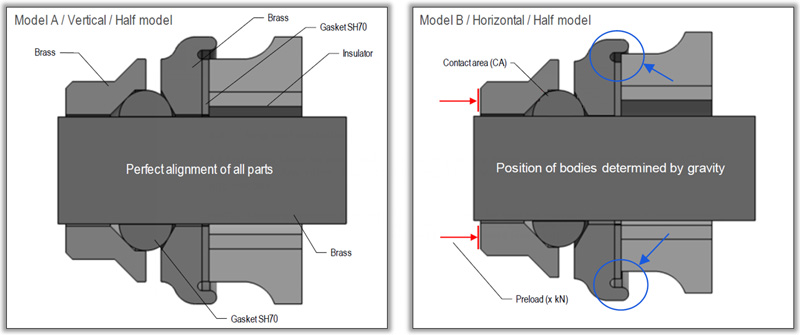
A second consideration involves a porcelain bushing assembled in the horizontal position. IEC 60137 item 4.6 states that bushings to be installed at an angle equal or greater than 70° shall be agreed between purchaser and supplier. This is not a clear statement that MV solid bushings could or could not be installed horizontally and creates challenges if leakage occurs. In this case, the specific bushing standard, such as EN 50180, should clearly define if the bushing is suitable for horizontal application. But there are no such references for installation.

Considering the tolerances between porcelain and metal parts, it was possible to determine the displacement of the copper rod in comparison to the porcelain. When the bushing is assembled horizontally, due to gravity, the copper rod and the anti-rotation ring will be supported by the porcelain and the copper rod and the flat gasket will not be completely in the centre line. This will reduce the sealing area at the top, as shown in Fig. 36.
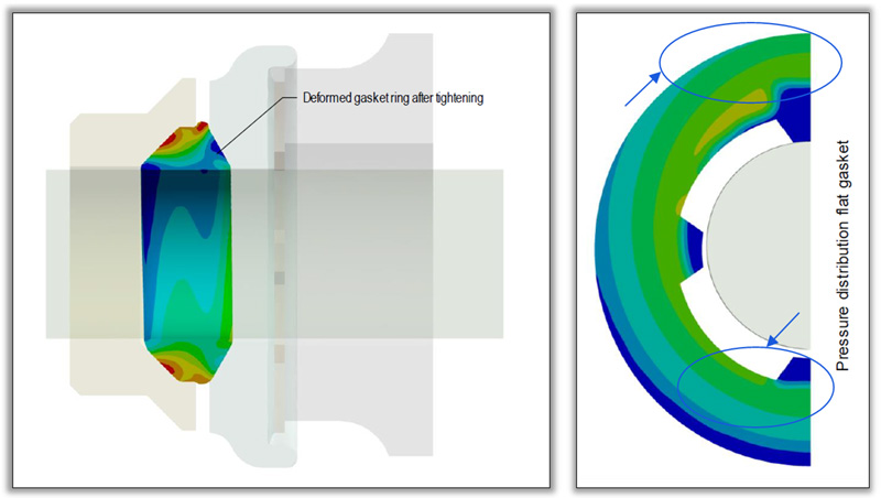
Using FEM simulation tools, it was possible to check that, in the event that the copper bolt and the gaskets are not perfectly assembled in the centre (due to weight of the copper bolt), distribution of forces over the flat gaskets completely changes. As shown in Fig. 37, the flat gasket’s force distribution is not in the centre of the sealing area and this could be a reason for leakage. It is therefore highly important to have perfect assembly of the copper conductor, metal parts and gaskets when a bushing is assembled. In the case of silicone composite bushings, this is not an issue because there is no flat gasket.
Equipotential Ring for Upper & Lower Cap
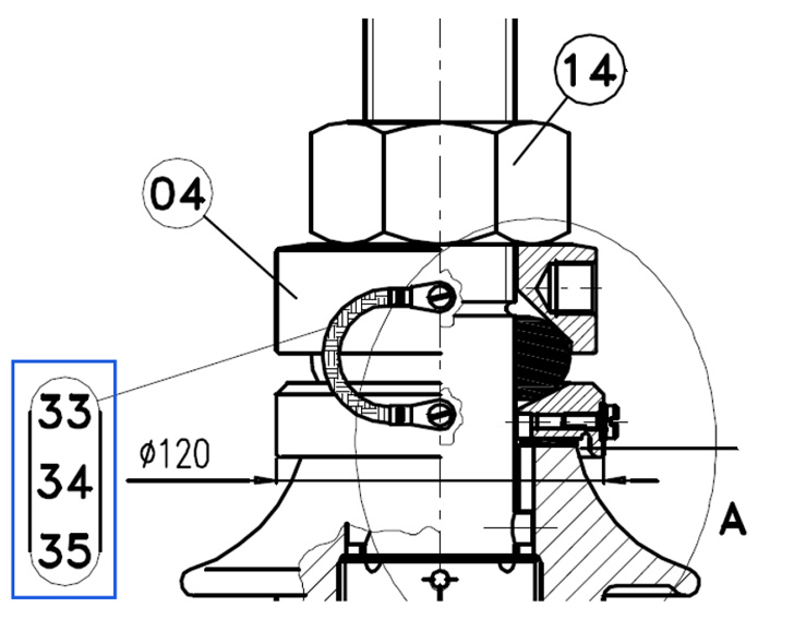
The equipotential ring for brass caps at the top part of a MV porcelain bushing is crucial for perfect operation. This equipotential ring, demonstrated in Fig. 38, is defined by the standard and is one more part of a MV bushing that must be assembled correctly. The risk of incorrect assembly of this part is high. For example, the bushing could be assembled without the ring and the problem detected only when the transformer is energized.
The nut used to fix the copper rod is in mechanical contact with the upper cap and both are at the same potential as the copper bar. The lower cap, without the equipotential ring, can fluctuate around the copper conductor. This could lead to partial discharges and temperature rise for high current bushings.
Simple solutions such as an external equipotential cable could solve this type of problem and, since it is visual, can give a signal to the technician if not assembled. In the worst case, the repair will be much easier and it will not be necessary to disassemble the external flag, nut and upper cap to include the equipotential ring.
Simple upgrades in MV bushing standards could bring more reliability for transformer operators while avoiding unexpected costs and failures in the field during service.
Conclusions
MV bushings are critical component in a transformer. They normally carry out high current values and should be part of any maintenance and inspection plan for transformer operators. Failure of a MV bushing could be compared to that of a HV bushing. A transformer could be severely damaged due to an explosion, fire or leakage.
With development of new technologies, upgrades in the standards are necessary and regulations for MV composite polymeric bushings should be in place.
Besides type tests for the complete bushing, as defined by local and international standards, bushing manufacturers must carry-out all type tests defined for composite polymeric insulators. The type tests mentioned in item 7.5 are especially crucial to verify the design and lifetime of composite bushings. A simple change in material or manufacturing process could cause busing failure. That is the reason why, in the definition, any changes require that type tests must be carried out again.
Special attention must be taken when specifying MV bushings. Type tests must be requested, even though porcelain bushings are a highly standardized product with their design proven over decades.
Given increasing experience with composite polymeric insulators installed at substations over decades, transformer operators are also gaining experience and recognizing the advantages of polymeric composite insulators compared to porcelain. At the same time, porcelain is becoming critical in the supply chain due to issues of price and delivery lead times. This could further accelerate the transition from porcelain to polymeric composite type MV bushings.
References
[1] DIN 42532-1; Indoor and Outdoor Transformer Bushings; Insulation Class 10 N to 30 N, 630 A, Assembly (withdrawn)
[2] DIN 42533-1; Indoor and Outdoor Transformer Bushings; Insulation classes 10 N to 30 N, 1000 to 3150A; Assembly (withdrawn)
[3] DIN 42534; Transformers; bushings for indoor and outdoor, series voltage 45 kV to 1000 A (withdrawn)
[4] EN50180-1; Bushings above 1 kV up to 52 kV and from 250 A to 3,15 kA for liquid filled transformers –
Part 1: General requirements for bushings;
[5] EN50180-2; Bushings above 1 kV up to 52 kV and from 250 A to 3,15 kA for liquid filled transformers –
Part 2: Requirement for bushing components;
[6] EN50180-3; Bushings above 1 kV up to 52 kV and from 250 A to 3,15 kA for liquid filled transformers –
Part 3: Requirements for bushing fixations;
[7] IEC 60137; Insulated bushings for alternating voltages above 1 000 V
[5] www.nbcnews.com
[6] IEC 60815; Selection and dimensioning of high-voltage insulators intended for use in polluted conditions –
Part 1: Definitions, information and general principles
[7] IEC61462; Composite hollow insulators – Pressurized and unpressurized insulators for use in electrical equipment with rated voltage greater than 1 000 V – Definitions, test methods, acceptance criteria and design recommendations
[8] IEC 62155; Hollow pressurized and unpressurized ceramic and glass insulators for use in electrical equipment with rated voltages greater than 1 000 V

