Normally, the concept of ageing of insulators is something associated mainly with composite or nonceramic types. However, this perception certainly does not suggest that other types of insulators do not also age.
This past INMR article, reported by Dr. Ravi Gorur, presented results of a test program involving porcelain insulators which had been in service for periods ranging from 10 to 70 years. The results of the research indicated that there is indeed irreversible deterioration occurring in porcelain insulators. In the case of some types of porcelain insulators which had not been in service for very long, the ageing experienced was significant enough to necessitate replacement as quickly as possible. The research also forcefully demonstrated that ageing can be highly variable among the various types of porcelain insulators currently used by the utility industry.

Introduction
Porcelain has served the electric power supply industry in an exemplary manner. Insulators made from this material have been used successfully since the very earliest days of power transmission and distribution, starting in the 19th century.
In spite of the obvious disadvantages such as being brittle (i.e. easily breakable) and dense (i.e. heavy) – both of which call for great care during handling – the inert nature of this inorganic material imparts tremendous stability in the face of the numerous environmental factors which can cause some organic materials to quickly deteriorate and fail.
There are many suppliers of porcelain insulators and, not surprisingly, there are also differences in the materials and manufacturing processes of the various products available. For distribution voltages, low strength quartz-based porcelain composition can work satisfactorily; for transmission voltages, by contrast, it is common to use high-strength, alumina-based porcelain.
Besides differences in the formulation of porcelain, there are also variations in the type of cement used for attaching the hardware. Although porcelain insulators have to satisfy certain uniform national and international standards, these are generally unable to establish the duration for which these insulators will remain useable.
Reduction of electrical and mechanical strength in porcelain has been studied widely in the past. Failures due to cement growth, propagation over time of cracks in the porcelain body, increased stresses around corners in the pin area and leading to puncture during lightning surges, improperly fired porcelain, etc. are all well-documented in the literature.
Most of these types of failure modes are not visible since they tend to occur inside the cap or pin assembly. Nevertheless, techniques for determining whether or not a porcelain insulator is electrically sound or not are fairly advanced and live-line maintenance (with bare hands) is a practice adopted by numerous utilities.
Porcelain insulators can be damaged while in storage, during installation or in service due to vandalism. In most cases, however, the number of broken units in the string is limited to one or two. Therefore, the insulator assembly should still be capable of supporting the line, both mechanically and electrically. However, if the damage to the affected discs is severe or, if a large number of units are broken, the electrical and mechanical strength of the string can be adversely affected.
Suspension insulators are generally subjected to average daily loads which represent only a fraction (circa 20 per cent) of their Mechanical and Electrical rating (M&E). Thus, there is a substantial safety margin when an insulator is new. This margin, however, will be reduced as the insulator ages during service.
Many utilities have ceramic insulators in their systems which now exceed the normally considered “acceptable life” of 30 years. These insulators may well continue to function for many years to come.
Nevertheless, it is logical that utilities would like to have information on when is the ideal time to replace them in order to plan maintenance strategies designed to minimize outages. It is also reasonable to expect that utilities are able to obtain samples of these insulators from their networks during maintenance cycles and which can then be examined and evaluated for this purpose.
One possible approach for evaluating the condition of these insulators would be to compare the mechanical strength of field exposed insulators after many years of service to their strength when new (or at time of purchase). Caution, however, has to be advised when using this approach as it is quite common for insulators to be stored outdoors for substantial periods of time before actual installation. There is thus the distinct possibility that these insulators, when installed, are already not as strong as in the new condition.
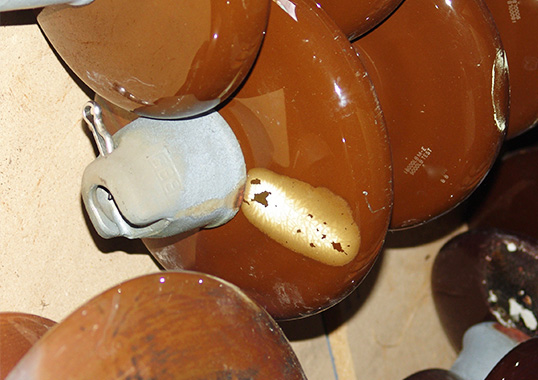
Regarding electrical properties, the surface and bulk aspects of the insulator body are important. Surface resistance could be reduced due to factors such as airborne contamination, erosion of glaze, surface roughening as well as accumulation of the by-products of hardware corrosion. Except for the first factor, which can be mitigated by natural cleaning, the rest of the sources of electrical degradation can lead to a permanent reduction in surface resistance. This will impact the performance of the insulator under contaminated conditions.

In the research reviewed in this article, both the electrical and mechanical aspects of samples of porcelain insulators removed from service (during regular maintenance) were analyzed. Most of the insulators removed had been in operation for a period of between 10 and 20 years; but some had been in service for more than for 50 years.
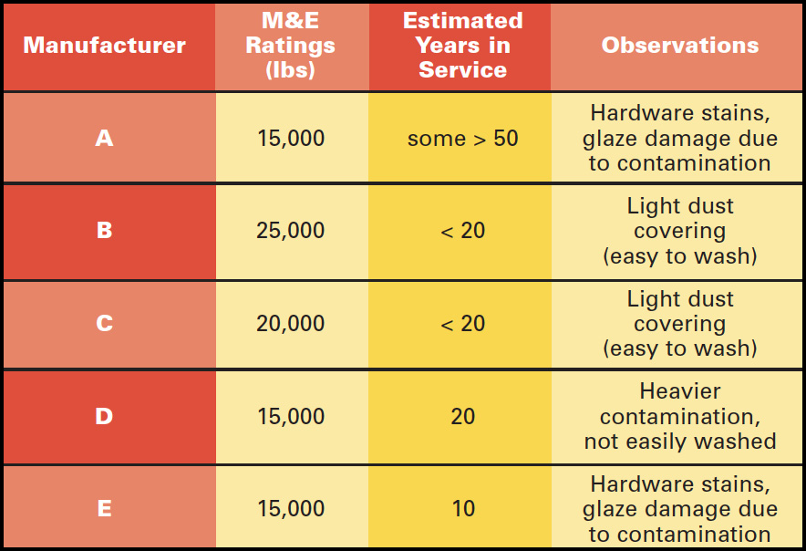
The porcelain bells were all removed from 66 kV and 115 kV systems in eastern Arizona in an area home to a number of copper mines. Table 1 summarizes the relevant information on this sample group of insulators. The insulators were from three different manufacturers and had M&E ratings of 15,000, 20,000 and 25,000 lbs.
CLICK TO ENLARGE
Electrical Tests
A. Surface Resistance Measurements
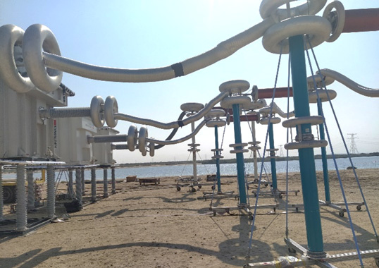
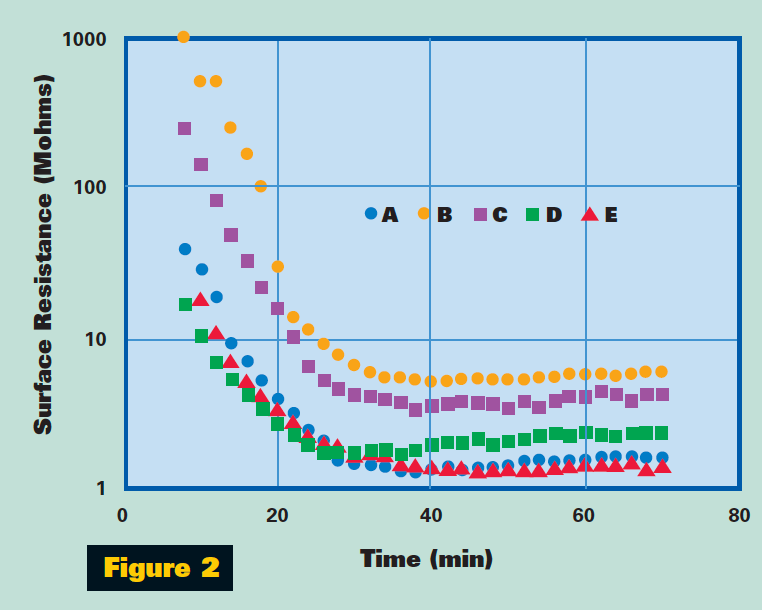
The overall surface condition of the sample insulators was assessed by means of surface resistance measurements involving tests conducted in a fog chamber (as shown schematically in Figure 1). The fog-wetting rate used was 200 g/h.m3 and obtained by boiling water in a vat. Voltage of 1 kV +DC was applied to the insulator cap and the pin was grounded. The leakage current that flows over the contaminated surface of the insulators was then measured as a voltage drop with a digital meter. The surface resistance was calculated and plotted as a function of the elapsed testing time.
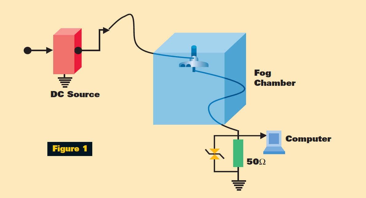
Figure 2 provides the range of values measured for the insulator bells received from the field.
It can be seen that there is quite a significant dependence of the measured resistance on surface condition. For example, those units with damage to the glaze due to permanently burned-in contaminants consistently showed lower resistance than insulators with a normal glaze.
B. Low Frequency Puncture Resistance
Low frequency (60 Hz) puncture tests were performed in oil according to the procedure described in Section 15 in IEC 60383-1.
Only those insulators of Type E from one manufacturer failed, with 7 out of the 14 bells tested being punctured, even though they came from different strings. The failed insulators had been removed from a section of line known to have a high lightning incidence.
These failures occurred at voltages as low as 10 kV. For typical standard cap and pin porcelain insulators, the low frequency puncture voltage is typically greater than 100 kV. Interestingly, most of the punctured units were removed from the high voltage, conductor end of the string.
None of the other insulators failed the puncture test. The maximum voltage applied to the samples was 50 kV for a duration of 1 minute.

Mechanical Tests
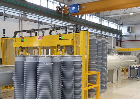
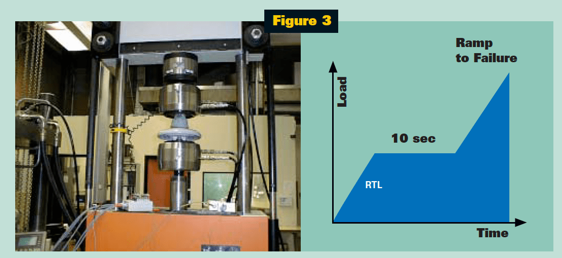
Each sample insulator bell was installed in a universal testing machine as shown in Figure 3 and tensioned to failure. The load was applied gradually until the routine test load (RTL) which was then applied for 10 seconds and subsequently increased until failure.
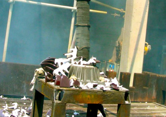
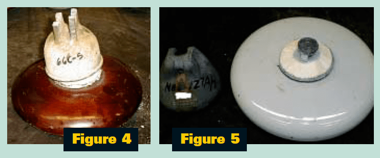
It was noticed that some bells broke at the metal hardware (Figure 4), whereas for others the entire cap became removed from the insulator body (Figure 5).
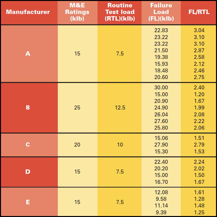
The ratio of the failure load to the RTL is shown in Table 2.
It can be seen that there is a wide variation in the load to failure. However, for insulators from manufacturer E and which had punctured, the mechanical failure load was consistently lower than for other insulators.
The data suggest that a ratio of less than 2 for the FL/RTL may be used as an indicator of ageing for porcelain insulators. Further work in this area is needed and could be of interest of utilities looking for better criteria for deciding when is the best time for replacing old porcelain units.
CLICK TO ENLARGE
Summary
Porcelain insulators are subject to ageing in several ways which can be characterized by both electrical and mechanical measurements. The degree of ageing is highly dependent on formulation and manufacturing details.
This research provides evidence of the existence of porcelain insulators which were in service for over 50 years with very little degradation and others which have changed significantly within only 10 years. Hence, caution should certainly be exercised in making judgements on the longevity of insulators based solely on whether they are ceramic or non-ceramic.