Problems with bushings are one of the leading causes of transformer failure and that means their proper selection can significantly impact transformer and substation safety. Traditional bushing technologies such as oil-impregnated paper bushings (OIP) and resin-impregnated paper bushings (RIP) are long established but still come with certain disadvantages. In the case of OIP bushings, for example, there are safety, reliability and environmental risks. For RIP bushings, moisture ingress during storage is a threat.
This edited article, based on a paper at the 2015 INMR WORLD CONGRESS by Gobi Kannan & Wong Fook Ming of Tenaga Nasional Berhad (TNB) in Malaysia, Daniel Egger & Thomas Schütte of ABB Switzerland and Jan Czyzewski of ABB Poland, outlined production and testing experience with new resin-impregnated synthetic (RIS) bushings. The first part summarized tests performed to assess long-term behavior under stress; the second reviewed early field experience based on a pilot installation in Malaysia.
RIS Technology
With RIS bushings, a synthetic polymer fibre replaces the dense paper utilized in OIP and RIP technologies. This open mesh fabric can be impregnated by alumina or silica-powder filled epoxy resin whose viscosity is much higher than that of traditional impregnation liquids such as oil and pure resin. Powder-filled resins are a proven insulating material with decades of experience across several MV & HV applications and this ensures good electrical and mechanical performance when applied to bushings. Moreover, by using these resins, the condenser core can be moulded directly into its final shape and hardened in a short time. In addition, core drying prior to impregnation is no longer necessary since, unlike paper, polymer fibres absorb virtually no humidity. The silicone elastomer that forms the external part of the insulator can also be directly moulded onto the air side of the condenser body. Finally, the combination of advanced material selection and improved processing capabilities allows RIS bushings uncommonly short production lead times versus other styles of HV bushings.
Oil-to-air transformer RIS bushings with silicone external insulation have now been developed and are commercially available. They fulfil all the specifications required in IEC 60137 (2008) and also the electrical, thermal and mechanical properties of the relevant IEEE standards. These bushings are characterized by a very low dielectric loss factor (tan δ typically below 0.35%), while their electrical design and void-free impregnation process allows partial discharge (PD) free operation up to twice the maximum phase-to-ground operating voltage, specified at a PD measurement background noise of 2 pC.
Such performance, equivalent to state-of-the-art RIP bushings, is significantly better than the minimum specified by the IEC standard (i.e. a loss factor < 0.7% and PD levels of 10 pC and 5 pC at 1.5 and 1.05 times maximum phase-to-ground operating voltage, respectively). At the same time, the creepage distance of the silicone insulators on RIS bushings allows them to be installed even in environments with pollution severity class ‘e’ (i.e. very heavy) according to IEC 60815-1 (2008). Mounting angle can be from vertical to horizontal (0° to 90°) due to the bushing’s dry structure.
CLICK TO ENLARGE
Design Tests
International standards such as IEC require type tests for new product designs and also establish routine test procedures. However, when it comes to new technologies such as RIS, standards cannot provide clear guidance about the testing needed to demonstrate performance. Rather, it is up to manufacturers to establish appropriate test procedures while recognizing that their utility customers may require additional tests in order to approve new equipment installed on power networks.
Boiling Water Test
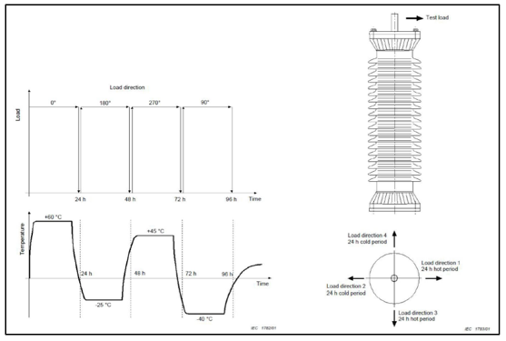
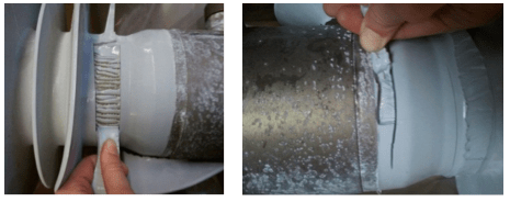
The silicone of the bushing’s external air side insulation does not itself prevent moisture from creeping through to the condenser body. For this reason, an RIP bushing typically features a moisture barrier added between silicone housing and condenser core. For RIS bushings, however, where the silicone is molded directly onto the core, this issue is not a concern. Mechanical integrity of the silicone housing as well as prevention of moisture ingress is verified by means of water immersion testing (e.g. boiling tests). Such testing must demonstrate that there is no de-lamination of the external silicone insulation from the condenser core under stress. Moreover, the test also has to demonstrate that there is no moisture ingress, even though the complete bushing is being boiled with no special protection. A boiling test was performed on three 24 kV RIS bushings in order to test the interface between condenser core and silicone housing. One bushing was pre-stressed thermomechanically according to IEC 60099-4 (see Fig. 1). The bushing was bent in line with specified long-term load while direction of load was altered every 24 h. Temperature cycles were performed in parallel with the long-term test load such that two cycles from -40°C to +60°C were applied with 48 h duration.
CLICK TO ENLARGE
CLICK TO ENLARGE
After pre-stressing, all three bushings were kept fully immersed for 42 hours in a vessel of boiling de-ionized water having 1 kg/m3 NaCl. All three bushings again passed the full dielectric test according to IEC 60137 type test specifications, including lightning impulse, capacitance and tan δ measurement. Afterwards, adhesion of the silicone to the condenser core was tested by cutting into the insulation layer and trying to peel it off. This test demonstrated that the cohesive bonding characteristic of the silicone remained unchanged.
Multi Bending Test
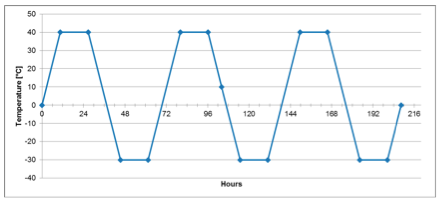
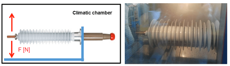
To simulate continuous impact of wind forces as well as the load imposed by free hanging overhead lines, cantilever load and low temperature tests were combined on a 123 kV RIS transformer bushing. The test was performed in cooperation with a German utility according to their internal technical specification. The low temperature test consisted of three temperature cycles from -30°C to +40°C (see Fig. 2). The bushing was bent 25,000 times over 9 days with a bending load of 60% of the cantilever load according IEC 60137 Class II. Fig 3. depicts a schematic and photo of the set-up in a climate chamber. After completion, the bushing again successfully passed the full dielectric type test, including lightning impulse and tightness.
CLICK TO ENLARGE
CLICK TO ENLARGE
Thermal Ageing Test
The temperature class of an electrical insulating material, i.e. its maximum long-term operating temperature, is determined by applying a long-term thermo-oxidation ageing test procedure. The general requirements for such tests are given in the corresponding IEC standard. During testing, samples of the material are kept at different temperatures in ovens with sufficient air supply and circulation. For each temperature, time is registered until the particular diagnostic property of the material (e.g. mechanical strength) reaches some defined end value. Based on the dependence of times registered on ageing temperatures, correlation between temperature and lifetime of a material in service can be assessed. The constant operating temperature that leads to a defined lifetime of the material is then referred to as the temperature index (TI). Relative temperature index (RTI) can also be defined when two materials are tested in parallel: one serves as reference while the second is tested. The indices are comparative. Maximum service temperatures cannot be derived directly from such measured indices without considering all relevant aspects of an application, e.g. how often the temperature is close to the maximum, what is the thickness of the material applied compared with the one tested, etc. The IEC standard recommends that TI value be defined for a lifetime of 20,000 hours.
[inline_ad_2]
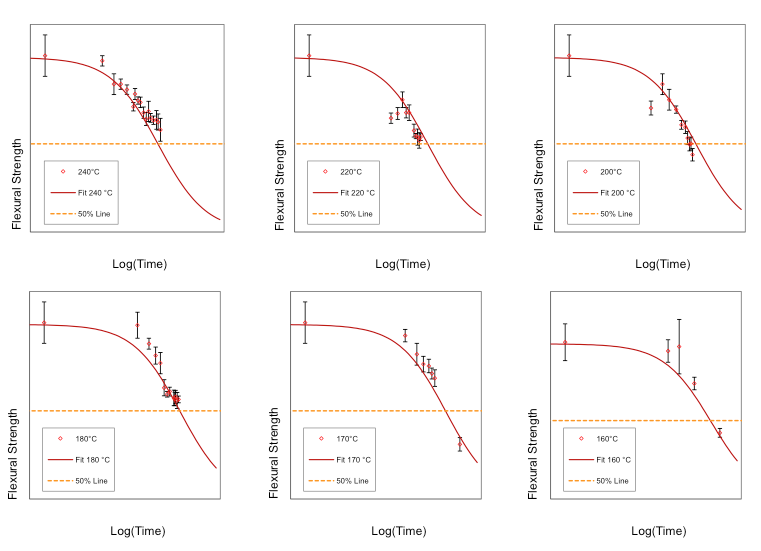
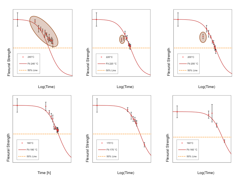
The test to be performed covered forced long-term thermo-oxidative ageing of the RIS material. Samples were aged at 6 different temperatures: 240°C, 220°C, 200°C, 180°C, 170°C and 160°C. The selected diagnostic property here was flexural strength, measured according to ISO 178 at room temperature. The end-point was defined as where flexural strength had dropped to 50% of its initial value. Samples of 80 mm x 10 mm x 4 mm were molded with the epoxy resin and synthetic mesh. Pre-conditioning for 48 hours is required for all samples at the lowest ageing temperature in order to make the test independent of any short-term effects. The result of the test is flexural strength Rm(T, τ), being a function of absolute temperature T and ageing time τ. Preliminary analysis of the data requires identification of a region for each T in which Rm is linear in ln(τ) around the point where the line crosses the line of 50% of initial value of Rm. Crossing point position is assumed to follow the Arrhenius ageing relationship:
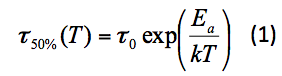 where τ0 is a time constant characteristic for the material, Ea is the activation temperature and k is the Boltzman constant. It is more convenient to also establish a formula to analyse the time dependence of the data as a whole. Although not provided for by the standards, we found that the Woods-Saxon formula, originally used to describe potential of atomic nuclei, plotted against ln(τ), could be applied for this purpose:
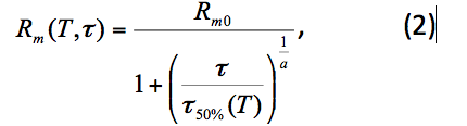
where τ50%(T) is the ageing time at temperature T until the diagnostic property drops to 50% of its initial value according to equation (1). τ is the ageing time and a is the fit parameter. This function results in the ageing curve being approximately linear in the range of the diagnostic property between ca. 75% and 25% of its initial value. The restriction of the correlation of (1) and (2) is that the slope of the linear part of the ageing curve, which is determined by the parameter a, is identical for all ageing temperatures. This is in agreement with the assumption that the Arrhenius relation with the same activation energy describes ageing, not dependent on the assumed end-point value of the diagnostic property.
CLICK TO ENLARGE
CLICK TO ENLARGE
For the above reasons, it was decided to remove the 240°C point from the analysis. Correlation of the data points from 160°C to 220°C is shown in Fig. 5. The χ2/ DOF is 1.32 and indicates consistent fit. Temperature indices at defined lifetime τ50% can be directly derived from formula (1) and when the correlated parameters are known. The IEC standard requires applying the relevant temperature index at 20,000 h. It is, however, more common to apply the maximum constant operating temperature value at 60,000 h. This is also suggested by the corresponding UL standard when no reference material is tested in parallel. It was cross-checked that the difference between the temperature indices calculated using the correlation between equations (1) and (2) and those obtained from the full statistical analysis described in IEC 60216-3, is smaller than the statistical uncertainty of the results.
[inline_ad_3]
CLICK TO ENLARGE
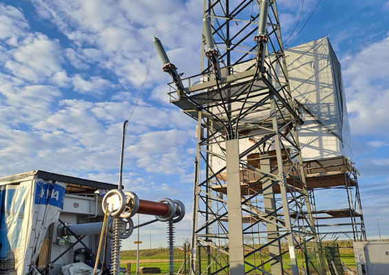
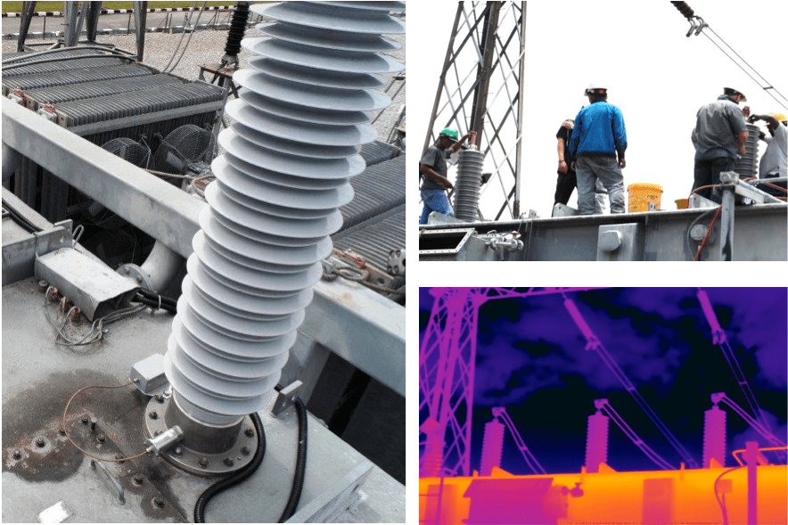
Field Experience at TNB
RIS bushings were installed in Apr 2014 at a 132 kV substation as part of a pilot project with TNB in Malaysia. A real-time monitoring system for the bushings was installed to gain experience over 6 months.
On-line Monitoring Results
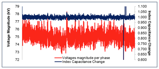
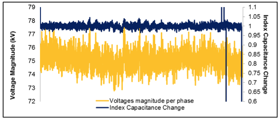
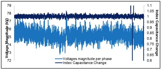
Measurement of capacitance and voltage waveform for phases A to C (Figs. 6, 7 & 8) were recorded over 6 months using the continuous monitoring system. In regard to stability of capacitance value, relative change against the nominal value was recorded as were any overvoltage conditions in the system. Prior to this test, agreed acceptance criteria for the bushings was a maximum permitted ± 3% permanent change versus initial value over the entire evaluation period.
The measuring principle for this system incorporated two main parameters that included voltages of all windings per phase as well as the index of capacitance change, measured using voltages from 3 bushings that are coupled by special measuring impedance. Voltage signals are compared such that any asymmetry between voltage signals indicates a change in bushing capacitance. The index of capacitance change during the on-line measurement on phase A, for example, was calculated based on the formula:
![]()
CLICK TO ENLARGE
CLICK TO ENLARGE
CLICK TO ENLARGE
Summary of Monitoring Parameters
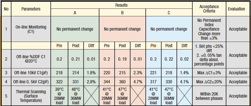
Table 1 summarizes the parameters measured over the course of the evaluation period and also compares these with acceptance criteria by both the manufacturer and the user, TNB:
Table 1: Results of On-line Bushing Monitoring Measurements
Objective: TNB Pilot Project Justification
1. The reliability of a HV bushing depends greatly on local conditions. In a humid tropical service environment with temperatures averaging 38°C (as typical in Malaysia), a bushing will experience greater stress than in cold climates. High electric field gradients and high working temperatures contribute to accelerated ageing of insulation. The new RIS bushing technology should be able to withstand these higher stress levels. The impact of environment on performance was therefore one of the aspects to be evaluated in this pilot project.
2. Dissipation factor, capacitance and partial discharge measurement are parameters used to assess degradation of the insulation system in OIP and RIP bushings. It is well known that any deterioration in paper bushing insulation will produce moisture and cause an increase in dielectric losses and consequent increase in power factor. At the same time, ageing of fiber insulation is not yet well understood. While existing measurement techniques can be used on RIS bushings, acceptance values could be different due to the different insulation used. This research will therefore help determine efficient techniques or test methodologies to determine the health of RIS bushings versus those used with conventional bushing technologies.
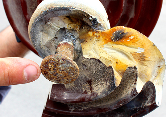
3. Explosion of bushings can result in significant collateral damage to assets and impact system reliability. Indeed, surveys have shown an increasing number of bushing failures. In addition, almost 70% of all bushing failures result in a power transformer fire, with most caused by insulation related issues. Given this, power utilities are interested to adopt and study any bushing technology that promises to be immune to moisture ingress, while also providing the highest operational safety.
4. Installation of the new RIS bushings on a power transformer should improve its reliability as well. In the case of a new transformer, installation of RIS bushings will not cause a problem as any modification on the transformer can be done during its design and manufacturing process. However, it is important to address the potential impact of retrofitting new RIS bushings onto existing transformers. This study will enable the project team to address and learn more about any issues related to the effect of new RIS bushings applied to existing transformers.
5. RIS technology is also of interest to TNB because of the comparative ease of storage requirements. This is in contrast to RIP bushings that require special storage procedures for the oil end side due to its hygroscopic nature (e.g. oil containers). Storing RIS bushings might save space and result in lower life-cycle costs compared with RIP bushings.
6. RIS technology also offers benefits due to its shorter lead manufacturing time compared to RIP bushings. This might prove attractive, especially for refurbishment, repair and emergency restoration work as it can save significant delivery and downtime.
Based on the findings of this pilot project, TNB concluded that the RIS bushing technology has proven reliable and fully complies with agreed acceptance criteria. Given this, the technology will be proposed for future use in the system at installations up to 170 kV.
[inline_ad_4]
Summary
Since the launch of RIS technology, additional experience has been gained. Accelerated ageing tests for moisture penetration, mechanical bending and thermooxidation have shown that RIS technology guarantees high performance even in harsh service environments. In the boiling water test, RIS bushings were pre-stressed mechanically and thermally and exposed to boiling water for 42 hours. Afterwards the bushings passed a full type test procedure according IEC 60137. In the multibending stress test, a bushing was bent in x- and y-directions for 25,000 bending cycles with 60% of the test load according IEC 60137. Also, after this test, a full type test procedure according IEC 60137 was passed. The accelerated thermooxidation ageing test proved that the performance of the RIS bushing fulfils temperature class E according IEC 60137.
There are already several hundred RIS bushings in operation. TNB Malaysia, for example, agreed to a reference installation that was monitored with an on-line monitoring system for 6 months. Based on the results, the RIS bushings under evaluation fulfilled all relevant requirements and offered excellent field performance