While several atmospheric parameters can affect the dielectric strength of external insulation, relative air density and absolute humidity are considered the most significant. This edited past contribution to INMR by T&D expert, Alberto Pigini, focused on the former, which plays a key role in developing transmission systems at high altitude
Studying the role of air density started over a century ago but accelerated with development of EHV and the need to optimize line and substation design under switching overvoltages. High altitude tests on large clearances were carried out in the U.S. (1967 Phillips and al.: tests up to 3500 m), Japan (Harada and al. 1970: tests up to 1850 m) as well as Italy, South Africa and Mexico (Pigini and al. 1989: comparative tests up to 3000 m). More recent research has come from the need to optimize design of UHV projects at high altitudes in China, with systematic testing in places such as Kunming (2100 m), Xining (2260 m, Qinghai (3000 m and Tibet (4300 m). Climate chambers have even been built to simulate altitudes up to 6000 m.
There have been different approaches in the standards on how to account for changing air density with altitude. IEC 60060-1, for example, conceived for correcting laboratory tests, uses: U=Uo*K, where U and Uo are the dielectric strengths at high altitude and at standard atmospheric conditions respectively and where K is the air density correction factor given by K=δm with δ being relative air density at high altitude. IEC 60071-2, conceived for insulation coordination, makes direct reference to site altitude (H), being δ under simplified assumptions related to H by δ=e(H/8150). The main problem is determining the parameter m, which depends on type of voltage stress, insulation configuration, type of insulator and environmental conditions (e.g. dry, wet, contaminated).
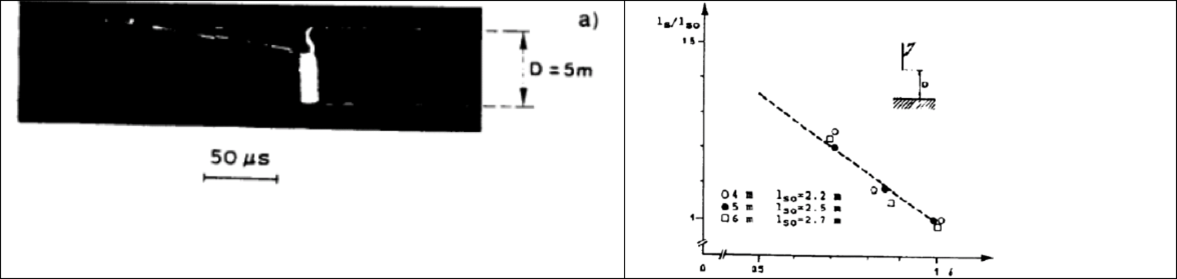
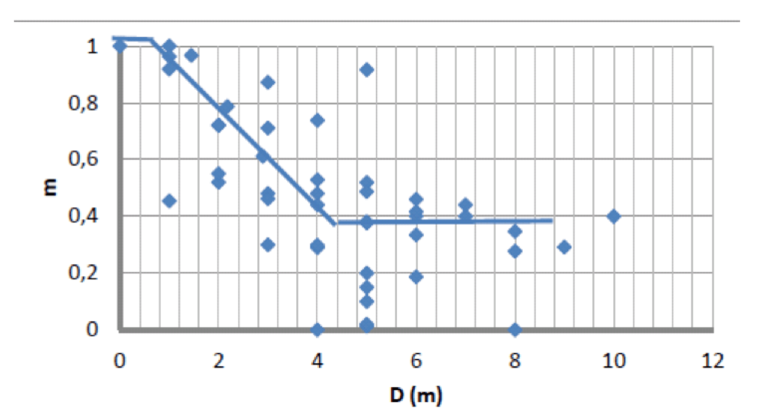
Fig. 1 shows an example of the range in ‘m’ values found by various researchers for positive Switching Impulse for different configurations with and without insulators. Results are plotted as a function of gap clearance. In this same chart, the continuous curves represent the correction approach adopted in the old IEC 60 relating m to clearance. The new approach under IEC standards 60060 and 60071, where I contributed, attempted to better rationalize available information (then limited to 3500 m) relating the factor m to stress parameters instead of clearance. However, the approaches in the two are sometimes contradictory, even if starting from the same basic data, and they are difficult to apply as well. Moreover, they do not take into account new information from tests up to 5000 m. An urgent need therefore exists to update and harmonize such correction approaches while taking into account latest results, as recommended by IEC and supported by CIGRE, where two new working groups look at the influence of altitude on clean insulators (WG D1.50) and polluted insulators (WG D1.44).
Several suggestions to optimize the new approach have been proposed:
1. Influence of air density is generally a minor part of breakdown/flashover voltage: a small inaccuracy in measurement, in configuration simulation or in voltage parameters can lead to high inaccuracies in the parameter m when comparing results at different altitudes. Comparative tests at various altitudes must therefore be designed and carried out accurately.
2. Best not to overlook the existing range of historical experimental data, using newly generated data to better integrate and implement them.
3. Many tests have been made and are still being made on basic configurations such as the rod plane under dry conditions, where influence of air density can be much different from that of actual insulator configurations. Additional data for actual configurations should be provided as much as possible.
4. One of the most important environmental conditions to be considered in design is performance under rain, which can dramatically reduce insulator strength depending on voltage, configuration and type of insulator. Since the relative influence of air density on insulator strength can change under rain, there is a need for more data to better understand how (e.g. by researching performance of insulators under DC voltage and rain).
5. Since pollution is the governing design stress for DC systems, additional data is needed on the influence of air density on pollution flashover of hydrophilic as well as hydrophobic insulators as a function of their geometry.
6. Due to the complexity of the phenomenon and the many parameters involved, understanding the influence of air density can be made easier if accompanied by analysis of its impact on the physical processes leading to flashover, including its influence on the streamer and leader phases.
7. Because of the complexity referred to above, it does not seem possible to arrive at one approach that is both accurate and relatively simple. In the end, simplicity should be the goal for engineering applications and the required accuracy could be assessed by looking at the typical dispersion in experimental findings.
8. As much as possible the ‘formal’ approach should be the same for all various standards in order to avoid the confusion of present standards that often express the same concept and give similar indications but use different language.