[inline_ad_block]
Growing interest in parallel routing of AC and DC circuits on the same towers of what are referred to as ‘hybrid overhead lines’ could cause both AC and DC voltage components (known as composite voltages) to appear on line insulators. Up to now, knowledge about insulator performance under such composite voltage stress is still relatively limited, as reported in CIGRE paper D1-112 during the recent 2016 General Session.
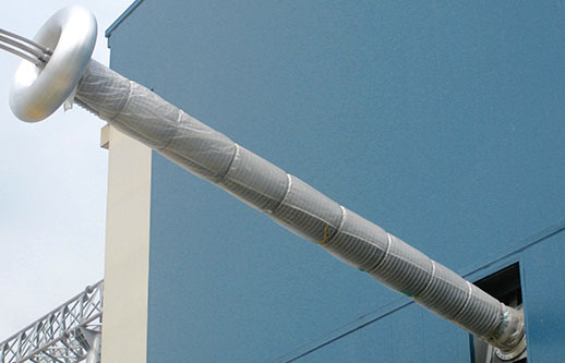
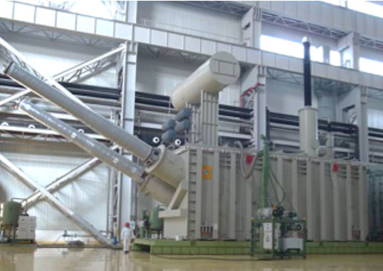
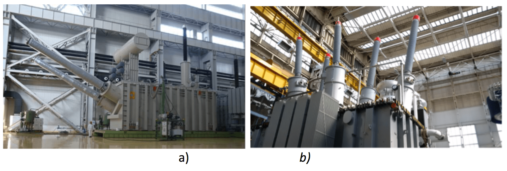
The problem becomes more complex still in the case of converter transformer bushings. This column will focus on the situation for bushings installed outdoors, taking into account potential impact of severe service conditions such as pollution and icing.
CLICK TO ENLARGE
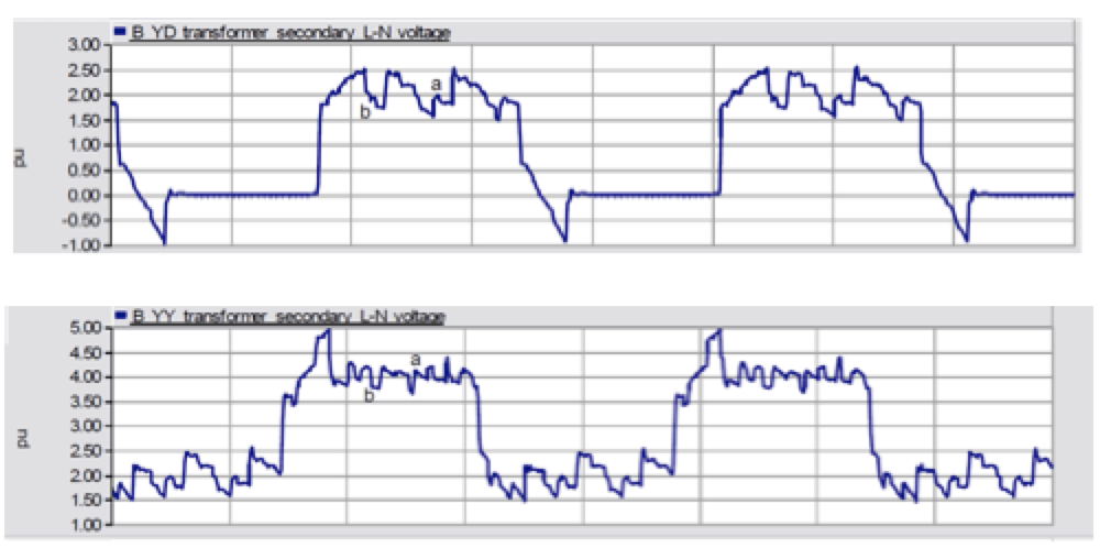
The steady state voltage at bushings and on post insulators as well as other connected apparatus results as a combination of DC and different harmonics (as shown by the examples in Fig. 1).
CLICK TO ENLARGE
Nowadays, results of tests with voltage stresses as in Fig. 1 are not available nor even feasible for actual HV apparatus and insulators. As such, it is necessary to define an equivalent voltage stress to be taken as the basis for design and testing purposes. Indeed, this is the approach followed by the dual logo IEC-IEEE Standard for DC bushings (IEC/ IEEE 65700), which makes reference to design and testing of external insulation to an equivalent voltage U1, defined as ‘rated voltage’.
In practice, standard 65700 allows for simplification. It assumes that actual stress can be represented by considering only the DC component, Udc, and the AC component Uac (rms value), while disregarding other harmonics. Peak voltages of short duration, such as those in Fig. 1, can be assimilated to overvoltages and the above peaks are not considered in engineering practice to verify performance under steady state conditions (e.g. under pollution or icing). Then, voltage U1 is evaluated as the square root of the sum of the squares of the values of the AC and DC components, as follows:
U1 = √(Udc2 + Uacrms2)
The Standards state that U1 is: The rated continuous DC voltage or the r.m.s. value of the combined DC and AC phase to earth voltage, depending on the point of application of the bushing in the electrical scheme (kV). This leaves some degree of uncertainty on the type of voltage to be selected for design and testing. Thus, the problem remains whether U1 should be assimilated to an AC or DC voltage, especially considering the impact on dimensioning external insulation under pollution and icing – which for DC is far more severe than for AC.
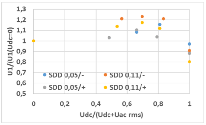
Recent pollution tests made on small insulator samples by applying different proportions of AC and DC voltages have indicated that the flashover voltage under the mixed voltage (AC+DC) is higher than the value expected under pure AC across a wide range of DC/AC values (see Fig. 2). The figure makes clear that, in the range of interest for converter bushings, the flashover voltage UF value with composite voltages is generally higher than the value for the DC=0 case (i.e. only AC component). Testing with only AC voltage (DC=0) can then lead to a conservative approach.
Adopting AC voltage as an equivalent voltage for design and testing is also supported by a qualitative analysis of voltage shape in Fig. 1. The shape appears closer to an oscillating than to a direct voltage.
However, since available results are based on relatively short insulators, additional investigation on larger and more representative samples are recommended in order to verify the above assumption.
CLICK TO ENLARGE
Alberto Pigini