Introduction
The use of composite insulators is increasing as the market accepts the technology. Composite insulators for transmission line applications are today well accepted and are winning an increasing share of the market. As well for surge arresters were the majority sold today is with non-ceramic solutions. Lightweight, superior pollution performance and increased safety are some advantages of composite insulators. Composite hollow insulators for high voltage apparatuses such as high voltage live tank breakers are comparatively new. In other applications like dead tank breakers, composite insulators have been used for about 15 years. As the acceptance for composite insulators in applications for HV apparatuses is increasing, the volume is also increasing. There is however very little information in the literature on aging of composite insulators used on high voltage apparatuses, in particularly on voltages equal to or higher than 145 kV.
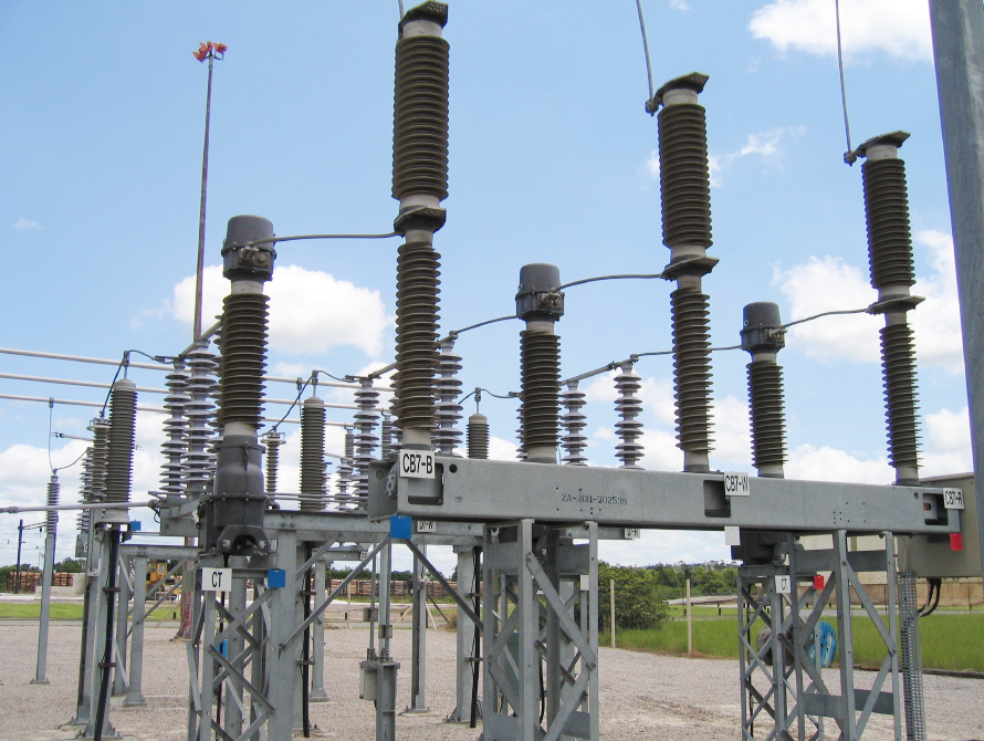
It is not unusual today that utilities choose to buy all the apparatuses with composite insulators when renovating or building new substations. An example from a substation in South Africa where all the electrical apparatuses are composite can be seen in figure 1
Silicone rubber as housing material for high voltage transmission lines has proven to have excellent performance under different conditions such as coastal, desert and industrial environments. However, silicone rubber is, as most polymers, sensitive to electrical discharges. Due to this different additives are added to the formulation in order to protect the polymer. Another critical parameter is the design and testing of the insulator and its material. Testing and minimum requirements of the material itself is specified in [1] for the most important properties. There is some work remaining on certain properties such as corona and hydrophobicity.
Test requirements of hollow composite insulators are specified in IEC 61462 [2]. IEC 61462 specifies both electrical and mechanical tests as well as some aging tests. What is not specified is testing the performance under pollution. This is handled by IEC 60815 [3]. IEC 60815 is under revision and will, when revised, consist of 5 parts. Part 1 (general definitions) and part 2 (ceramic insulators) are well on their way. The work on part 3 (composite insulators) has just started and is expected to be finished within a few years.
Silicone rubber is a generic name commonly used to explain the type of housing material used. Other names used are abbreviations such as LSR (Liquid Silicone Rubber), RTV (Room Temperature Vulcanising silicone rubber) and HTV (High Temperature Vulcanising silicone rubber). Usually the process of producing the insulators sets the requirement on which type of rubber to use.
Different insulation concepts are today used within ABB. For the majority of medium voltage (MV) apparatuses such as instrument transformers, fuses, switches etc epoxy is the main insulating material. Today this has been further developed using the hydrophobic epoxies. For MV surge arresters and MV cable terminations silicone rubber is the dominating insulating material. For high voltages (HV) silicone rubber is the only non-ceramic solution.
ABB has today supplied over 1500 high voltage live tank breakers (LTB), over 6500 dead tank breakers (DTB) and over 40000 high voltage surge arresters with very good service experience to totally over 100 countries around the world.

Materials and interfaces
Silicone rubber
Silicone rubbers used as housing materials usually consist of a number of different additives for obtaining desired properties. The silicone polymer, polydimethyl siloxane (PDMS), by itself is relatively weak when cross-linked, forming a brittle transparent rubber. Thus it is necessary to reinforce the polymer by adding very fine, high surface area fillers. These fillers are usually surface-treated to become more chemically compatible with the silicone polymer. It should be noted that filler treatments as well as filler particle sizes are what tend to distinguish different silicone rubber formulations. The most common reinforcing filler used is different types of silica. For improving tracking resistance, alumina trihydrate (ATH) is often added. Most of the commonly used fillers tend to reduce the price of the silicone. Moreover pigments for obtaining a desired colour as well as silicone oils for processability, are added. Finally curing agents are added for vulcanization (cross linking).
Vulcanization/Curing of Silicone Rubber
Traditional curing agents of silicone rubber compounds are organic peroxides which, when heated, decompose to form free radicals that react with the polymer chains, forming crosslinks. Peroxide curing systems generally have a lower price compared to other curing agents, have a long shelf life and moreover some peroxides can be cured in hot air at atmospheric pressure. A disadvantage is that post-curing usually is required to remove acidic degradation products from the peroxide.
In addition-curing systems, specific chemical groups in the polymer chains reacts in the presence of a noble metal catalyst (usually platinum). No by-products are formed in this highly specific reaction, removing the need for a separate post-curing step. The rate of crosslinking can be accurately tuned by the addition of inhibitors (reducing reaction speed) and accelerators. Drawbacks are higher price compared, to the peroxides. However, considerably less volume is used as compared to the peroxide solution. Moreover it is more critical to have a correct priming procedure to achieve a proper adhesion, compared to the peroxide cured rubbers which contain more reactive groups available for obtaining chemical bonding to the substrates.
Silicone Rubber Compounds for OutdoorInsulation
High Temperature Vulcanising (HTV) silicone rubbers are mixtures of a siloxane polymer with high molar mass (long polymer chains) and relatively high amounts of inorganic fillers (up to 50 wt. %), of which the major component is ATH. HTV systems are usually cured using peroxides, but addition-curing HTV systems are increasingly used as well.
Liquid Silicone Rubbers (LSR) silicones are two components addition-curing systems with lower viscosity allowing them to be injected/ pumped into moulds after an initial mixing step. Curing occurs at elevated temperatures. The lower viscosity is obtained using siloxane with lower molar mass, in combination with lower amounts of filler, compare to the HTV systems. Usually only reinforcing silica is used, while the addition of larger amounts of ATH would lead to a too high viscosity. The lower pressure used during injection puts lower demands on the moulds, compared to the high pressure used for HTV materials.
Room Temperature Vulcanising (RTV) silicone compounds are used for some outdoor applications. The RTV-2 silicones have even lower viscosity than the LSR rubbers and are normally used for casting (pouring the silicone into moulds). These materials can be crosslinked at room temperature or higher by adding the second component. Finally, RTV-1 silicones are one- component systems that are cured by reaction with moisture in the air and are often referred to as silicone glues.
Manufacturing Technologies
Hollow composite insulators can be made in several ways, including injection moulding, casting and spiral wrapped-layer techniques. Also several types of silicone rubber materials such as LSR, RTV and HTV can be used in combination with the various production technologies. The specific formulation of the silicone rubber has to be adjusted to suit the chosen production process. When a formulation and a production process is chosen the properties of the material can only be varied within certain rather narrow limits without jeopardising the quality of the production. Depending on the volume i.e. number of insulators per type of apparatus, there are advantages and disadvantages with the different manufacturing techniques.
HTV rubbers are usually referred to as having a higher resistance to tracking and erosion due to that they are heavily filled with ATH. These clay-like high viscosity compounds can be processed using either injection moulding or by extrusion processes. In both techniques the HTV compound is softened/ degassed in an extruder and subsequently either injected and cross-linked in a mould at elevated temperature (injection moulded) or shaped into a shed-like profile (an extrusion process).
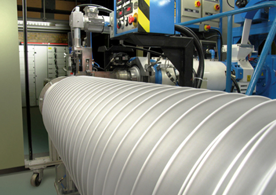
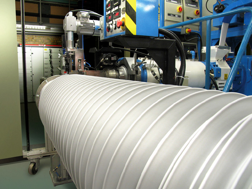
Producing hollow core insulators by the extrusion process offer several advantages, where the HTV is applied and helically extruded onto glass-fiber reinforced epoxy tubes (figure 2). The silicone housings are then cured in large ovens. Using this process the shape of the shed, which is determined by the nozzle of the extruder, can be easily changed according to customer’s demands. Moreover a wide range of hollow core insulators having different diameters and lengths can be easily manufactured. The drawback of the extrusion technology is that currently only filled HTV rubbers can be used, in order to maintain a stable shed profile before cross linking has been performed. This requires a high viscosity material.
In the alternative production technology for hollow core insulators – injection moulding, a low viscosity LSR rubber is commonly used, in order to avoid to high injection pressures. Thus it is not possible to add large amount of fillers as for HTV rubbers. Due to this fact, this method gives a higher price on the silicone rubber. Moreover expensive moulds are required for every different tube diameter and shed design. However, this process is increasingly profitable with increasing numbers of standardized objects, compared to the extrusion process.
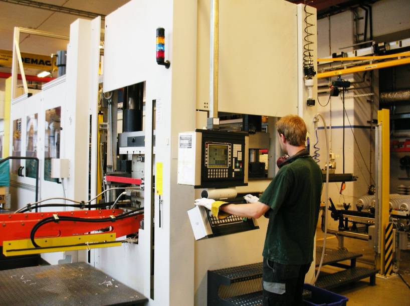
Injection moulding of housings for smaller components, such as surge arresters or line insulators, can be performed using either HTV or LSR rubbers. An example of equipment for injection moulding of HV surge arresters with HTV can be seen in figure 3. Again the costs of the moulds for HTV systems are higher compared to the moulds for LSR systems due to the higher injection pressure.
Testing of Materials for Outdoor Insulation
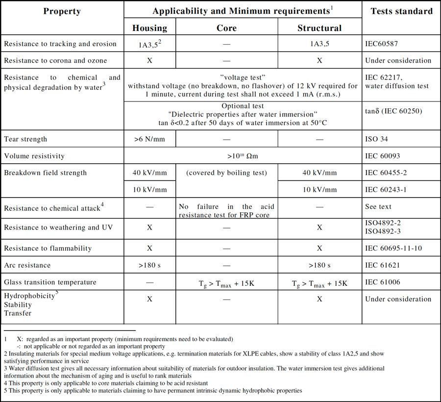
Test methods and minimum requirements have not been available for materials used in outdoor electrical applications. As the knowledge on the use of polymeric materials in high voltage applications has increased with time also the knowledge on minimum requirements has increased. This can be seen in technical brochure TB 255 [1]. There the collected knowledge on polymeric materials have been gathered and summarised. The minimum requirements and applicable test methods specified in [1] can be seen in table 1. Also in the future standard IEC 62217 [4] some of the minimum requirements are defined. However, there is a lack of knowledge regarding test methods and minimum requirements for properties such as hydrophobicity, resistance to corona and ozone, flammability and weathering and UV. For some of these properties like transfer and loss/recovery of hydrophobicity, the Chinese standard, DL/T 810 – 2002, specifies minimum requirements and test methods [5]. As this standard is in the Chinese language it is not so easily accessible. Parts of it translated in English can be found in [6, 7]. It is clear from the data available today that more work on minimum requirements and test methods are needed in order to define these properties. The ongoing activities within CIGRE D1-14 aim to clarify this.
From studies performed within ABB, it can be concluded that excellent properties could be obtained with any of the vulcanisation techniques studied if properly formulated. Differences between materials from alternative rubber suppliers had more impact on the insulator production processes than on their infield use.
It should be stated that a good material does not necessary mean a good insulator. It is very critical that the insulator is correctly dimensioned as will be discussed in more detail below.
Interfaces
An insulator consists of several microscopic and macroscopic interfaces. It is known both through testing and service, that the most sensitive parts of the insulators are the interfaces. Efforts should be done to minimise the number of interfaces on the insulator. The long-term stability of these interfaces is of crucial importance for the functionality of the insulator.
It has been shown earlier that the majority of replaced insulators have failed in the weather shed-rod interface [8], which clearly indicates the importance controlling parameters related to the macroscopic interfaces.
Different technologies for non-destructive (NDT) evaluation of the macroscopic interface are under investigation. Technologies under evaluation is:
• computer tomography
• different x-ray techniques
• laser shearography
• different ultra sonic techniques
• partial discharge measurements
So far, the investigation shows promising results regarding NDT of hollow composite insulators. NDT of every insulator is not feasible but checking samples in production will be possible.

Insulators
To be successful in the business of composite insulators one has to find ways to
• exploit the inherent properties of the material in the corresponding application
• realise new integrated solutions fast and safe
Looking from the point of view of a manufacturer of this can only be done in two ways. Either you go into a close collaboration with a supplier of insulators or you manufacture it by yourself. The manufacturers of electrical power equipment have done this in different ways. However, ABB are doing it both ways. Since 1998 ABB has its own production unit in order to utilise and implement the advantages with composite insulators and at the same time ABB is buying insulators from other suppliers.
Besides these technology oriented factors it is decisive to find ways to give potential customers confidence in the long-term stability of the insulators. One of the ways is showing long term experience from service and test stations. Part of ABBs experience can be found in this article and in other related articles [9, 10].
Another important aspect is to look from the viewpoint of the electrical apparatus rather than looking on individual parameters of the insulation. There have been tendencies from a research perspective to try to limit certain aspects of the insulation based on individual results, which if looking on the complete insulation system will be a disaster. The apparatus is an insulation system and not a set of individual insulation’s. Thus, the interactions between the insulation systems have to be known as well.
Design
A crucial issue raised at an early stage is the design of the shed profile. Questions such as inclination of upper and lower part of the shed, radius at the tip of the shed, distance between sheds, overhang of the sheds, creepage distance etc. The length and diameter of the insulator are usually governed by the application, which means that variations in the creepage distance have to be done by adjusting the shed profile.
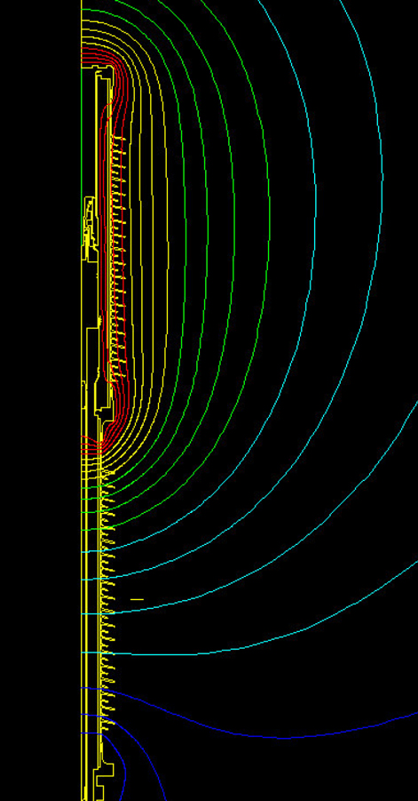
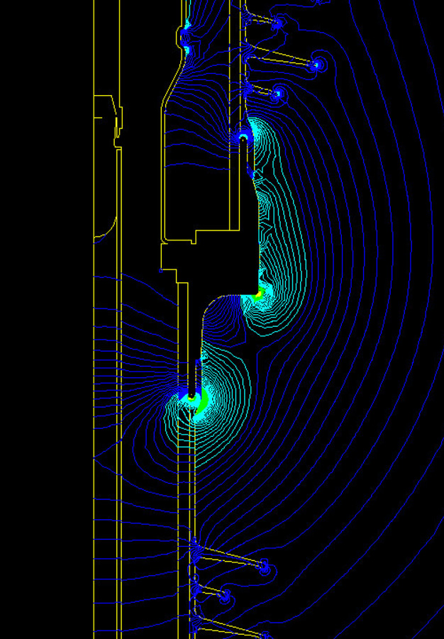
To a certain extent these parameters are decided by environmental factors such as pollution, rain etc. However, many of them are related to the design of the electrical apparatus. Applying dimensioning criteria such as electric field (figure 4 and 5) will inevitably lead to a certain design of the shed profile that on the other hand might not be suitable for production. Thus, the design of the shed profile has to be a compromise between the different factors affecting the performance of the insulator and the chosen production method.
Another critical issue is the calculation and dimensioning of the electric field. An example can be found in figure 4 where the equipotential lines around an LTB in closed position are shown. Correct modeling of the electric field with the apparatus inside is of crucial importance in order to ensure proper function and quality. The design of the mid flange of the LTB can be seen in figure 5 including the distribution of the electric field. The highest electric field is on the edges of the flange, in particular around the end of the flange. The electric field along the surface of the insulator is what governs the aging process.
LTB.
Pollution Tests
The pollution was applied by wind and the test was done cycling fog, rain and dry periods. 84 kV phase-to-earth was applied during the whole cycle that lasted 100 minutes and the cycle was repeated 4 times. No difference could be found between different manufacturers. Even with as high pollution levels as ESDD = 0,7 mg/cm2 and NSDD = 0,2 – 0,7 mg/cm2 all test objects passed the withstand test. As the voltage was ramped to find the flashover value a clear influence of the creepage distance could be seen. The flashover voltage for the insulators with the shortest specific creepage distance (15 mm/kV) was only 7 – 14% higher above the nominal voltage. However, the recommended specific creepage distance according to IEC 60815 for these pollution levels is > 31 mm/kV. No clear influence of the shed profile could be found but there was a tendency to more accumulation of pollution with large inclinations of sheds.
Switching Impulse and AC Test Under Rain
Also in switching impulse and AC test under rain it was not possible to detect any difference between types of insulator (helical/”standard”). There was no influence of the creepage distance on the flashover voltage under SI and rain.
A clear relationship could be found between the SI flashover voltage and the shed distance. The flashover voltage increased with increasing distance between sheds. The best performance was achieved with an alternating shed profile. The physical reason is that with short distance between sheds the water will bridge the gap and cause a partial flashover. With an alternating profile this is avoided.
Even though one of the helically shaped insulators had almost no inclination on the sheds there was no problem with water running along the helical profile, both under hydrophobic and hydrophilic state. The water drops still falls of the sheds along the insulator.

Products with Composite Insulators
ABB today offers a complete range of high voltage electrical apparatuses using different types of composite hollow insulators manufactured by casting, extrusion moulding or injection moulding.
Products that are injection moulded are surge arresters, both MV and HV. As mentioned above this production method is beneficial for large number of insulators and small volume of silicone rubber. A smaller volume of the MV surge arresters is casted.
Casted products are mainly used in the dead tank breakers (DTB) and GIS applications. In DTB applications also extrusion-moulded type of insulators are used. In live tank breaker (LTB) applications mainly the extrusion-moulded type of insulators are used.
As regards to volumes, ABB has sold and installed over:
• 40000 HV surge arresters
• 50000 hollow composite hollow insulators for DTB, GIS and LTB applications
The HV apparatuses are installed in over 110 different countries all over the world in different climate zones and the service experience is extremely good.
The largest long term potential relies on the ability to fully utilise specific properties of composites and polymers in complete new design of products. For being able to exploit this potential the interaction between specialists and product design people is a key issue.
Today, in many cases the customer can choose between porcelain or composite insulators i.e. the insulators are exchangeable one-to-one. However, in some applications ABB has now taken the step to full composite solutions. One example of this is the disconnecting circuit breakers (figure 6). Here the design requires composite insulators. This in order to minimise the leakage currents over the breaker pole since it is also acting as a disconnector.

in Hemsjö substation.
Another example of how new materials and production technologies enables new functionalities is the unconventional shed design of the new dry AC capacitor, Dry-Q (figure 7). Here the injection moulded LSR rubber made it possible to produce very thin sheds, primarily designed for cooling, while the traditional function of the housing is still maintained.
It is most likely that the future development of high voltage apparatuses will move further in the direction of full composite solutions and we will see more products were the only alternative is composite insulation.
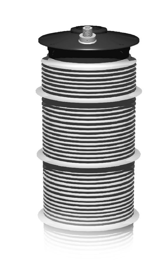
with silicone sheds on a tube of PE

Conclusions
ABB today offers a complete range of high voltage electrical apparatuses using different types of composite hollow insulators manufactured by casting, extrusion or injection moulding. Today, over 50000 composite hollow insulators and over 40000 high voltage surge arresters with silicone insulation have been delivered and installed in various high voltage applications and climates.
As a supplier of high voltage equipment one have to possess a lot of knowledge on how to dimension the products with composite insulators. The silicone materials used in ABB’s high voltage equipment are all approved according to relevant IEC and ANSI standards as well as the requirements set by CIGRE. The silicone materials have also proven their good performance at test stations in severe climates and commercial installations all over the world irrespectively of the type of material.
The insulators and high voltage apparatuses have been tested in accordance with standards and fulfill the requirements specified.
References
[1] CIGRE WG D1-14, “Material properties for non-ceramic outdoor insulation – state-of-theart”, CIGRE TB 255, 2004
[2] IEC 61462 “Composite insulators – Hollow Insulators for use in outdoor and indoor electrical equipment”
[3] IEC 60815 “Guide for the selection of insulators in respect of polluted conditions”
[4] IEC 62217 “Polymeric insulators for indoor and outdoor use with a nominal voltage greater than 1 000 V – general definitions, test methods and acceptance criteria”
[5] DL/T 810 – 2002, Technical specification of ± 500 kV HVDC composite long rod insulator (China Electric Power Industrial Standard)
[6] Liang Xidong, Wang Shaowu, Su Zhiyi, Experience with Composite HVDC and HVAC insulators in China: From Design to Operation, World Conference & Exhibition on Insulators, Arresters and Bushings, pp 15-22, Marbella, 2003
[7] Wang Xun, Liang Xidong, Zhou Yuanxiang, Cheng Zixia, Li Chi, Yin Yu, Four Parameter Method for Hydrophobicity Judgement and Mechanism of Hydrophobicity Transfer Property, Proceedings of the 7th International Conference on Properties and Applications of Dielectric Materials, pp 1222-5, vol. 3, 2003
[8] Kikuchi et al., “Survey on the use of Nonceramic Composite Insulators”, IEEE Transactions on Dielectrics and Electrical Insulation, Vol. 6, No. 5, 1999
[9] Windmar, D., Hillborg, H. and Jansson, F., Aging on Composite Hollow Insulators for High Voltage Circuit Breakers: Experience from Testing and Service, International Symposium of High Voltage Engineering, Beijing, August 25 – 29, 2005
[10] I. Gutman, L. Stenström, D. Gustavsson, D. Windmar and W. Vooslo, “Optimized use of HV composite apparatus insulators: field experience from coastal and inland test stations”, paper A3- 104, 40th CIGRE session, Paris, France, 2004
Address to the author:
Dan Windmar
ABB Power Technologies
High Voltage Products
SE-771 80 Ludvika
Sweden
e-mail: dan.windmar@se.abb.com