The decision to replace end-of-life utility assets can be challenging since several competing factors and methodologies all need to be considered. Due to their strategic importance and large population, transmission line insulators are among the assets for which this process can be especially difficult.
FortisBC serves customers across British Columbia with some 7300 km of 63 kV, 138 kV, 161 kV and 230 kV overhead lines, most utilizing wood pole construction. In the past, the normal service life of these poles was about the same or less than that of the porcelain and glass insulators installed on the network. Replacement was therefore a relatively simple matter of exchanging insulators whenever there was external damage to them or when poles reached their end-of-life, as determined during routine inspections.
However, with recent application of polymeric insulators to this network combined with adoption of more durable structures made of steel, what once seemed a relatively straightforward decision has become complex. Now, structures and insulators can have significantly different service lives.
This edited contribution to INMR by Aram Khalil-Pour, Director of Engineering Services & Asset Management at FortisBC, in cooperation with Staff Engineer, Kevin Kendal, reviews one such case and the testing and other considerations that went into deciding on insulator end-of-life.


Monitoring the condition of in-service insulators is a constant requirement to obtain metrics on when replacement may be needed. Deciding on optimal frequency of such testing is often made according to a schedule based on number of years in service and then some pre-established repeat period thereafter. A different approach involves waiting either until visual defects are detected or until failures start to occur. Selecting the timing for testing depends on relative costs and degrees of acceptable risk and both need to be evaluated based on a line’s criticality.
Testing generally requires removing sample insulators from service and completing some form of destructive testing. While there do exist live-line test techniques, these do not provide the same level of certainty as do destructive tests and are better suited to deciding if there may be a need to remove samples for in-depth tests at a laboratory.
Results from such testing help asset managers determine whether insulators are truly at end-of-life and require urgent or scheduled replacement or if replacement might be premature.
Relying on test results to drive large capital investments comes with the possible downside that it becomes difficult to forecast the cost to replace insulators unless multiple testing cycles indicate clear trends. Also, more cycles of testing could mean a greater possibility that insulators are replaced prematurely. It can therefore be a balancing act to determine when it is best to start testing and the frequency with which these tests should be repeated thereafter.
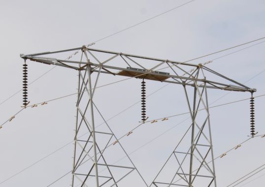
In the case of FortisBC, the first round of insulator testing began in 2016 and involved a 230 kV line equipped with polymeric insulators that were suspected to be nearing their end-of-life after 25-30 years’ service. The line in question runs in a corridor containing two 230 kV lines and a single 138 kV line. Two of these lines are built on double circuit steel structures while the third runs in parallel but has a traditional wooden H-frame construction. The terrain consists mainly of lightly forested hillsides with low insulator contamination.
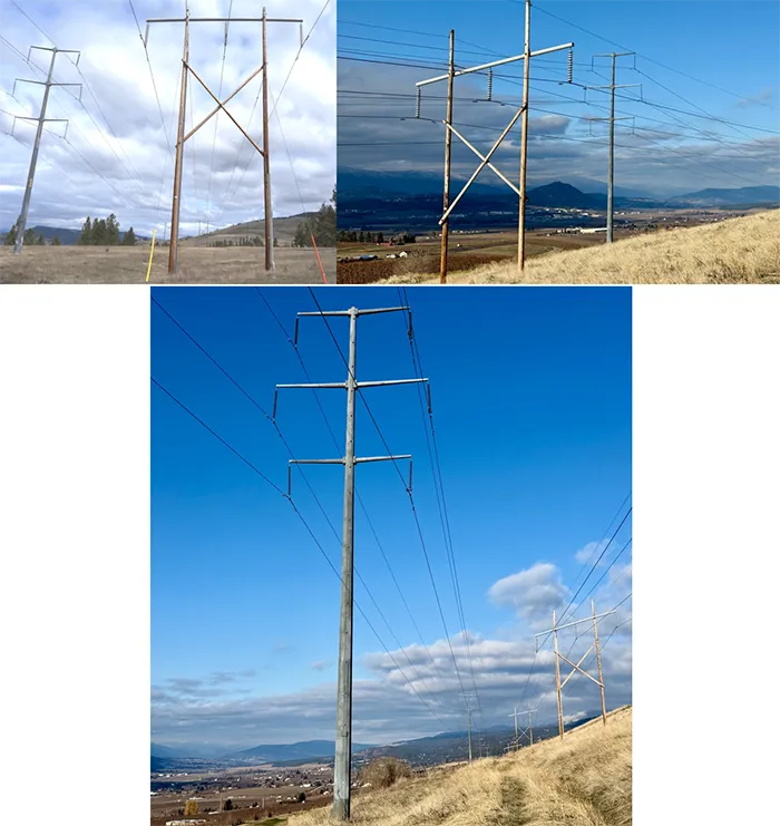
The 230 kV line in question was equipped with two different makes of polymeric insulators installed on tubular steel structures. During routine condition assessment in 2016, these composite insulators were showing signs of degradation although there had not yet been any insulator failures reported. Still, given the criticality of this line and based on the recommendation of a consultant, a small population of these (1 post and 7 suspension insulators from Manufacturer A and 3 suspension insulators from Manufacturer B) were removed and sent to a local high voltage laboratory for testing. These insulators were mid 1980s vintage with about +30 years in-service.
The following tests were conducted:
• Megger test;
• Dry power-frequency voltage flashover;
• ESDD measurement;
• Hydrophobicity;
• Dye penetration;
• Moisture penetration.
These were completed based on relevant standards and guidelines:
• CSA C411.1 – AC Suspension Insulators;
• CSA C411.4 – Composite suspension insulators for overhead lines > 75 kV;
• IEC TS 62073 – Guidance on the measurement of hydrophobicity of insulator surfaces;
• IEC 60060-1 – High-voltage test techniques – Part 1: General terminology and test requirements;
• STRI Guide 92/1 – Hydrophobicity Classification Guide.
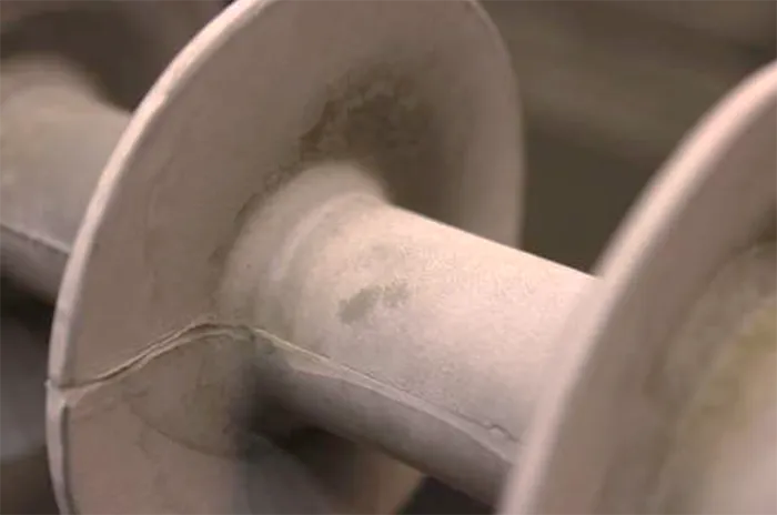
Visual inspection was also completed on all sampled insulators. For Manufacturer A, there were signs of electrical activity, build-up of gray residue and small areas of erosion. These were considered to have failed visually. Insulators from Manufacturer B showed no evidence of degradation and only had small build-ups of dirt. These passed visual inspection.
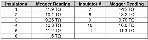
First was the Megger test, which saw 5000V DC applied across the end fittings to yield an overall resistance value. All 11 insulator samples passed with high resistance values, as seen in Table 1.
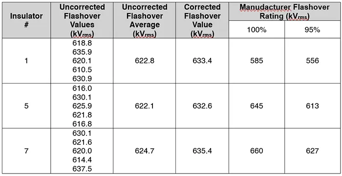
A second electrical test was the dry power-frequency voltage flashover test, which sees a voltage of 75% of flashover rating applied to the insulators and gradually increased until flashover. This process was repeated 5 times for each insulator. All 3 insulators tested this way passed and exceeded 95% of manufacturer ratings (see Table 2).
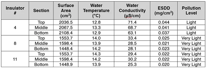
Next came measurement of equivalent salt deposit density (ESDD). Three insulator samples were washed in a 2-litre bucket of de-mineralized water. Due to their length, each insulator was first cut into 3 sections. Resulting water temperature and conductivity were measured and overall ESDD was calculated based on total insulator surface area. According to IEC 60815, ESDD levels were considered light or very light.

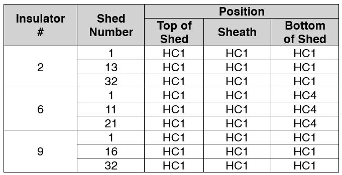
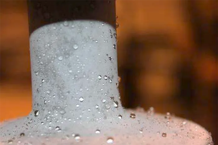
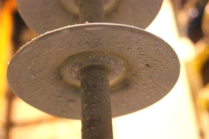
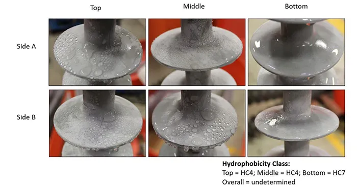
The hydrophobicity test involved spraying water onto insulators for 20 to 30 seconds from 25 cm (±10 cm) away. Hydrophobicity classification (HC) of the tested area was then evaluated based on the STRI Guide 92/1 10 seconds after spraying. The sheath, top and bottom of three insulator sheds on three different insulators were tested. Two insulators had a hydrophobicity rating of HC1 for each shed, while the third had reduced hydrophobicity at the bottom of each shed. Based on their age in service, these levels were deemed acceptable, and all insulators were considered to have passed.

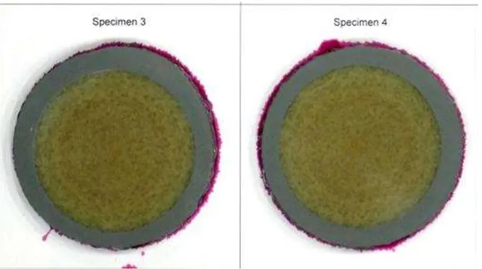
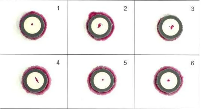
Next came the dye penetration test, which is designed to evaluate the condition of the core material based on penetration of dye through cut samples of each insulator. If the dye penetrates within 15 min of exposure, this is considered a failure. Ten samples were taken from each insulator. All samples of the first insulator tested had no dye penetration over a 15-min time frame. The second insulator, however, had dye penetration within 1 to 3 seconds after exposure for 8 of the 10 cut samples (the remaining 2 had no dye penetration). The final insulator had dye penetration within 8 to 10 seconds after exposure for 1 sample and after 1 minute for a second sample. There was no dye penetration for the remaining 8 cut samples.
Both insulators that had dye penetration were considered to have failed.
Finally, came the moisture penetration test to verify integrity of end fitting seals. This test submerges each of the end fittings in dye for 15 min and then cuts them to determine if any dye has penetrated. Three insulators were tested and all passed.
Based on findings from the first round of testing (2016), it was decided that the polymeric insulators on this 230 kV line were in an acceptable condition to remain in service. Despite a secondary recommendation to repeat testing within a 3-year time window and with an expanded sample of insulators, the second round of tests was slightly delayed.
In 2021, 27 insulators from the same 230 kV line as well as from the adjacent 138 kV line of the same vintage, were removed for laboratory testing. The test program was as in 2016 but this time with addition of a mechanical load test.

Results from the second round of tests showed:
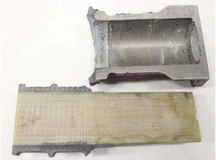
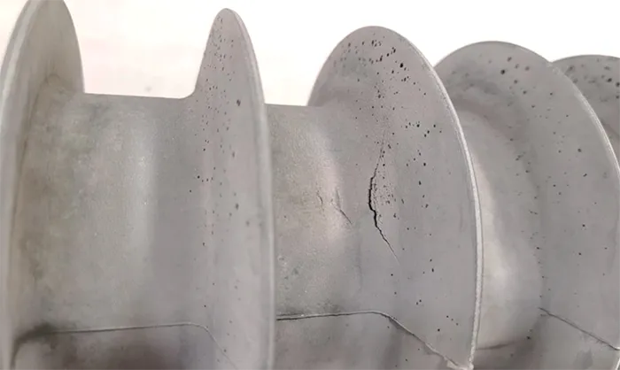
• Further visible damage to insulators, including cracks in the sheath, sheds and metal fittings. Signs of galvanization flacking and corrosion were also identified on metal fittings;
• All insulators passed the Megger test;
• All passed the dry power-frequency voltage flashover test;
• Mechanical load testing was passed, with all insulator samples reaching their routine test load and only 1 of 8 samples not reaching their rated ultimate strength;
• Testing showed decreased hydrophobicity for multiple insulators, with 1 insulator having HC7 on its bottom sheds;
• Only 2 out of 10 insulators passed the dye penetration test.

Conclusions
One of the key questions arising from these types of findings relates to what utilities should do next. From an electrical and mechanical strength perspective, all insulators are still in an acceptable condition. However, due to the failed dye penetration tests in combination with reduced hydrophobicity, it seems clear that these insulators are at risk of accelerated further degradation. Based on the 2 test cycles (2016 & 2021) involving 38 insulators sampled from the total population of 774 on the line, it is still difficult to predict when these may start to fail.
Due to the criticality of the line as well as the age of the insulators, a risked-based decision was made to replace all insulators over the next 3 rehabilitation cycles, as follows:
1. During first cycle in 2025
All dead-end and heavy angle insulators on this critical line will be replaced due to their higher mechanical loads.
2. During second cycle in 2032
All remaining suspension insulators will be replaced.
3. During final cycle in 2040
All polymeric post insulators will be replaced, even though these had passed original testing, since they will already be past their originally expected service-life.
At FortisBC, replacement of in-service transmission insulators follows a condition-based approach which relies mainly on visual inspection, age and records of failure to determine when insulators are nearing end-of-life. At the same time, further testing of batches of these polymeric insulators will be undertaken prior to full line replacement to ensure that they are indeed at end-of-life.