Use of composite insulators has increased among electricity supply companies worldwide due to advantages such as less weight and lower cost, a high mechanical strength-to-weight ratio, high damage tolerance, flexibility, excellent impact resistance and comparative ease of installation. Over time, however, it has also become apparent that insulators of this type are inherently vulnerable to certain types of failure over time. One prominent such failure mechanism has been brittle fracture. These failures have been researched for years and a number of studies established that nitric acid was the principal corrosive medium that formed on composite insulators as a result of corona discharge activity. This acid eventually caused the FRP rod to corrode and fail. The following edited recent contribution to INMR by Daniel Luder, S. Ariely and M. Yal of the Materials Lab at Israel Electric Corp. analysed the costly failure of a composite suspension insulator installed on a 400 kV transmission line along the southern coastline where average relative humidity is about 70%.
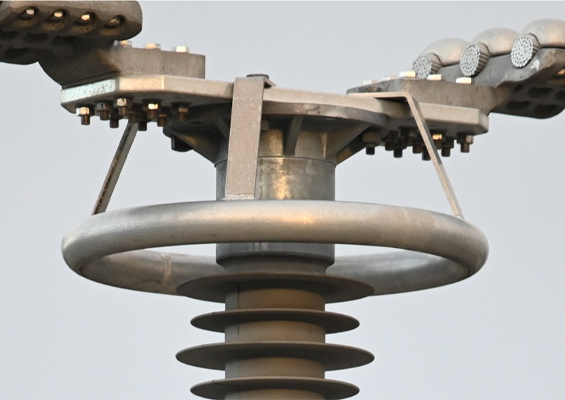
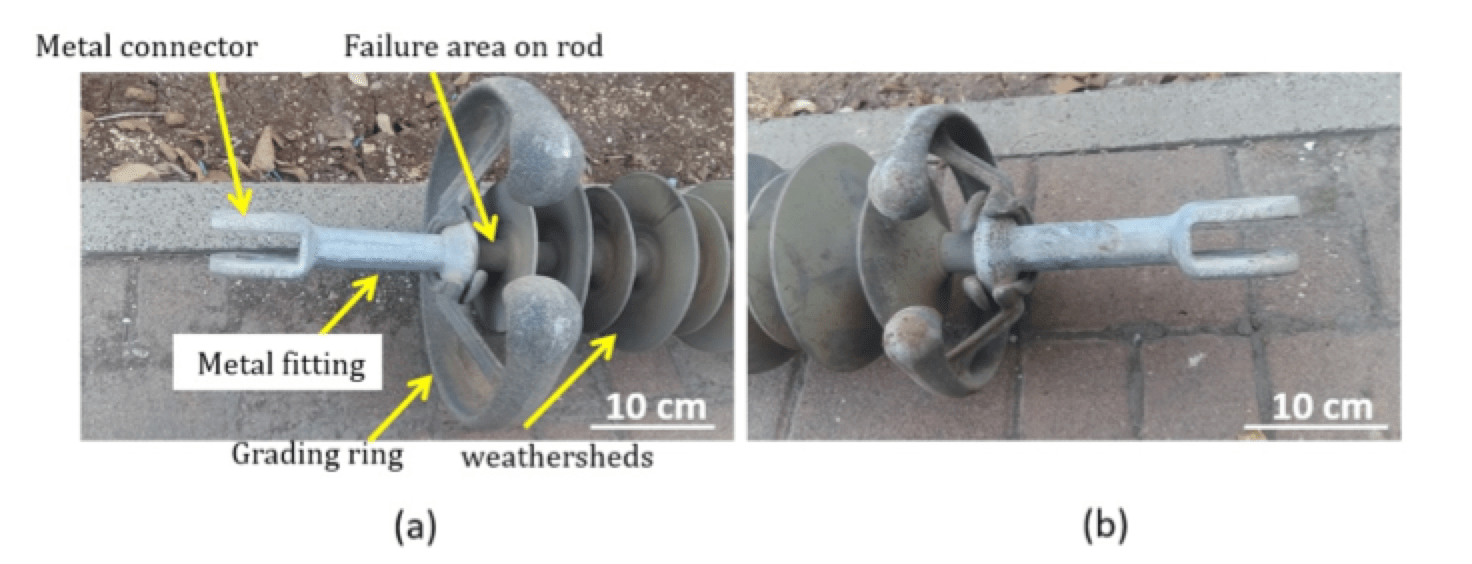
Although the insulator in question had a ‘declared’ life expectancy of 30 years, it failed after 15 years and caused a local outage that, while temporary, came at high cost. An investigation was therefore commissioned to establish the root cause of failure. The 4 m long insulator that failed had 75 weathersheds with alternating diameters of 169 and 137 mm, two grading rings of 210 and 310 mm diameter and metal fittings at either side (see Fig. 1). Its FRP core rod was housed with a protective silicone rubber (SiR) housing that also served as the shed material. Rod diameter, including housing, was 30.3 mm. The metal fittings were attached to the FRP rod using crimping (see Fig. 2).
Initial visual examination of the fracture surface revealed that it had several distinct zones, suggesting a multi-stage failure mechanism involving brittle fracture and fiber pullout. It also revealed that the SiR housing had undergone chemical deterioration at a point just above the area where the FRP had also deteriorated chemically. Stereoscopic examination revealed that the degraded area along the housing included a deep crack along its entire width, from external to internal surface. This enabled passage of pollution from the surface into the FRP rod.

SEM imaging revealed the type of physical damage that had occurred to the FRP material while chemical analysis, via EDS, together with cross-referencing the literature, revealed the nature of the acidic pollutant that had infiltrated the housing and caused corrosion. EDS analysis also estabished presence of nitrogen-based species on the external housing surface as well as chemical deterioration of the housing. This was partly responsible for creating the conditions that enabled crack development along its width. Separately, the chemical content of environmental pollutants on the housing was examined as well. SEM imaging was also used to study the fracture surface of fibers under high magnification. Fractographic evidence then assisted in solidly establishing the insulator’s failure mechanism.
Experimental Methods
Macro images were taken using digital photography and stereoscopic images with a binocular microscope equipped with a digital camera. HR-SEM images and chemical analysis were performed using a Supra-40 microscope equipped with an XPlash EDS detector. SEM imaging and EDS analysis were conducted with an electron acceleration voltage of 5-20 kV and a vacuum of ~10-5 mbar.
The sample for stereoscopic imaging was sawed from the failed insulator and observed without further treatment. Three samples were prepared for SEM imaging. A stage with carbon tape was attached to a small area of the fracture surface in order to collect a sample with fractured fibers. A second sample to view FRP cross-section was prepared by sawing the rod at an area far from the fracture surface. To view the fracture surface of the fibers themselves, the insulator section, including the fracture area, was sawed off approx. 2 cm from the fracture surface. It was then encircled with carbon tape (extended to the SEM stage for electrostatic discharge) and inserted into the SEM vacuum chamber.
To analyze the SiR, a pristine sample was cut from an uncontaminated area on the housing and polluted SiR material was carefully removed from the fracture area. Both samples were stuck to an SEM stage, with carbon tape attached near the area of analysis for electrostatic discharge.

Failure Analysis
Visual Inspection
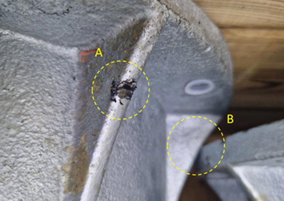
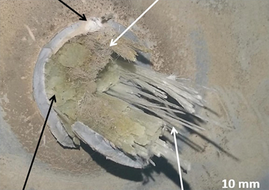
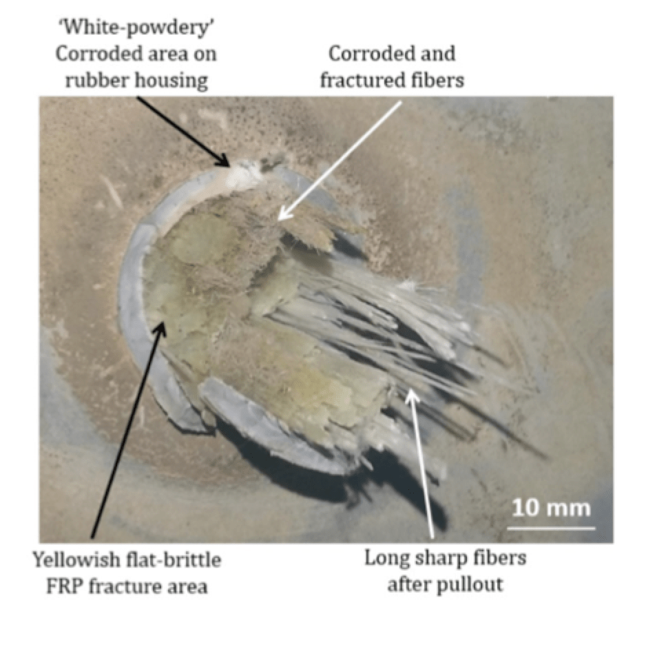
Fig. 3 shows both sides of the insulator fracture. Evidence of severe fiber pullout can be observed at the macro level. It is also evident that the insulator’s exterior is covered with pollutants. At higher magnification, it also becomes possible to notice that neither the fractured housing nor the fracture surface is uniform. In fact, there are three distinct area types at the FRP core (see Fig. 4).
1. An area approximately at the center with corroded and finely fractured fibers having a distinct brown hue;
2. A yellowish (original color of the FRP material) flat fracture that includes both fibers and resin – characterized as an FRP brittle fracture;
3. An area with long sharp fibers that are clearly exposed after pullout from the resin matrix.
Additionally, it can be seen that just above the brown fractured fiber area at the center, the housing has a distinct white powdery appearance surrounded by a limited area with brown hue. This indicates that the rubber housing had itself also corroded since the original SiR housing is solid and grey. Based on this evidence, it can be deduced that a certain chemical process was initiated at the exterior of the rubber housing, causing it to deteriorate and acquire a white powdery appearance. This happened until such point where the process continued into the FRP core just beneath the corroded housing, causing the fibers and resin to corrode as well. The process culminated with final mechanical failure as evidenced by the FRP brittle-fracture area and pullout of fibers. Both of the last mentioned areas maintained their original yellowish hue. Accordingly, it is believed that the process that characterized the fracture of the brown fiber area was both chemical and mechanical in nature whereas the final fracture of the last two yellow areas was purely mechanical.
Stereoscopic Observation
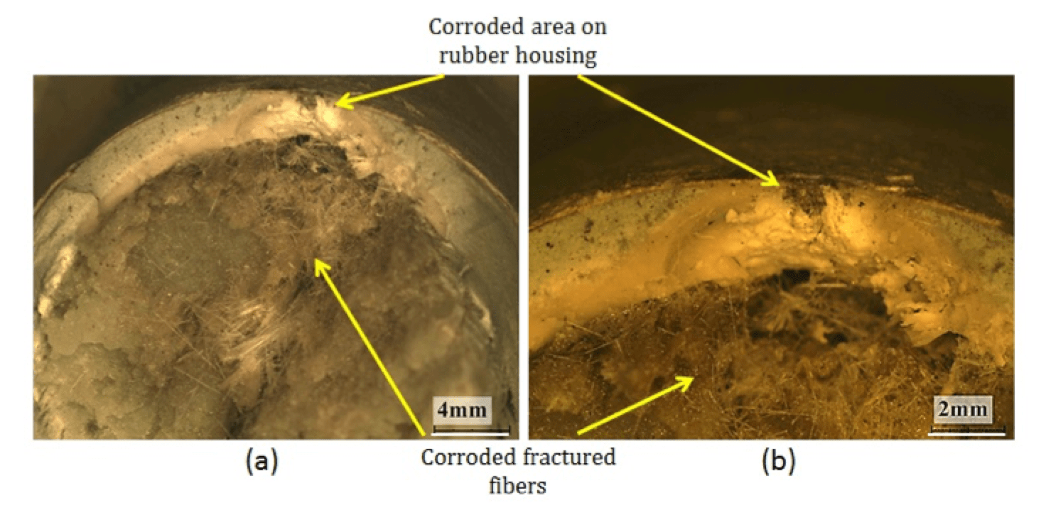
Observation of the fracture’s cross-section reveals that the discolored-corroded area of the SiR housing is located right above the FRP area that includes corroded and fractured fibers (see Fig. 5). It is apparent that this area of the SiR housing has a white powdery appearance instead of being grey and rubbery as in the intact areas. When the corroded area of the housing is viewed under magnification, it becomes possible to observe a transverse crack that crosses the whole width of the SiR housing, from external to internal surface (see Fig. 6). Additionally, the crack had also progressed along the insulator’s axis in the longitudinal direction. It is therefore clear that the FRP rod was easily exposed to any material or pollutant that had reached or formed on the surface. This evidence partially explains the corrosion process that had occurred in the FRP material.
(b) Longitudinal crack on external housing surface;
(c) Longitudinal crack on internal housing surface.
SEM Imaging of Fibers
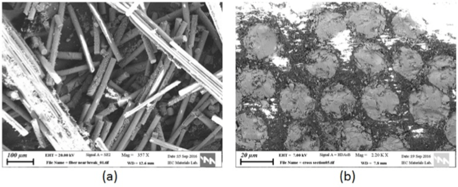
SEM observation of FRP material from the brown corroded area reveals the extent of destruction of fibers (see Fig. 7a). In addition to being fractured into short pieces, these are scattered in random direction and no longer embedded in resin. It is clear that the resin which, according to product data is of the epoxy polymer type, also decomposed with corrosion. Observation of a cross-section of intact FRP material shows that all fibers are oriented in the direction of the rod axis, as expected. Fibers have average diameter of ~20 µm, are boron-free and include materials that comprise alumina-lime silicates (see Table 1), corresponding to fibers of the high-seed ECR type.
Chemical Analysis
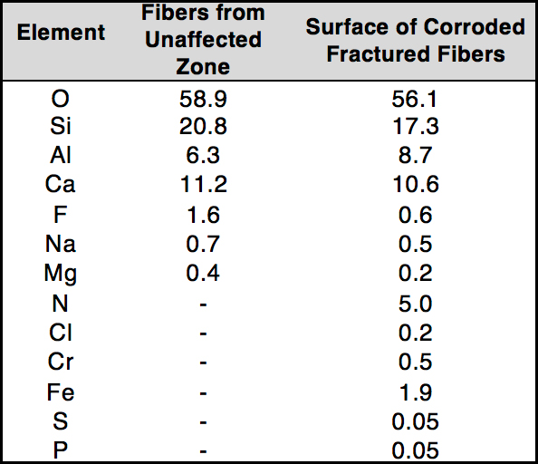
Table 1 presents chemical analysis of unaffected fibers and fractured corroded fibers. A key finding is presence of nitrogen on fractured fibers. During past investigations of similar incidents, it was hypothesized and demonstrated that the main phenomenon responsible for appearance of nitrogen in failed composite insulators was formation of nitric acid on the surface of the external SiR housing. This acid forms as a result of a chemical chain reaction initiated due to presence of humidity (H2O), gaseous nitrogen and oxygen (N2, O2) and corona discharges. It is likely that the origin of the iron (Fe) contaminant is the insulator’s metal connector.
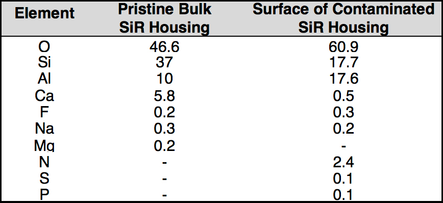
Deterioration in insulation properties and increase in surface conductivity of the insulator cause increasing corona discharge intensity and frequency. Such increase in conductivity is mainly due to accumulated contaminants such as salts, earth materials and other pollutants. Table 2 compares pristine SiR with the contaminated housing surface, after cleaning with a brush. It can be seen that the SiR housing also accumulated nitric acid remnants (as evidenced by the abnormal presence of nitrogen) as well as other pollutants. This was seen together with a decrease in the percentage of elements such as silicon and calcium that are included in the pristine material. It is known that many SiR housing types include alumina tri-hydrate (ATH) and CaCO3 as fillers and that presence of nitric acid causes the formation of Al(NO3)3. Certain quantities of Al and nitrogen in the contaminated SiR, as seen in Table 2, are believed to included in this compound. Additionally, it has been documented that CaCO3 fillers dissolve rapidly in the presence of nitric acid and tend to disappear in an environment with continuous humidity. This phenomenon may have been responsible for the low concentration of Ca found in the contaminated SiR.

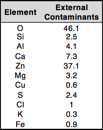
Table 3 presents the chemical content of external pollutant materials collected from the surface. This material includes elements from the housing such as calcium, aluminum and silicon. Additionally, detached material from the insulator’s steel grading ring, such as zinc from the galvanization layer and iron, is also present. Environmental salts such as chloride, potassium, magnesium and sulfur are also present. These pollutants, in the presence of moisture, contribute greatly to the increase in the conductivity of the insulator surface, hence increasing frequency of corona discharges. It has been established that corona discharges can occur at high frequencies near the housing to metal fitting interface due not only to conductivity-enhancing pollution but also to a concentrated electric field at this interface.
Fiber Fractography
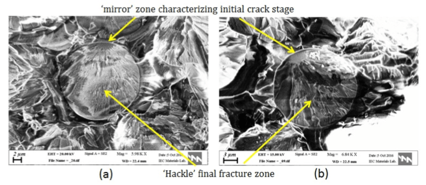
Magnified SEM imaging of the fractured fiber surface reveals a number of notable features (see Fig. 8). At the edge of each fracture surface, a small flat ‘mirror’ zone can be recognized. This zone is characteristic of the initial crack stage that would lead to the final fiber fracture and its size is related to the magnitude of the mechanical stress. At the edges of the ‘mirror’, there is a narrow ‘mist’-like intermediate zone and, finally, a ‘hackle’-textured brittle fracture zone (final fracture). These features are evidence of fracture that occurred by a stress corrosion cracking (SCC) mechanism, as documented in similar reported cases.

Summary & Conclusions
A SiR composite insulator installed in a service area with constant high humidity gradually accumulated environmental contaminants on the housing that protects the FRP core, leading to increased conductivity. In the area of the housing to metal-fitting interface, characterized by abnormally high electric field, this increased frequency and intensity of corona discharges catalyzed formation of nitric acid in a chain reaction involving water, oxygen and nitrogen. The acid and corona discharges altered the chemical and mechanical characteristics of the housing, enabling development of a deep longitudinal and transverse crack. Thereafter, acid migrated into the FRP core where it caused resin decomposition and the development of cracks in the glass fibers in a process involving stress and corrosion. At some critical point, enough resin had decomposed and a sufficiently enough percentage of fibers had fractured that the FRP rod could no longer withstand the stress exerted on the insulator. Critical weakening of the FRP core then caused the insulator to fracture at the corrosion area in a catastrophic and costly failure.
When all the above evidence is considered, the chain of events that led to the insulator’s final failure is explained as follows:
Since the insulator’s installation 15 years prior to failure, it had accumulated a significant amount of pollution such as salts and earth materials from the environment, especially on weathersheds near the lower grading ring. These pollutants, together with the impact of continuous high humidity (~70% ave. RH) and temperature, greatly increased conductivity at the outer surface of the insulator housing. This increase in conductivity and the high electrical field concentration at the bottom of the insulator near the housing to metal-fitting interface, led to increased frequency of corona discharges in this area. In a chemical chain reaction, nitric acid formed as a result of interaction of water with gaseous nitrogen and oxygen, activated by corona discharges. In parallel, there is evidence that a simultaneous process occurred on the housing involving propagation of a wide crack that was both longitudinal and transverse.
Deterioration of the SiR housing involved discoloration to a whitish hue and accumulation of white powdery material. Past research has revealed a process whereby corona discharges and accumulation of nitric acid thoroughly damage SiR housings, dissolving most of the CaCO3 filler and reacting with a large amount of Al to form Al(NO3)3. In addition, during the above process, there is a tendency in SiR containing all types of filler to undergo increased hardness and decreased elasticity while becoming brittle. When added to the impact of long-term exposure to UV, which also increases hardness and lowers elasticity, conditions for development of cracks under moderate loads become apparent. It is also believed that in this case nitric acid migrated not only through the crack but also through voids left over after filler dissolution.
After formation of a path from the discolored housing’s outer surface to the insulator’s FRP rod, acid started to migrate in a straight continuous route into the core. There, the acid facilitated resin decomposition and, in addition, caused corrosion of the glass fibers that contribute greatly to insulator mechanical strength. Corrosion occurred in a simultaneous process involving the existing mechanical load, creating a process of stress corrosion cracking in fibers. After a sufficient amount of fibers had fractured and enough resin had decomposed, the insulator’s FRP core was no longer able to withstand loads due to the line’s weight and movement, leading to failure.
Acknowledgments
The authors thank Mr. Gad Tsafir (IEC) for assisting in operating equipment and fixing malfunctions when needed. Financial assistance of the Vice President for Planning, Development & Technology (Israel Electric Corporation) is acknowledged.
References
[1] D. Luder, T. Hundhausen, E. Kaminsky, Y. Shor, N. Iddan, S. Ariely, M. Yalin, Failure analysis and metallurgical transitions in SS 304L air pipe caused by local overheating, Eng. Fail. Anal. 59 (2016) 292–303.
[2] D. Luder, B. Erenburg, E. Iskevitch, S. Ariely, M. Yalin, Investigation of failure of steel steam generating evaporator tube involving delamination defects and corrosion, Eng. Fail. Anal. 84 (2018) 196-204.
[3] M. Kumosa, L. Kumosa, D. Armentrout, Failure Analyses of Nonceramic Insulators Part 1: Brittle Fracture Characteristics, IEEE Electrical Insulation Magazine, 21(3) (2005), 14-27.
[4] Kumosa, L. S., Kumosa, M. S., & Armentrout, D. L. (2005). Resistance to brittle fracture of glass reinforced polymer composites used in composite (nonceramic) insulators. IEEE transactions on power delivery, 20(4), 2657-2666.
[5] Chughtai, A. R., Smith, D. M., & Kumosa, M. S. (1998). Chemical analysis of a field-failed composite suspension insulator. Composites science and technology, 58(10), 1641-1647.
[6] Albert, R., Albert, I., & Nakarado, G. L. (2004). Structural vulnerability of the North American power grid. Physical review E, 69(2), 025103.
[7] Andersson, G., Donalek, P., Farmer, R., Hatziargyriou, N., Kamwa, I., Kundur, P., … & Schulz, R. (2005). Causes of the 2003 major grid blackouts in North America and Europe, and recommended means to improve system dynamic performance. IEEE transactions on Power Systems, 20(4), 1922-1928.
[8] Chughtai, A. R., Smith, D. M., Kumosa, L. S., & Kumosa, M. (2004). FTIR analysis of non-ceramic composite insulators. IEEE transactions on dielectrics and electrical insulation, 11(4), 585-596.
[9] Ely, T. M. Kumosa (1999) The stress corrosion experiments on an e-glass/epoxy unidirectional composite, journal of composite materials 34 10/2000
[10] Kumosa, M. (2005). Brittle fracture failure of composite (nonceramic) insulators. IEEE Trans. Power Delivery.
[11] Y. Koshino, I. Umeda and M. Ishiwari, “Deterioration of silicone rubber for polymer insulators by corona discharge and effect of fillers,” 1998 Annual Report Conference on Electrical Insulation and Dielectric Phenomena (Cat. No.98CH36257), Atlanta, GA, USA, 1998, pp. 72-79 vol. 1.
[12] Grasaesom, J., Thong-Om, S., Payakcho, W., & Marungsri, B. (2011). Ageing deterioration of silicone rubber polymer insulator under salt water dip wheel test. Journal of World Academy of Science, Engineering and Technology, 56, 211-217.
[13] B. Marungsri, H. Komiya, H. shinokubo, R. Matsuoka, S. Kumagai, Effect of salt fog conditions on deterioration of housing materials for polymer insulators in salt fog ageing test (2005)
[14] D. Hull, M. Kumosa, J. N. Price, “Stress Corrosion of Aligned Glass Fiber-Polyester Composite Material,” Materials Science and Technology, Vol. 1, pp. 177–182, 1985.
[15] Chun Fang Yi, Qian Shi, Pei Song Liang, Effect of UV Radiation on HTV-Silicon Rubber under Different Humidity, Advanced Materials Research (2014) 986-987.