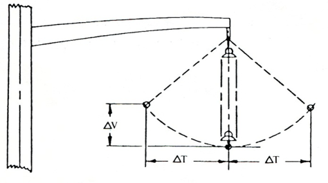
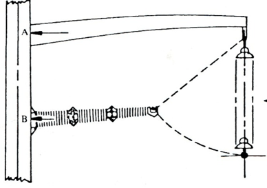
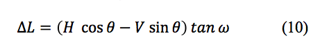
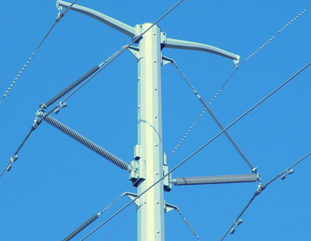
Braced insulator assemblies are a type of armless construction for transmission line designs introduced when the first horizontal line posts were installed many years ago. Minimum clearances for conventional line construction, such as using a vertical suspension string, require an allowance for displacement of the string due to transverse winds and line angles (as in Fig 1). Replacing the vertical string with a horizontal line post type insulator (Fig. 2) fixes the conductor attachment point and allows for both reduced right-of-way widths and lower support structures. The challenge, however, has been that line post insulators typically have lower load carrying capacity than suspension insulators. In some cases this limits span lengths and conductor size.
CLICK TO ENLARGE
CLICK TO ENLARGE
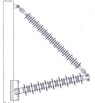
An improvement in load carrying capacity can be achieved by adding a brace attached to the line end of the post and attached to the support structure at an appropriate angle (as in Fig. 3). Many of the advantages of the single-post insulator are retained with this type of insulator assembly, while increasing load carrying capacity
CLICK TO ENLARGE
For example, a typical 138 kV line supported with a vertical 120 kN specified mechanical load (SML) polymeric suspension insulator has about 8 times the load carrying capacity of the line than if it was supported with a polymeric line post having a 63.5 mm diameter fiberglass rod. Adding a suspension brace with a 60° angle between brace and post members, increases the assembly’s load capacity by 87% versus that of the vertical suspension insulator. Fixing the position of the conductor also retains the benefit of reduced right-of-way requirement.
This edited past contribution to INMR by Anthony Baker (now retired) of K-Line Insulators reviewed strength requirements of braced line post configurations.
Types of Braced Insulator Assemblies
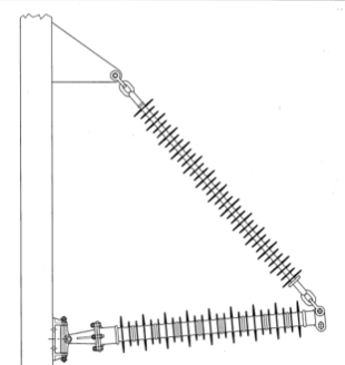
There are two types of braced insulator assemblies, depending on how the post member is attached to the support structure: if the post member attachment point is rigidly fixed (as in Fig. 3), the assembly is referred to as a Braced Post; alternatively, if the post member attachment point is designed to allow it to rotate about an inclined axis provided by a stub arm attachment point for the brace member (as in Fig. 4), the assembly is referred to as a Pivoting Braced Post – or, more commonly, a Horizontal Vee.
CLICK TO ENLARGE
Early braced insulator assemblies were horizontal vee assemblies consisting of a porcelain suspension insulator string brace and a slender porcelain strut, as the post member. By providing a pinned-end connection of the strut to the structure, unbalanced longitudinal loads at the line-end of the assembly results in rotation of the assembly and not in bending loads in the porcelain strut. The slender struts (typically 82.5 mm diameter) were rated only in tension and compression (cantilever strength rating = 0). Dynamic longitudinal loading could result in cascade type failure of lines supported on porcelain line post insulators. As such, braced post type assemblies were not really feasible until the advent of polymeric line post insulators over 25 years ago. As discussed later, the mechanical stability of horizontal vee lines under high wind conditions is a severe operating constraint and most braced insulator assemblies installed today are therefore of the braced post type.

Load Analysis
A braced insulator assembly subjected to a horizontal (wind & line angle) load H, vertical (weight) load V, and longitudinal (e.g., unequal ice or tensions in adjoining spans) loads L1 and L2 is sketched in Fig. 5.
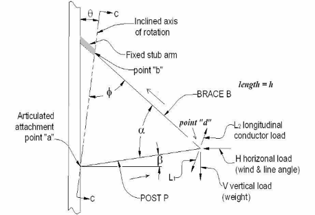
or articulated (horizontal vee). An inclined axis of rotation for assembly (angle ) is required for horizontal vee.
CLICK TO ENLARGE
For the condition of balanced longitudinal loads (L1=L2), the load P in the post member and load β in the brace member of the assembly, with an included angle and a post angle as shown in Fig. 5 can be expressed as:
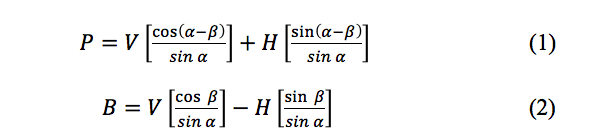
or
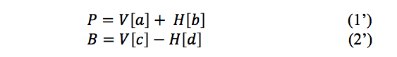
Brace and post member loads must be limited to be no more than the maximum allowed working loads for either member. If Bmax and Pmax are the maximum allowed working loads of the brace and post respectively, then for a given horizontal load H, the maximum allowed vertical load V is the smaller of
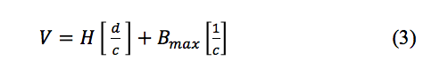
or
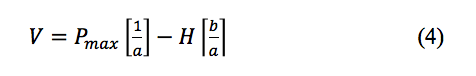
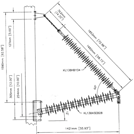
Maximum allowed vertical loads as a function of the applied horizontal load, due to wind only, for a 60° included angle braced post assembly with a 120 kN SML rated polymeric suspension brace (Bmax=60 kN) and a polymeric post rated in tension or compression at 66.7 kN (Pmax=33.3 kN) shown in Fig. 6 are given in Fig. 7.
CLICK TO ENLARGE
Horizontal loads in a direction away from the support structure (here taken to be the negative direction) tend to load both the brace and the post in tension and would appear to increase the vertical load limit, while those toward the structure reduce it. However, the increased vertical load capacity for loads directed away from the pole cannot be realized in service since the limit increases as the wind speed increases.

CLICK TO ENLARGE
The brace component, being a suspension type insulator (polymer or ceramic) is not designed to be loaded in compression, and a minimum vertical load, which is also a function of the total horizontal applied load, is required as shown in Fig. 7. Setting B ≥ 0 (2) shows that the minimum vertical load required is equal to or greater than H (tan ). This is not usually a major concern, but must be considered for each application, in particular those for which high speed winds may be encountered. For lines supported on braced insulator assemblies, the effects of a difference in the longitudinal loads L1 and L2 at the conductor attachment (“point d” in Fig. 5) depends on the type of assembly employed.

Longitudinal Loads
Braced Post Assemblies
An unbalanced longitudinal load (L≠0) in combination with vertical (V) and horizontal (H) (toward the support structure) loads can result in a bending moment applied to the post member of a braced post insulator assembly due to its rigid attachment to the support structure (“point a” in Fig. 5). For a single polymer line post (i.e. without the brace), the line-end deflection (δ) of the post subjected to these loads would be:
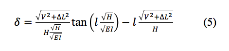
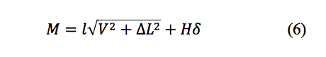
where l is the length and EI is the flexural rigidity of the post. The total bending moment as a result of the applied loads for a single post is:
and so the requirement for a given polymer post is that:
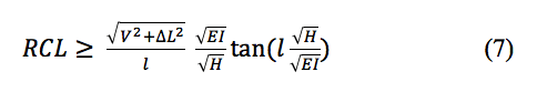
where RCL is the rated routine cantilever load (50% of the specified cantilever load or SCL) of the post. Braced post assembly vertical loads are carried by a tension load in the brace and tension or compression load in the post as shown in (1) and (2), and any unbalanced longitudinal load, as a result of different conductor tensions in adjoining spans, will be resisted by a both a bending moment in the post and a component of the brace load along the line. If the along-line brace component is designated BL, and if a post insulator satisfying (7) is used as the post member of a braced post assembly, then for V=0 (7) becomes:
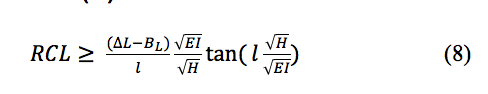
A given braced post is then suitable for an application as long as the unbalanced longitudinal loads satisfy the condition that:
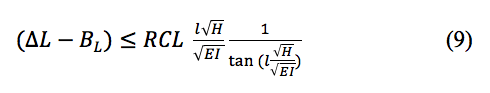
The braced post assembly shown in Fig. 6 has a post member with an RCL rating of 7.5 kN and, not considering the brace load component (BL) resisting any longitudinal displacement load, (9) indicates that the assembly can support up to about 80% of the RCL even when subjected to a 29 kN horizontal load.
Horizontal Vee Assemblies
If “point a” of Fig. 5 is an articulated attachment as shown in Fig. 4, there will be no bending moments in the post member of a braced assembly because the assembly will rotate about its inclined axis in response to any unbalanced longitudinal loads. As noted earlier, the first braced assemblies were porcelain horizontal vees with slender struts not rated in bending. A horizontal vee with an inclined angle and subjected to a longitudinal load L=T will rotate about its axis through an angle and its line end (“point d” in Fig. 5) will be displaced in the unbalanced direction by an amount D as depicted in Fig. 8 where l is the perpendicular distance between “d” and the inclined axis of rotation.
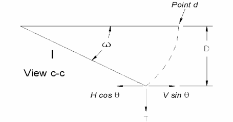
about inclined axis by unbalanced longitudinal load.
CLICK TO ENLARGE
The component of T along l is T cos and the components of the vertical and horizontal loads along this line are shown in Fig. 8 which leads to:
When V sin is greater than H cos the angular displacement of the assembly is limited by the weight component which tends to return it to its un-rotated state. However, if this condition is not met. assembly rotation is limited only by the applied load and the lengths of its brace and post members.
Horizontal Vee Stability
A line supported on horizontal vee assemblies and subjected to a sufficiently high transverse wind load can have some of its assemblies rotated and, as a result, sag will be pulled out of one span and added to the adjacent one (as in Fig. 9). These adjoining span sag changes, along with the effect of an inclined axis of rotation for the insulator assemblies, results in differential conductor tensions at the assembly attachment point which tends to counteract the initial displacing force and maintain mechanical stability of the line.
as result of unbalanced longitudinal loads.
CLICK TO ENLARGE
If however, the number of adjacent spans between points of longitudinal restraint such as at dead-end structures is large enough, the accumulated displacements at each conductor support point can result in a type of line cascade failure as shown in Fig. 10. Mechanical stability of a horizontal vee the line with respect to high transverse wind loads increases as:
• assembly and conductor weight increases
• assembly inclined axis of rotation increases
• conductor tension increases
• the number of spans between points of longitudinal restraint (e.g. dead-ends) decreases
Increasing line tension may be realistically considered in the early design stage but if line stability problems emerge after construction, it usually is not. Likewise assembly design features such as the inclined angle can be easily changed in design but would be a difficult retrofit.
CLICK TO ENLARGE
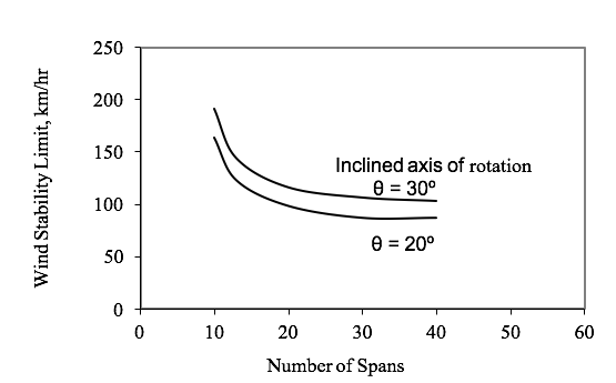
The relative improvement in the stability limit of a horizontal vee line subjected to high transverse winds (the wind stability limit) is demonstrated in Fig. 11 where the limit is given as both a function of decreasing the number of spans between points of longitudinal restraint and increasing the assembly included angle from 20° to 30° for a twin bundle conductor 345 kV line with 244 m spans.
CLICK TO ENLARGE
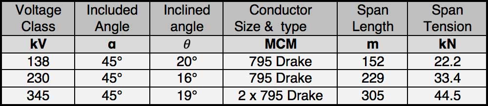
Increasing the inclined angle of this assembly and reducing the number of spans between points of longitudinal restraint increases the limit, but for the latter the improvement becomes dramatic when the number of spans is reduced below 15. Wind stability limits for a proposed horizontal vee line should be considered, in particular if design load requirements do not ensure that V > H cot under all conditions. There are several ways to increase the wind stability limit in the design stage, but few after the line is built and then found to have an unsatisfactory limit. Reducing the number of spans between points of longitudinal restraint can be a good method because, though usual longitudinal restraint points are typical dead-end structures, here only enough strength to resist differential longitudinal loads imposed by a transverse wind is required. The effectiveness of reducing the number of spans between longitudinal points of restraint for three different lines described in Table 1 is shown in Fig. 12.
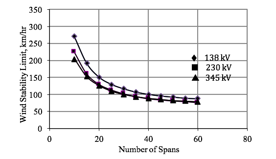
points of longitudinal restraint for lines described in Table 1.
CLICK TO ENLARGE
The stable wind limit increases dramatically as the number of spans are reduced to 15 or less between points of longitudinal restraint for all three lines considered. Most of the time, a wind stability limit of about 150 km/hr will exist for a proposed horizontal vee line if the number of span subsections is limited to 10 or less spans.

Longitudinal Restraint Assemblies
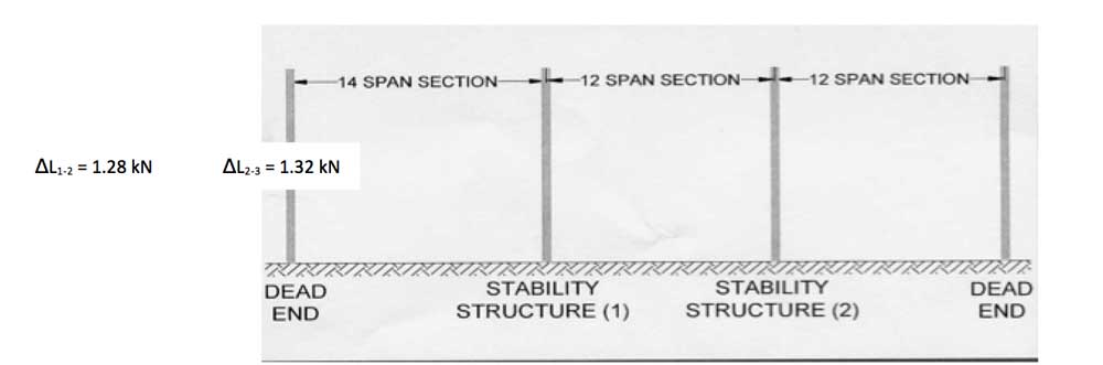
Subdividing conventional dead-end-to-dead-end sections of a horizontal vee line into subsections with longitudinal restraints points can be accomplished by replacing some of the horizontal vee assemblies along the line with non-rotating types of insulator assemblies such as braced post assemblies or insulated cross-arm types of assemblies. The lower strength required for longitudinal restraint assemblies for sectionalizing a horizontal vee line compared to full strength dead-ends can be demonstrated by considering the example of a 38-span 230 kV line with a 1315.5 MCM ACSR conductor with an ultimate strength rating of 212 kN, and spans lengths varying from 149 m to 271 m. The wind stability limit for this line was increased from 121 km/hr for the 38-span section to 177 km/hr by sectionalizing the line into one 14-span and two 12-span subsections as depicted in Fig. 13. As shown the conductor differential tension at the sectionalizing points is 1.32 kN or less. Replacing some horizontal vee insulator assemblies in a line with composite insulator braced post assemblies is a very cost effective way of improving the wind stability limit of a horizontal vee line because support structure modifications are simple.
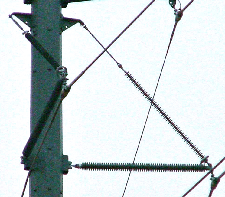
The double circuit 230 kV shown in Fig. 10 was stabilized by converting every fourth structure in the line to a braced insulator assembly shown in Fig. 14.
for every 4th structure on 230 kV line to improve wind stability.
CLICK TO ENLARGE
Post Member Buckling
Transverse loads can result in a compression load in the post member of a braced insulator assembly, as in Fig. 5, or a tensile load if the transverse wind and/or line angle load is in the opposite direction. Since the post member has a long column structure, its resistance to buckling under compression loading must be considered. Euler’s column formulations show that end attachment details for the post member has a large effect on buckling resistance. A braced post assembly has a post member with a pinned line end and a fixed base, while for a horizontal vee assembly both ends of the post member are pinned. As per Table 2, for strictly axial loads the critical buckling load would be twice as great for a braced post assembly as for a comparable horizontal vee assembly if the column end conditions were perfectly rigid or pinned.

CLICK TO ENLARGE
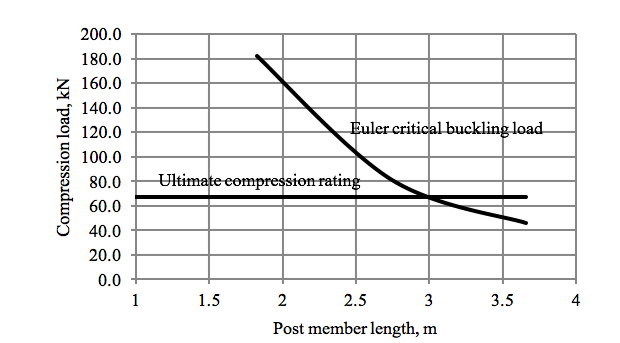
As shown in Fig. 6, a typical line end fitting for the post member is a drop-tongue configuration so that the brace component and conductor attachments may result in a net eccentric compression loading of the post member. Also for a braced post assembly, the post base is itself an assembly of parts and not completely rigid. Actual buckling loads for the post member may be less than the Euler column formulations would predict. The Euler buckling load for a 63.5 mm diameter fiberglass rod polymer post in a braced post assembly is greater than its rated ultimate compression strength until the post length is about 3 m long as shown in Fig. 15. Typical applications for this size rod post are at 2.5 m or less providing a comfortable margin with regard to buckling loads, but each application requires careful consideration.
CLICK TO ENLARGE
Conclusions
Bracing the line end of a horizontal line post insulator with an appropriately attached suspension insulator increases its load carrying capacity while maintaining many of the benefits of the single-post configuration. Braced insulator assemblies can have a support structure attachment of the post member with a fixed or a pivoting base. The fixed base configuration is a Braced Post Assembly and the pivoting base configuration is a Horizontal Vee Assembly. Early braced insulator assemblies were porcelain horizontal vees because a pivoting post base was required to avoid dynamic bending loads in the post member. Mechanical stability with respect to transverse wind loads is a serious concern for lines supported on horizontal vee insulator assemblies. Cascade type failures have occurred on improperly designed lines.

Braced post insulator assemblies became feasible with the introduction of polymeric insulators. Lines supported on braced posts are not subject to the mechanical instability concerns associated with horizontal vee lines. If horizontal vee lines are designed with line sections between points of longitudinal restraint consisting of 10 spans or less, wind stability limits of 150 km/hr can be expected but each case should be considered in detail. Normal longitudinal restraint points for transmission lines are dead-end structures, but such strengths are not required when subdividing horizontal vee lines into span subsections to improve system stability with respect to high transverse winds. In general, buckling is a not a major concern for braced insulator assemblies with a 63.5 mm diameter fiberglass rod polymeric post member 3 m or shorter so long as the applied loads are below the maximum allowed tension/compression working load of the post.