Shielding electrodes are usually specified for AC lines to eliminate corona from insulator fittings, to grade the voltage potential along the string and limit radio interference from insulators as well as the effect of power arcs. In particular, grading electrodes are essential in AC to mitigate voltage drops/electric field on insulators, especially on the line side. Grading electrodes significantly reduce the stress and limit radio interference for cap & pin insulator strings. This role becomes even more important for composite insulators to avoid localized critical electric field strength that may cause premature ageing. The situation is different in DC where voltage distribution is generally dominated by resistive currents, both under clean and contaminated conditions. However, design of shielding electrodes for DC line insulators in recent projects has still been similar to what is usually adopted in AC. This edited contribution to INMR by insulation expert, Alberto Pigini, reviews different shielding requirements for both AC and DC lines and presents results of past investigations conducted on cap & pin insulator strings. The case for composite insulators is also analysed by ad hoc electric field calculations performed under AC and DC voltage.

Laboratory Experience with Cap & Pin Insulators
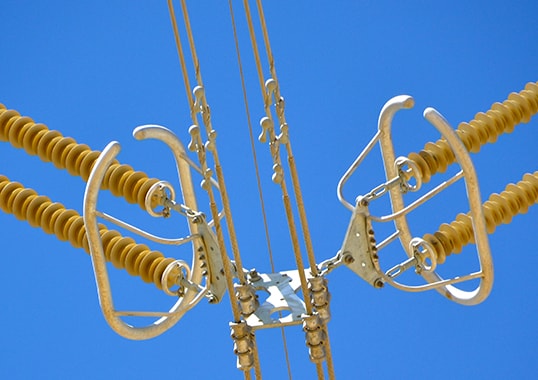
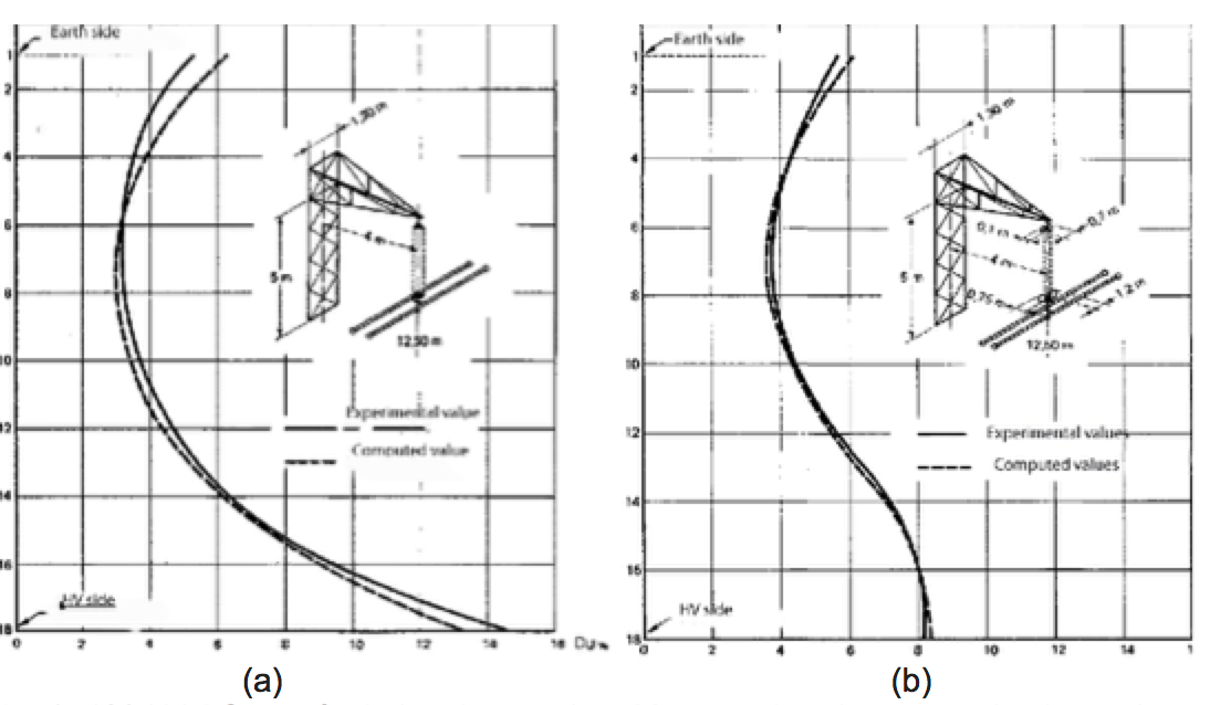
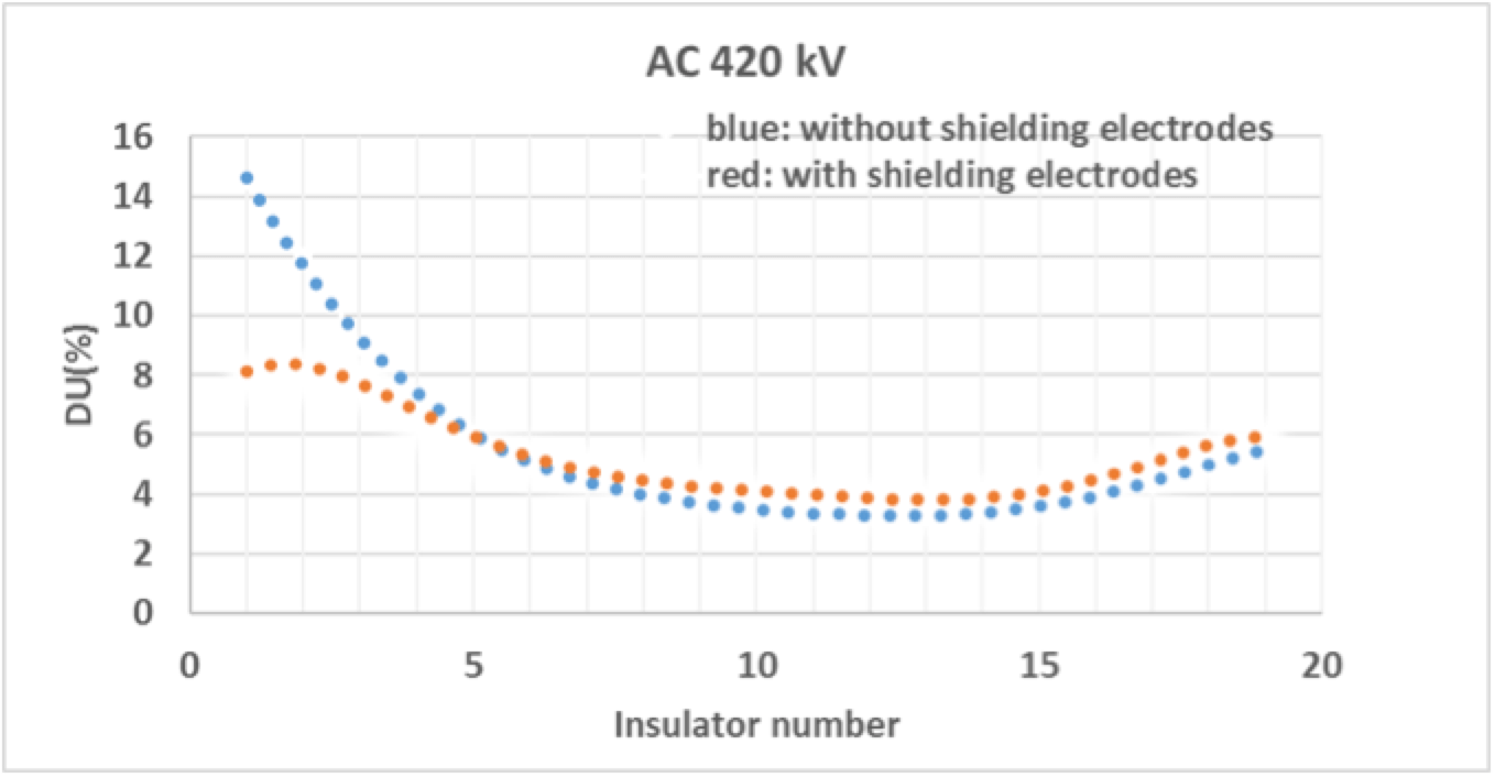
Grading electrodes are essential in AC to mitigate voltage drop/electric field along insulators, especially on the line side. Fig. 1, for example, reports voltage drop, in p.u., measured across each cap & pin disc for a 19 unit 420 kV insulator string – with and without shielding electrodes.
CLICK TO ENLARGE
The trend can be reproduced by electrostatic field calculations, taking into account insulation geometry and permittivity of the different materials. While evaluated under clean conditions, the voltage distribution can also be assumed valid under contaminated conditions whenever capacitive currents prevail over conductive currents. Fig. 2 provides a direct comparison between measured voltage drops, with and without shielding electrodes.
CLICK TO ENLARGE
It is immediately evident that, without grading electrodes, the voltage drop on the first unit of the string can be high, e.g. up to three times the average. Grading electrodes significantly reduce this stress and are therefore important to limit radio interference for cap & pin insulator strings under AC voltage. Indications for shielding design to comply with corona and radio interference design with special reference to UHV AC have already been published.
The situation, however, is different in DC where voltage distribution is dominated by resistive currents – both under clean and contaminated service conditions. Non-uniform distributions, similar to those in AC, can be obtained for new cap & pin insulators, cleaned thoroughly under conditions of low humidity. Conductance values of 10-13 S with currents on the order of magnitude of nA have been recorded on new insulators cleaned using ultrasound. Conductance values of 10-12 to 10-11 S have been recorded on new insulators cleaned carefully with alcohol, with surface currents of some tens of nA.
On the other hand, if an insulator string and fittings are well designed from the corona point of view, the configuration can be considered ‘corona free’. In this case, the ion current in air is limited, i.e. on the order of only a few nA. Under ideal laboratory conditions, with new and extremely clean insulators, ion currents in air can have influence voltage distribution, being on the same order of magnitude as surface current. This makes voltage distribution close to that in AC, i.e. dominated by capacitances.
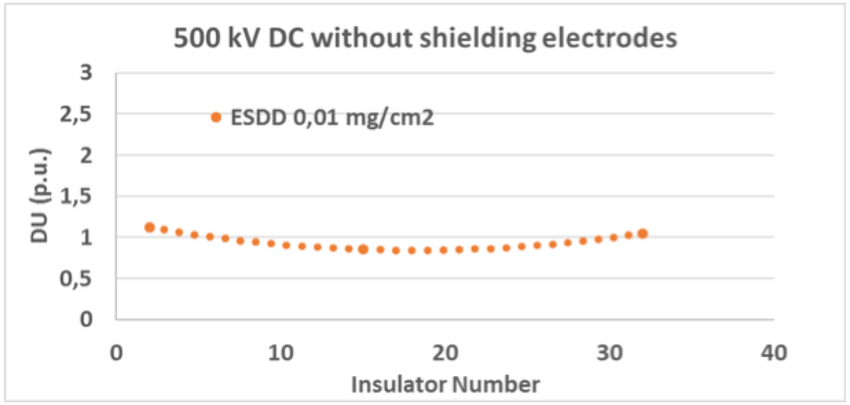
Under practical field conditions, however, surface conductance can easily exceed 10-9 S for weathered or very lightly polluted insulators. Surface currents are then on the order of hundreds of nA or higher, thereby making the effect of ion currents in air negligible and with a tendency toward a linear voltage distribution. Fig. 3 shows an example of voltage distribution measured on a 32 unit cap & pin insulator string for 500 kV DC, without grading electrodes. The string was uniformly contaminated with low pollution (ESDD=0.01 mg/cm2) and exposed to a normal environment with humidity below 76%.
CLICK TO ENLARGE
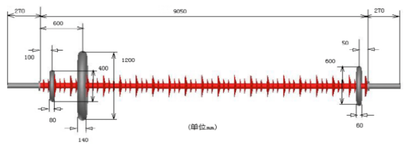
The voltage on the first insulator in the string is only marginally higher than the average. Therefore, measurements indicate that additional field grading by shielding electrodes is not necessary. The above considerations hold in the simplified case of a nearly uniform conductivity condition along the entire string, in the absence of corona phenomena. In practice, however, non-uniform contamination can occur, with greater pollution accumulation at the high voltage side due to the influence of electric field in DC. This was confirmed by tests performed in a dust chamber on an I-string of 7 cap & pin insulators (see Fig. 4) and can further contribute to reducing voltage non-uniformity along the string.

CLICK TO ENLARGE
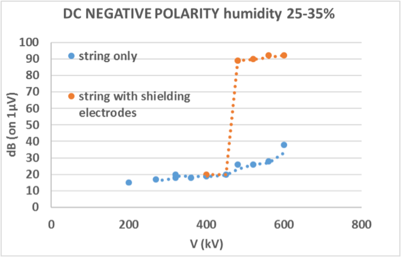
Confirmation of the negligible impact of shielding electrodes in DC was given by radio interference RIV measurements performed on a 21-unit insulator string with and without shielding electrodes (see Fig. 5). Results confirm that influence of shielding electrodes is negligible up to about 450 kV and then actually becomes detrimental once corona starts from the shielding electrodes themselves.
CLICK TO ENLARGE
However, shielding electrodes of limited size, different from those typically adopted in AC, may be necessary to prevent corona from insulator fittings. Beyond giving rise to unacceptable RIV, this can also contribute to enhance the pollution. Fig. 6 refers to tests in a dust chamber, with corona generated by a 15 cm long sharp needle projecting from the conductor, close to the line end insulator.

CLICK TO ENLARGE
Composite Insulators
Simplified Representation for Electric Field Calculation
As an example, reference is made to composite insulators for UHV applications and Fig. 8 shows design of suspension insulators adopted for the 1000 kV AC system in China.
CLICK TO ENLARGE
Similar shielding configurations were adopted for ±800 kV DC lines, as shown in Fig. 9.
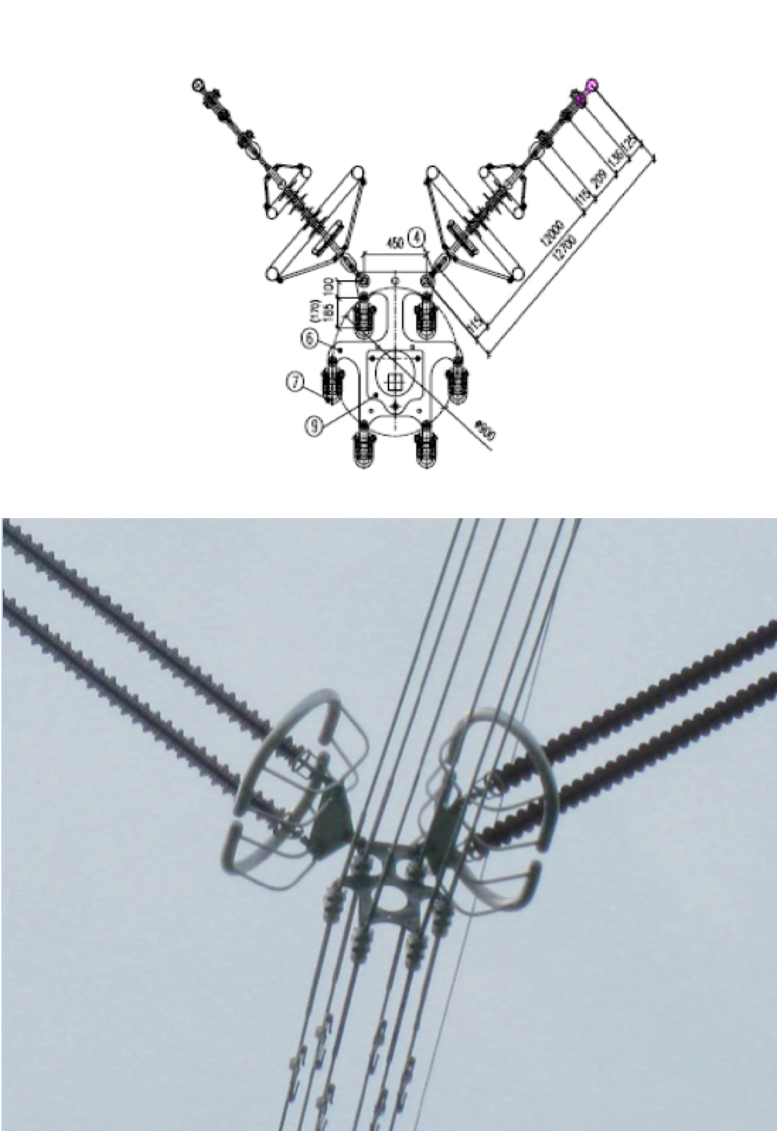
CLICK TO ENLARGE
Since the purpose of these calculations is to put into evidence the different role of grading rings in AC and DC, a simplified schematization of the composite insulators is made. Total insulator lengths and size of the shielding electrodes were taken, as in Fig. 8, both for AC and DC. The composite insulator is represented by a rod, without sheds, with a 90 mm diameter of homogeneous material having a dielectric constant, ɛ, of 3 and a conductivity, σ, of 10-13 S/m. For the surrounding air, with ɛ of 1 and conductivity σ of 10-14 S/m were assumed in the simplified case of absence of significant ionization by corona. Surface conductance was simulated assuming a pollution layer of 1 mm having the same conductivity all along the insulator. Different conductivities of the pollution layer were considered as representing clean laboratory conditions (i.e. the ideal case), weathered and lightly polluted insulators that had lost part of their initial hydrophobicity. Voltage distribution was evaluated by ANSOFT under AC and DC at the same voltage of 800 kV. To obtain an indication of field gradient along the surface, reference was made to the voltage derivative along the surface.

Results
Calculation results are reported in Figs. 10, 11 and 12, which compare the voltage distribution and its derivative in AC and DC, with and without shielding electrodes. The following cases were simulated for the composite insulator in Fig. 8, suitably schematized:
• Application of DC voltage without rings;
• Application of AC voltage without rings;
• Application of DC voltage with rings;
• Application of AC voltage with rings.
CLICK TO ENLARGE
In the ideal case, with a conductivity in the surface layer equal to the assumed conductivity of the insulator simulation (10-13 S/m), voltage distributions under AC and DC voltages are superimposed and similar to those evaluated for the same insulator. Surface current is very low, on the order of magnitude of 10-12 A, and voltage distribution under DC is practically identical to that under typical ‘capacitive’ AC. Moreover, influence of shielding electrodes is the same.

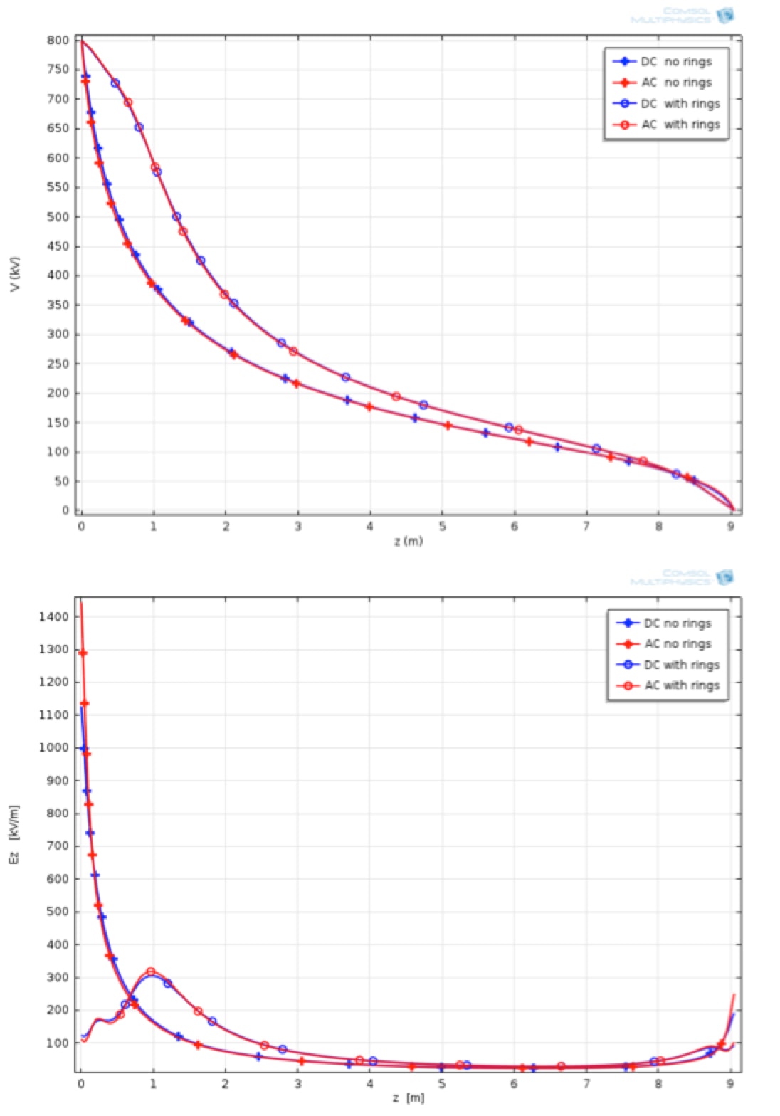
But the situation changes rapidly when considering surface conductivities more representative of weathered and lightly polluted conditions. Assuming a conductivity in the layer of 10-10 S/m, surface currents with order of magnitude of 10-9 are obtained. These are already sufficient to differentiate the distribution in DC from that in AC, as shown in Fig.11.

CLICK TO ENLARGE
Already, with conductivity in the layer of 10-7 S/m and surface current along the layer of 0.02 μA, the surface current dominates the voltage distribution. In the assumed case of uniform conductivity in the layer, this leads to a linear voltage distribution for DC, while the voltage distribution in AC remains dominated by capacitive parameters, as shown in Fig. 12. While shielding electrodes continue to control the distribution in AC, they are not influential in DC. Even if the case of uniform conductivity along the layer is simplified, calculations still indicate that, for DC, voltage distribution in the presence of weathered insulators can be considered to be controlled by resistive parameters on the surface, with no influence by the shielding electrode.
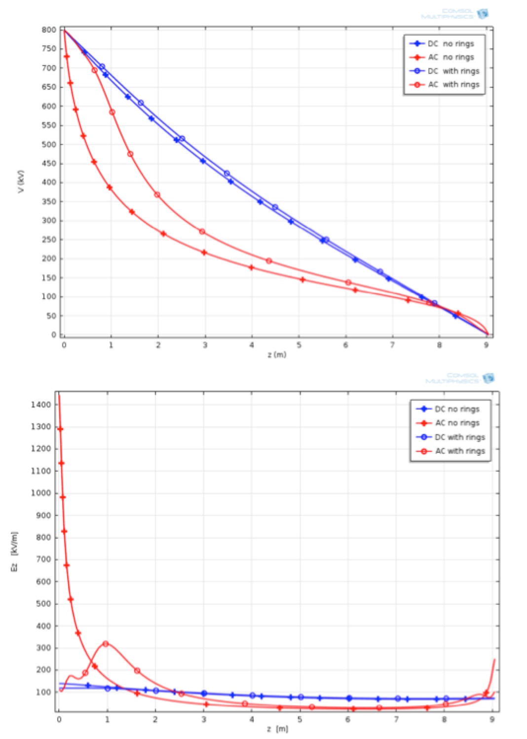
CLICK TO ENLARGE
Analysis
Behaviour of insulators under clean, ideal conditions is similar in AC and DC and shielding electrodes have basically the same role in terms of mitigating electric field. However, as soon as insulators become ‘weathered’, with surface leakage current on the order of magnitude of 1 μA, distribution of potential for DC is dominated by surface conductance. As a result, in the case of AC shielding electrodes, these have significant influence on electric field and may even be mandatory for composite insulators to avoid the possibility of premature ageing due to both dry and water-induced corona (i.e. max. allowable E-field of 0.42 kV/mm for more than 10 mm along the insulator surface and not exceeding 0.35 kV/mm on the end fitting seal have been recommended).

By contrast, under practical conditions, influence of shielding electrodes becomes negligible in DC. Shielding electrodes of reduced size may still be useful in DC if there is a need to shield sharp metallic points on the fittings to avoid corona. But they may not be useful to control electric field along the insulator, as necessary for AC applications. An additional consequence is that corona and RIV tests on DC insulators, with the insulator new and performed under ideal clean conditions, may not be representative of actual service conditions.
Actual insulator conditions may prove more complex than what has been assumed in the above. As example, charges can accumulate in the space and along the insulators as a consequence of ionization phenomena or conductivity along the surface might not be uniform due to different levels of contamination, e.g. higher accumulation on the live side. However, in all cases surface condition will continue to dominate voltage distribution, making negligible the capacitive influence due to the shielding electrodes.
Conclusions
Shielding electrodes of different type are usually foreseen and prescribed for AC lines to:
A. eliminate corona from insulator fittings (i.e. a corona shielding function);
B. grade the voltage potential along the string in order to limit radio interference from insulators and, for composite insulators, to reduce ageing phenomena (i.e. a grading function);
C. limit the effect of power arcs (i.e. a protective function).
For DC applications, possibly smaller and specific shielding electrodes may be necessary to cover function A. But these are useless, in practice, to cover function B since, for weathered insulators with surface currents on the order of magnitude of hundreds of nA or higher, surface conductivity dominates the voltage distribution. The influence of shielding electrodes remains valid only under ideal conditions of new, very clean insulators (i.e. with very low surface currents) – a situation not representative of actual service conditions. In this regard, laboratory RIV and corona laboratory tests made with insulators under ideal conditions may not be representative and may need to be reconsidered from a standards point of view. Shielding electrodes are also less necessary in DC to cover function C, given that power arcing is less of a problem
References
[1] BIAN Xing-ming , ZHANG Fu-zeng, WANG Li-ming, GUAN Zhi-cheng, WANG Lai, CHEN Yong, BO Xue-wei, REN Gui-qing”Design of Grading Ring for 1000kV composite insulatorAC Second International Symposium on Standards for Ultra High Voltage Transmission, Beijing, 2009
[2] Deng Tao, Li Qing-Feng, Zhang Xue-Jun, Su Zhi-Yi, Fan Jian-Bin “The Optimization of Grading Ring Design of ±800kV UHV DC Lines” Second International Symposium on Standards for Ultra High Voltage Transmission, Beijing, 2009
[3] Li Yongwei, Zhou Kang, Li Li, He Jiang “Design of ±800kV DC Transmission Line” Second International Symposium on Standards for Ultra High Voltage Transmission, Beijing, 2009
[4] R. Buccianti, F. Gallucci, A. Pigini, L. Sartorio “Il calcolo della distribuzione di potenziale lungo catene di isolatori cappa e perno” L’Energia Elettrica n 7 1981
[5] L.Thione, A. Pigini, R. Cortina, F.Rosa “A Study of the Corona Performance of UHV Insulator Sets” IEEE Transactions on Power Apparatus and Systems ( Volume: PAS-102, Issue: 7, July 1983 )
[6] G. Carrara, G. Chitarin “The problem of voltage distribution measurement along insulator strings subjected to direct voltage” ISH 1983
[7] A. Pigini, D . Perin, F. Zagliani, M. Ramamoorty .S.Lakshminarasimha, V.B. Rammohan “Performance of insulators for EHVDC systems under polluted condition” CIGRE 1988 paper 33.11
[8] R. Cortina, W. Mosca, F. Rosa, G. Rumi “Le interferenze prodotte dalle linee aeree ad alta tensione” Rendiconti della LXXI riunione annuale AEI 1970
[9] A.Pigini, R. Brambilla, G. Pirovano “Are shielding electrodes necessary for hvdc line insulators?” ISH 2017
[10] A.J. Phillips, J. Kuffel, A. Baker,J.Burnham, A. Carreira, E. Cherney, W, Chisholm, M. Farzaneh, R.tGemignani, A. Gillespie, T. Grisham, R.Hill, T. Saha, B. Vancia, and J. Yu, “Electric Fields on AC Composite Transmission Line Insulators” IEEE TRANSACTIONS ON POWER DELIVERY, VOL. 23, NO. 2, APRIL 2008
[11] A.J. Phillips, A.J. Maxwell, C.S. Engelbrecht, , I. Gutman Electric Field Limits for the Design of Grading Rings for Composite Line Insulators DOI 10.1109/TPWRD.2014.2362074, IEEE Transactions on Power Deliver