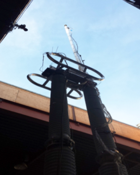
Porcelain insulators have long been an integral part of power systems due to their rigidity, which assures alignment of components in substation equipment. At the same time, there have been great advancements in understanding the seismic events that impact such insulators at substations.
Resonant frequencies from these events can cause immense dynamic forces and, due to its weight and brittle nature, porcelain is more susceptible to destructive harmonic frequencies. But with good design practice, advanced materials and modern manufacturing methods, porcelain insulators can still prove a dependable form of insulation in seismic service environments.
Material characteristics play a major role in equipment design under such dynamic forces and, while steel and aluminum are ductile and offer predictable strength, porcelain is non-ductile and can vary greatly in strength. Seismic performance of porcelain insulators can therefore be enhanced through maximizing strength and reducing weight.
It is also better understood these days that the insulator is but one component in a complex array that makes up any device found in a substation. Therefore, the entire device needs to be evaluated. For example, insulators are often mounted on concrete or steel structures and support the actual equipment while bushings are typically found at the top of equipment. The response of equipment and its sub-components to input frequencies will therefore depend on these and other factors.
This edited past contribution to INMR by Patrick T. Maloney at PPC Insulators explained the forces resulting from seismic activity with specific reference to porcelain insulators and proposed how performance can be optimized for such risk.

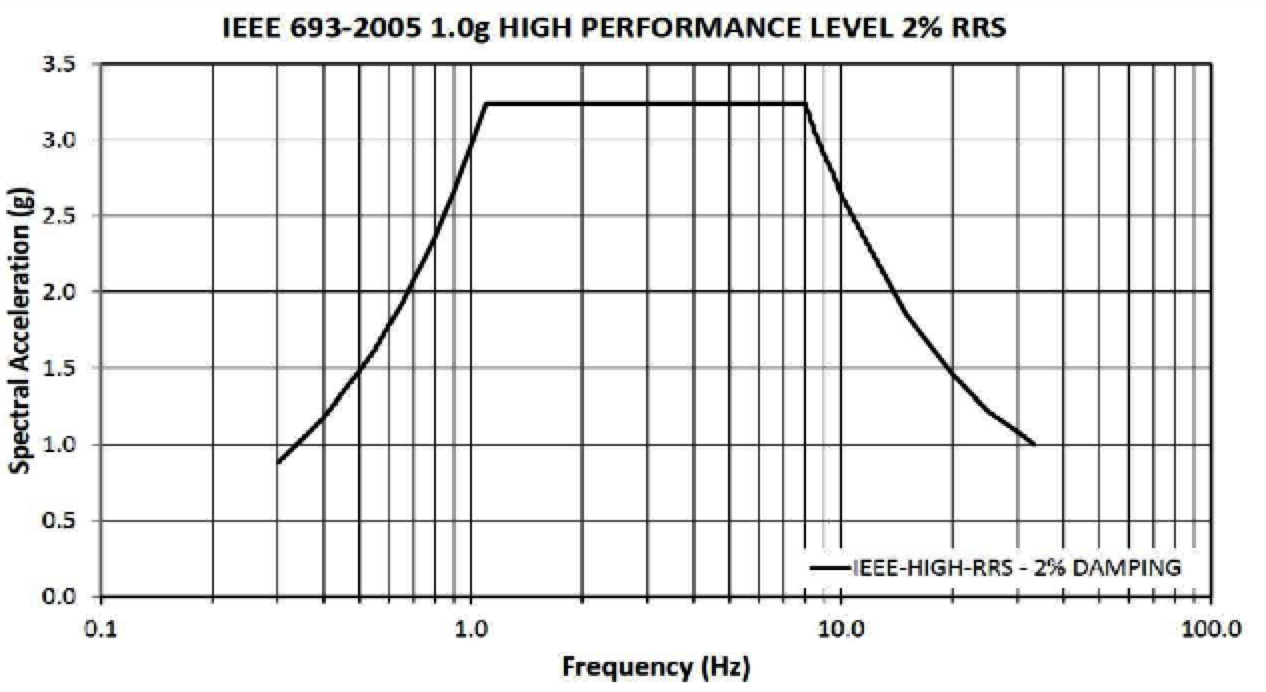
When the natural frequency of a piece of equipment closely matches input frequency, resonance occurs thus amplifying resulting dynamic motion and acceleration response. The Required Response Spectrum (RRS) simulates amplitudes, frequencies and energy in typical seismic events. Equipment having 1.1 to 8 Hz natural frequencies is most closely covered in the RRS.
Typical types of high voltage equipment have several characteristics that make them more responsive to seismic inputs. Being tall and heavy, they exhibit lower levels of Natural Frequency normally found in seismic events. When two items vibrate at the same natural frequency, increased motion is seen and induces great cantilever loads. Understanding the forces to which an insulator is being subjected in comparison with the strengths and weakness of its ceramic material is an important first step. Insulator mechanical ratings include: a. Cantilever/Bending moments; b. Torsion; c. Tension; and d. Compression. Cantilever loads determine core diameter and thus weight.
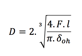 where: D – core diameter; F – required strength (min. breakage load); l – length; δoh– specific strength of porcelain.

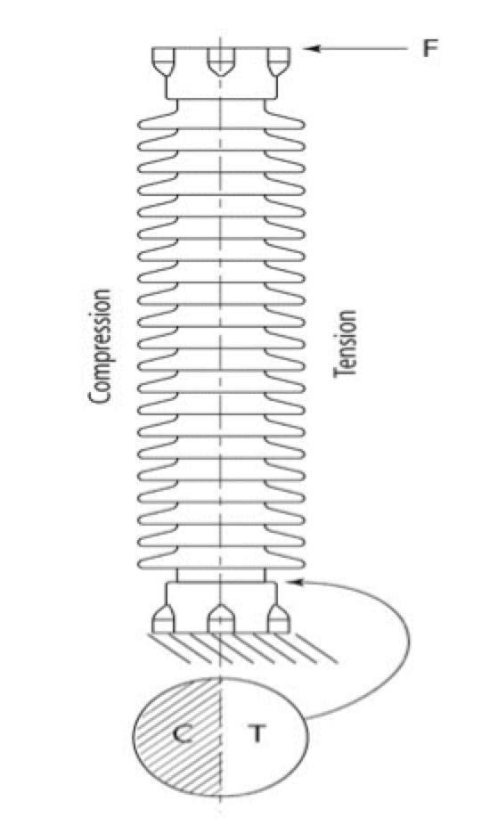
Ceramic materials have high compression ratings and low tension ratings. Bending moments induce compression and tension stress and tensile stress is amplified by the lever action of insulator height (as in Fig. 1).
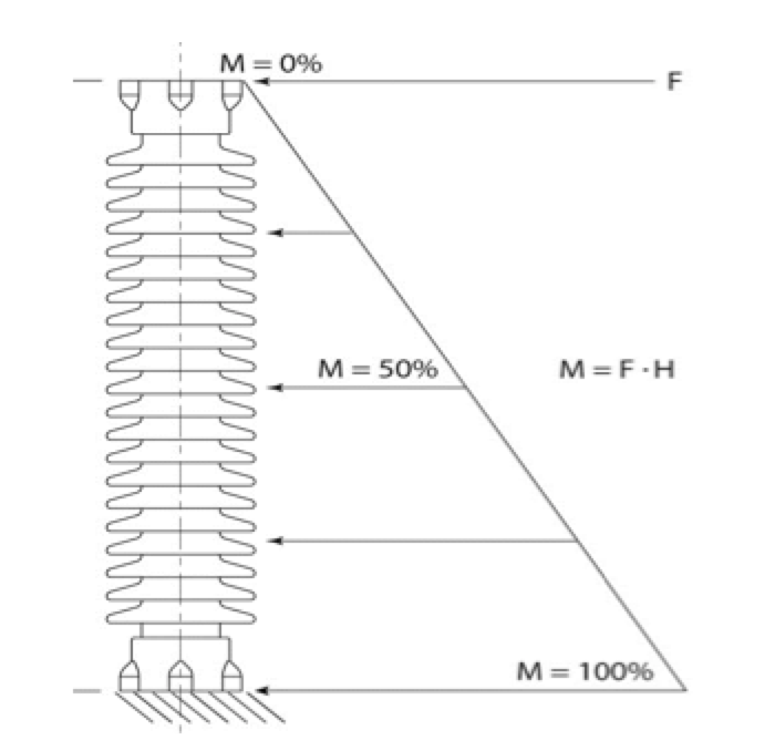
Bending moments increase with greater force and/or taller insulators (as per Fig. 2). In the case of dynamic motion, force is based on: 1. insulator mass and mass mounted above the insulator; and 2. acceleration due to the seismic event.
Trying to make design changes to ensure a piece of equipment’s natural frequency remains outside a seismic event’s frequency is often not possible. Since weight is a key factor when calculating the force/energy that goes into the equipment during a seismic event, the challenge is optimize design and maximize strength to weight ratio.
Weight Reduction
There exist ways to reduce the weight of a porcelain insulator of given strength. First of all, insulators should ideally be specially designed for the need. Moreover, maximizing section lengths helps reduce weight on multi-stack insulators. Manufacturers also have material choices that offer higher strength and maintaining tight quality assurance standards can further enhance overall strength.

Optimizing Design
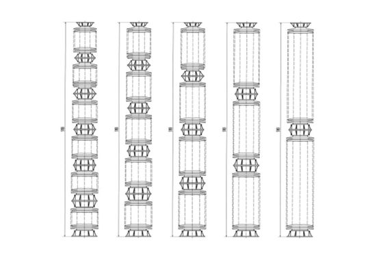
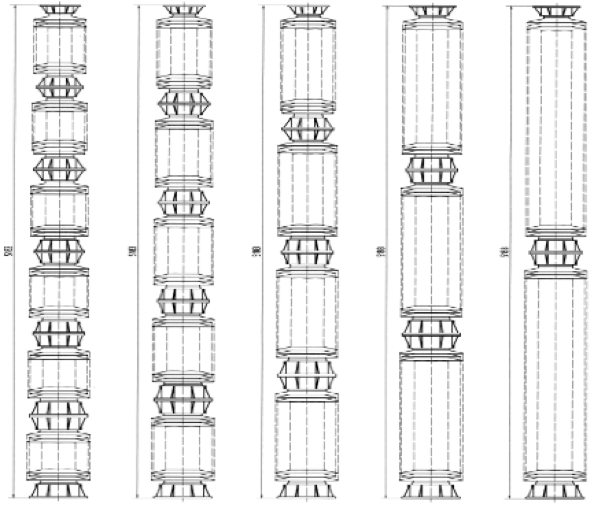
The design of an insulator needs to account for its application under seismic conditions. Often, insulators used at substations are based on standard designs intended to perform across a range of applications. An example is an insulator with uniform cylindrical cores that can be applied upright but is considerably heavier when under-hung. While tapered insulators are increasingly used in HV applications, determining optimal taper is important.
When any piece of equipment is considered for application under seismic conditions, the entire assembled and mounted structure must be evaluated using applicable software. Finite Element Analysis (FEA), for example, will identify high stress areas in any given configuration. Low stress zones will be identified as well. The equipment designer/consultant should also work closely with the insulator manufacturer to ensure all zones have equal safety margin. In fact, it can take several iterations to fully identify all optimum increases and decreases in strength at given locations along the insulator. Whenever lower stress areas are identified and remedied, weight in that region can be reduced and weight reductions in top sections can reduce strength needed in lower sections. This process results in less mass, less motion caused by the mass and less overall stress. Cost of shaker table testing is very costly for large substation equipment. A thorough evaluation by a competent seismic specialist can control such costs by avoiding the need to re-test. The location of an insulator in any piece of equipment is fundamentally important as well. In many cases, insulators support heavy pieces of equipment. If equipment is made more compact in terms of mass near the top, very little bending stress will be placed on the top fitting. Such analysis could confirm that a highly tapered insulator would be most appropriate for the application (see Fig. 3).
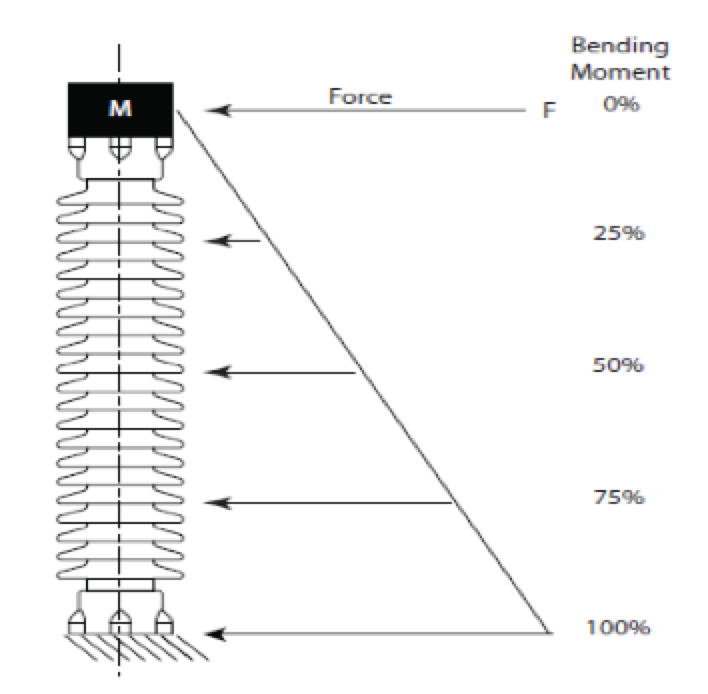

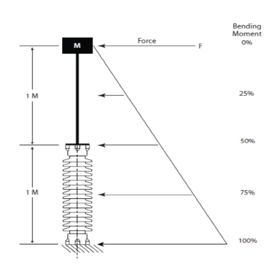
If equipment has a high center of gravity with the mass positioned well above the insulator, the top fitting will be subject to much greater bending stress and a more robust design for this top portion will be necessary. As illustrated in Fig. 4, for example, the top of the insulator is subjected to 50% of the maximum bending load.
Mass at the top of the insulator has the greatest bending effect. For example, in the case of an air break switch in the open position with mast fully extended there are high bending moments at the top of the insulator (see Fig. 5).
A typical 500 kV air break switch is mounted 4.6 m up on a structure and in the open position the switch can be 9.75, i.e. a total distance of 14.35 m from ground level to top of mast. Optimizing the strength needed at the top of an insulator can prove a critical material reduction zone since weight reduction is where the mass is furthest from the bending moment.
Shed Weight
Shed profile is a means to increase creepage distance, yet sheds contribute weight to an insulator. In the past, sheds have typically been up to 19 mm at the core tapering down to 12 mm at the tip. With improved material science, shed size can be reduced, resulting in a 20% reduction in shed weight.
Reduced Sections
Insulators are comprised of single or multiple sections bolted together. Insulators are typically single piece construction up to 750 kV BIL. High voltage insulators can be made up of many sections depending on the voltage level. Stress concentrations are found at the joints where the cast iron fittings are cemented onto the porcelain. The diameter of the porcelain at the fitting is increased due to the concentrated stress levels. Reducing number of sections will reduce high stress locations as well as the weight of the additional fittings (see Fig. 7).
Material
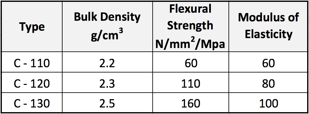
Porcelain insulators are technical ceramics containing a mix of kaolin, alumina, feldspar and silica (quartz). IEC 60672-3 refers to three main types: C-110, C-120 and C-130. C-110 is known as quartz porcelain while C-120 and C-130 are alumina porcelains. C-120 contains 20%-30% alumina whereas C-130 normally has alumina content greater than 30%. Increased in strength translates into the highest strength to weight ratio. The strength values shown in Table 1 are minimums and can be greatly exceeded. Insulators manufactured with C-130 clay with higher than minimum levels can offer up to 40% reduction in weight.

Production Process
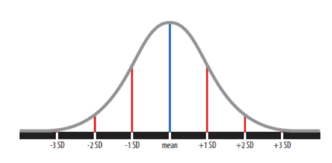
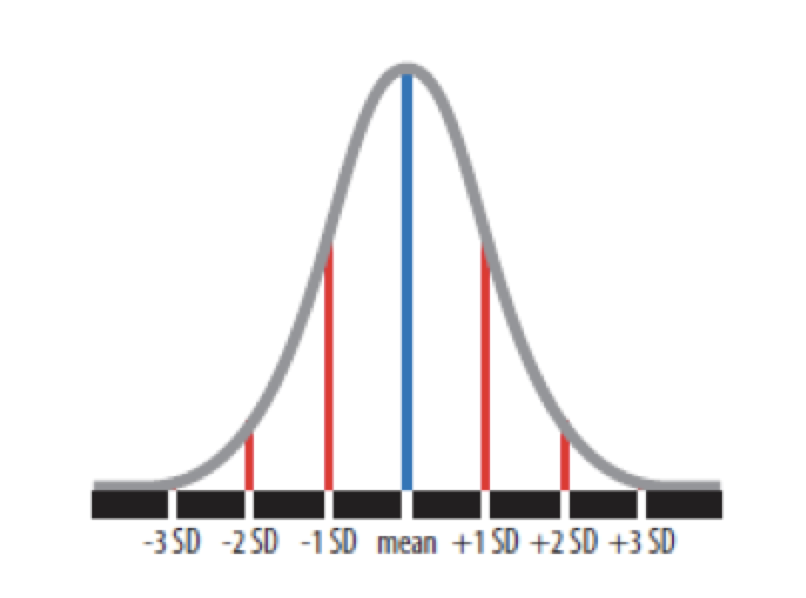
Manufacture of clay materials has an inherently wide range of resulting material strengths. Such variation can occur within a batch or between batches. Achieving consistent body strength is difficult, especially if processes are not tightly controlled. Indeed, it has been demonstrated that strength of ceramic materials can have over 35% standard deviation. The larger the deviation, the heavier the design of the insulator needed to ensure meeting the Specified Mechanical Load (SML). Reducing standard deviation directly reduces weight of any given manufacturer’s design parameters. For example, design of insulator with SML of 10 kN and std. dev. of 3.5 kN means that the design must be such that the average is 17 kN. On the other hand, if std. dev. is only 1 kN, design can be based on an average of 12 kN. This can result in about a 40% reduction in insulator weight (see Figs 8 and 9).
To better understand possible causes of variations in body strength, it is necessary to know more about how porcelain insulators are produced. Many are manufactured by the wet or plastic method, whereby clay recipes are measured and mixed with water to create the base material, called slip. A ball mill grinds the slip to ensure proper particle size and contains approximately 50% water. Slip is then filtered to remove natural contaminants found in clays, whether organic or iron. The slip is then pressed into filter cakes at about 22% moisture and these are chopped and extruded into blocks. Finally, cylindrical blanks or pugs are extruded. Over a 5 to 6 week period, the blank is turned and dried to less than 1% moisture content. To maintain consistent body strength, all these steps leading to the finished product must also be managed consistently. Particle size, chemical composition, water content of filter cakes, hardness of blanks and drying techniques will all determine predictability of body strength. The multiple drying steps of the wet clay – from pressing of filter cakes to use of dryers that prepare turned insulators for firing – are key production steps for porcelain insulators, with perhaps the most critical in drying being taking the wet turned shape from 18% moisture content to less than 1%. This is because the thin sheds and thick core need to dry at the same rate, even though relatively thin sheds are far more likely to give off water. Up to 6 weeks can be required to slowly dry an insulator and many manufacturers have proper controls in place to assure this. Still skilled employees and constant attention to detail are necessary.
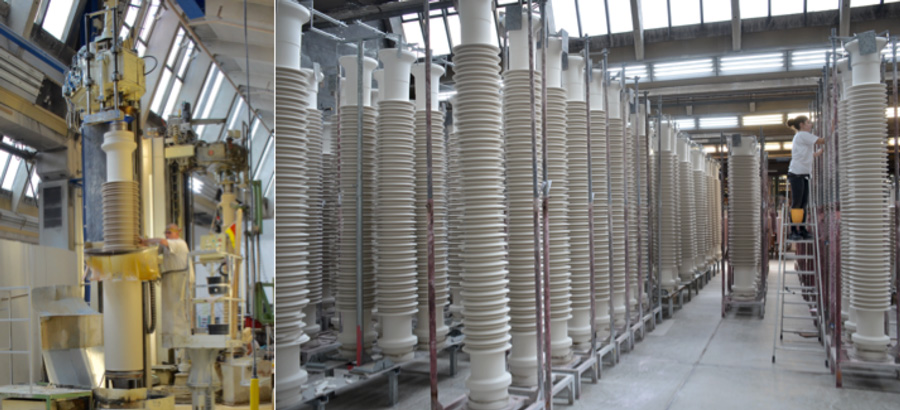
An alternative manufacturing method for porcelain insulators has been developed and eliminates many steps in the drying process discussed above. An important benefit offered is a far more consistent process that helps reduce risk of possible variation in material strength. This method, called isostatic, begins with drying the slip to a fine powder, which is then pressed under great force into a dry cylinder. The inherent advantage is being able to produce dry cylindrical blanks in a relatively short time. In fact, insulators produced using the isostatic method have a production time of less than two weeks versus 6 or more weeks required for wet/plastic production. Moreover, turning is performed dry. This eliminates shrinkage from wet turned profiles to dried/ready for firing state and results in tighter tolerances. Dry pressed blanks have no particular grain orientation, as found in wet extruded blanks. Since a wet body is extruded through the extruder throat, clay flow can be much slower along the walls due to friction between clay and extruder wall. Internal to the blank, shear will occur causing internal stress, which can lead to failures in the kiln and reduce mechanical strength. Depending where in the blank the insulator comes from, these shear areas can end up near the surface. One notable trait is the camber that forms as a porcelain insulator is being dried.
Conclusions
Improving the performance of porcelain insulators under seismic service conditions is possible mainly through weight reduction methods. Optimizing design based on specific actual application using high strength materials as well as maintaining a consistent manufacturing process will ensure the best performance possible.