The advantages of braced line post (BLP) assemblies have led to their rising use in transmission line design. Moreover, as line designers push for greater efficiency, these assemblies are seeing application at increasing voltages as well as with higher mechanical ratings. However, present standards do not yet well define proper test techniques to determine their electrical and mechanical ratings. Moreover, the complexity of such assemblies, which combine a post insulator and a braced suspension insulator, makes it a challenge to properly test and rate them. As such, more work is needed to drive standardization. It is also important that present non-standardized test methods be well understood by end users so that they can better consider the impact these might have on results as well as on BLP assembly ratings.
This edited past contribution to INMR by Jeff Butler, Principal Engineer, Transmission at Hubbell Power Systems reviewed this topic with focus on assemblies using composite/polymer designs and in configurations where the suspension insulator is not in a fully vertical orientation, i.e. with an interior angle between suspension and post insulator of < 90°. Definitions consistent with “IEEE Guide for Braced Assemblies for Overhead Transmission Insulator 60kV and Greater” also apply.
A strut or line post insulator is designed to withstand combined tension and compressive loads. Depending on material and base, this insulator can also withstand bending loads.
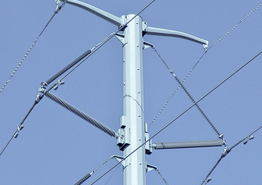
The strut insulator is typically mounted to a structure horizontally (e.g. typically ≤ 15° from horizontal) with various types of line end mounting attachments based on anticipated loading. To make up the rest of the braced insulator assembly, the line end of the line post (strut) insulator is restrained by a suspension insulator which is also attached to the structure at a defined distance above the strut, thus forming an interior angle between insulators.
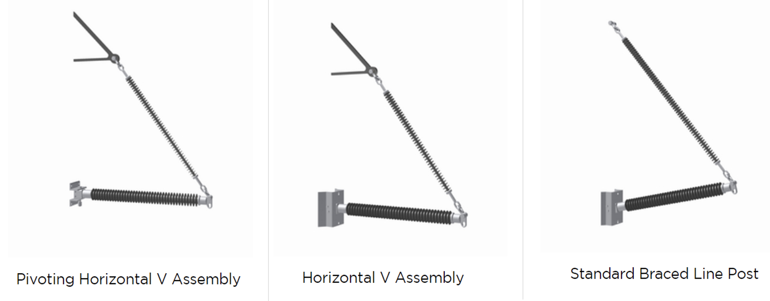
Braced insulator assemblies are generally categorized into two types:
(1) assemblies with the line post (strut) insulator rigidly attached to the support structure and therefore unable to rotate about the attachment point in response to unbalanced longitudinal conductor loads; and
(2) assemblies where the line post insulator is attached in a non-rigid manner to the support structure by means of an articulated fitting that can provide rotation about the attachment point.
Common terms for assemblies of the first type are ‘braced posts’ or ‘rigid/fixed base horizontal vees’. Assemblies of the second type can also be referred to as a “pivoting horizontal vee”. In this discussion, the general term for both assemblies with be a Braced Line Post or “BLP” and further distinction between the two types will be noted as necessary.
How Standards Apply to Braced Line Post Assemblies
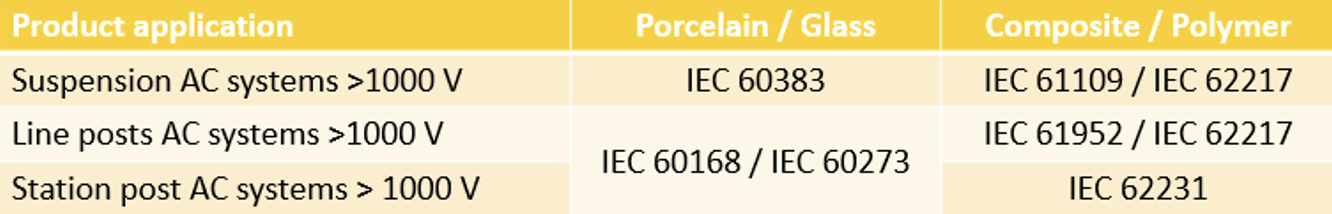
Standards have evolved in response to new technologies and applications. For example, Table 1 lists some IEC standards relevant to insulators made of both ceramic and composite materials. These standards are applicable worldwide and include test procedures related to electrical and mechanical ratings of the referenced insulators. These standards also include the specific criteria for evaluating results of the test methods prescribed.
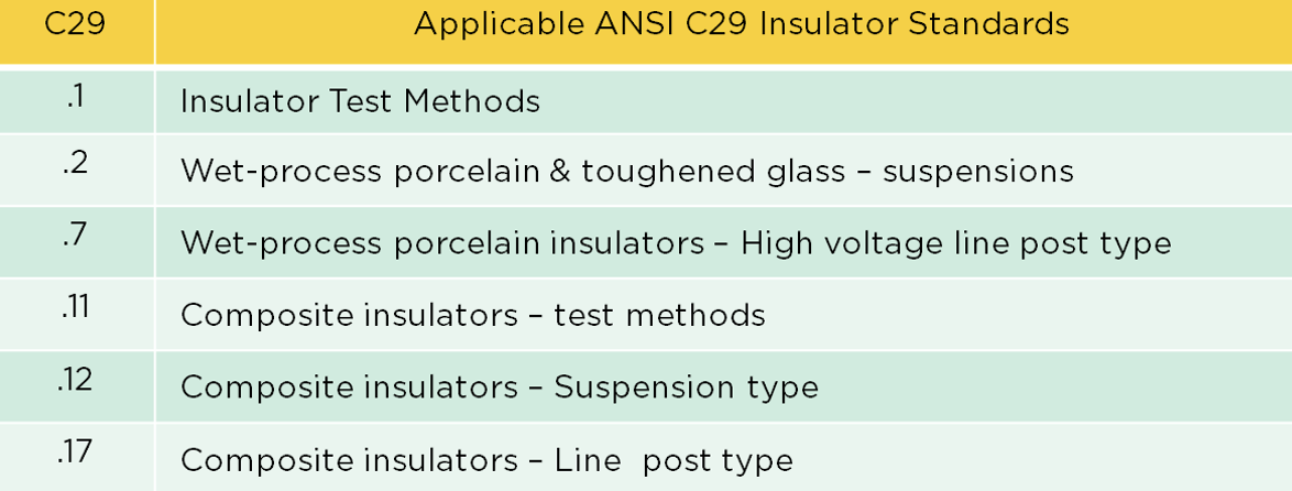
Similarly, standard setting bodies such as ANSI have included relevant testing and criteria in their C29 standards (see Table 2). These test methods also include reference to electrical and mechanical ratings for the insulators.
Both international and country-based standards attempt to address different aspects of insulators that are important to define and standardize. Indeed, such standardization of testing has allowed consistency and reliability of insulators from different manufacturers who may employ different production processes and materials. In fact, one of the primary goals of standards has been to allow interchangeability of related products. However, these standards currently only address high voltage insulators in their individual application, whether as a suspension or as line post. There are presently no directly relevant IEC or ANSI standards relating to the combination of both into a braced line post assembly. As such, the standards do not factor in the important effects that can arise when combining these two types of insulators.

How Standards Apply to BLP Assemblies: Electrical Ratings
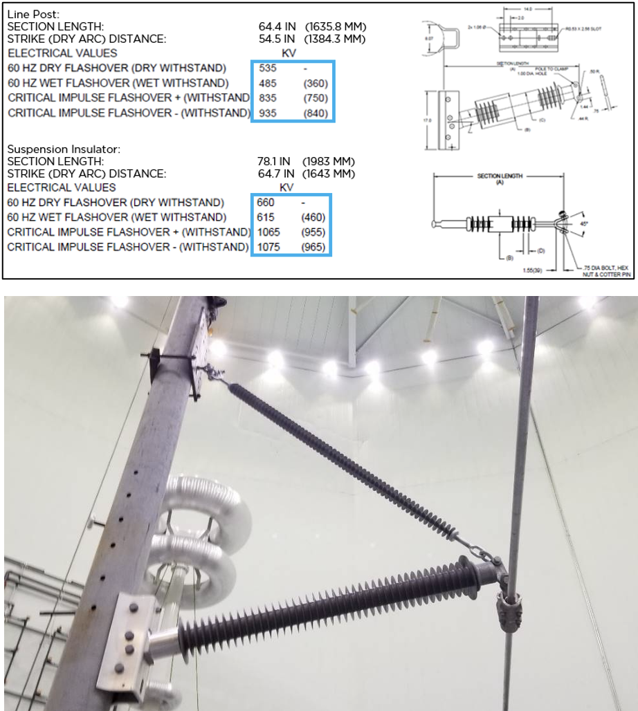
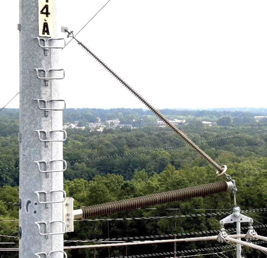
(bottom) Braced line post assembly for electrical testing.
Standards provide guidance on determining electrical ratings of individual insulators. In ANSI standards, for example, low-frequency flashover values are determined by the arithmetic mean of at least 5 flashover values determined through HV testing on the insulator (per ANSI C29.1 and C29.11). Similarly, IEC 60383-1 and IEC 60383-2 present the critical impulse flashover (CIFO) voltage as determined by 50% flashover of the insulator during HV testing.
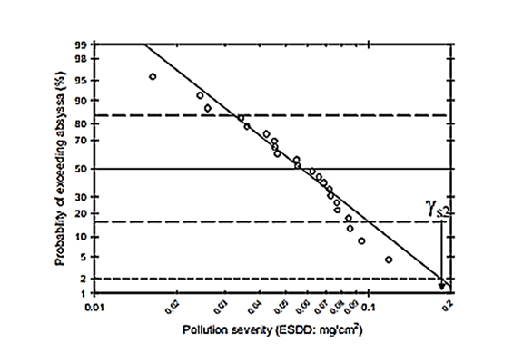
Looking at both standards applied to a braced line post assembly, it could be inferred that a suitable test method would include a 50% flashover voltage for each insulator in the assembly or a 75% probability of a low flashover value for an assembly that combines the two separate insulators.
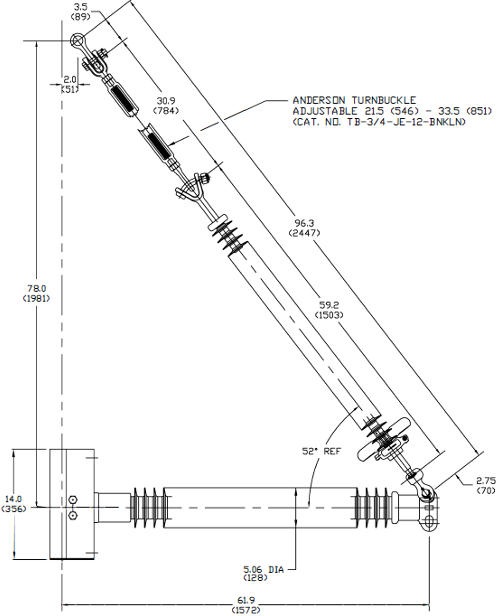
Evaluation of precisely such a test method was carried out on a braced line post assembly (shown in Fig. 4) to evaluate its electrical performance. The test assembly consisted of two insulators of unequal length, with the suspension insulator having a greater dry arc distance than the line post. The test method was as prescribed per ANSI C29.1 for low frequency flashover and impulse flashover values. However, once the test was completed, this procedure also included observing which insulator experienced the flashover since the effective dry arc distance of the longer suspension insulator was reduced.
The assembly was first evaluated to determine Critical Impulse Flashover (CIFO) voltage. As the assembly was being repeatedly tested, flashover voltage was recorded as was the count of flashovers for each insulator relative to the dry arc distance of the suspension insulator (see Fig. 5). Count of flashovers was plotted on the right-side axis and flashover voltage on the left axis. Results were captured as the length of dry arc distance of the suspension insulator was reduced. The count of all flashovers occurred across the line post until the suspension insulator began to approach a matching dry arc distance.
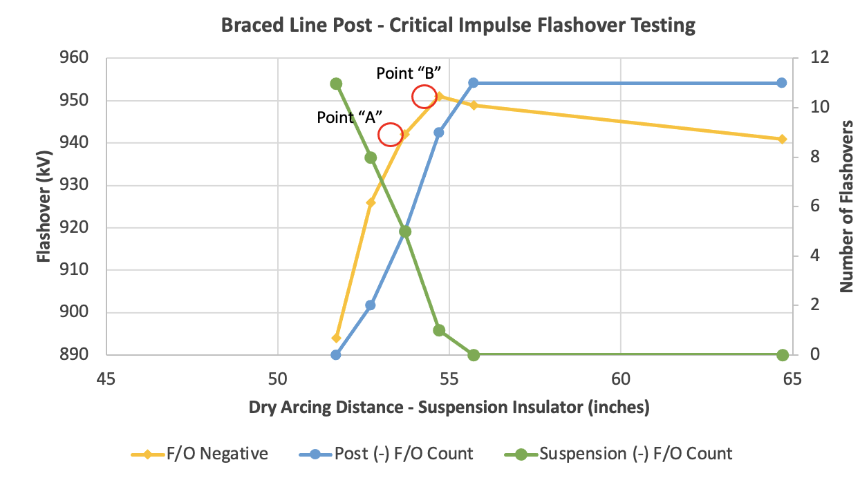
As this occurred, flashovers began to manifest across the suspension until an equal number occurred across both insulators at a suspension insulator dry arc distance of 53.7” and a value of 942 kV (see Point “A” in Fig. 5). However, prior to achieving equal numbers of flashovers across both insulators, the highest flashover voltage for the assembly was observed at 951 kV, when suspension dry arc distance was 52.7”.
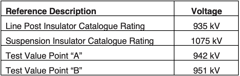

Results of this testing did not follow the expectation that flashover voltage demonstrated values lower than the rating of either insulator (see Fig. 3) as might have been expected given the probabilistic approach in the standards discussed above. However, based on the ratings of both insulators and the findings from testing, the lack of clarity in the standards clearly presents a challenge in how to properly determine the rating of the assembly (see Table 3).
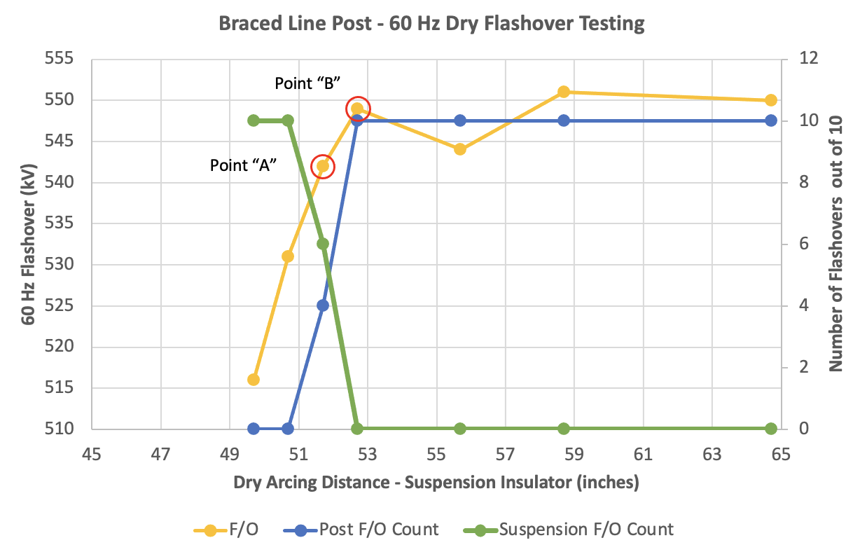
Similar testing was performed on the same assembly following a similar process to evaluate its dry flashover voltage performance. Count of flashovers was plotted on the right-side axis and flashover voltage recorded on the left axis. Results were captured as the length of the dry arc distance of the suspension insulator was reduced. The count of all flashovers occurred across the line post until the suspension insulator began to approach a matching dry arc distance. As this occurred, a number of flashovers began to manifest across the suspension insulator until an equal number occurred across both insulators at a suspension insulator dry arc distance of 51.7” and at 542 kV (Point “A” in Fig. 6). However, prior to achieving equal numbers of flashovers across both insulators, the highest flashover voltage for the assembly was observed at 549 kV with a suspension insulator dry arc distance of 52.7”.
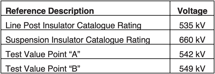
As with the earlier CIFO results, dry flashover test results also did not follow the expectation that flashover voltage demonstrated values lower than the rating of either insulator (see Fig. 4). This would have been expected given the probabilistic approach from the standards discussed above. However, based on the ratings of both insulators and the test findings, lack of clarity in the standards again presents a challenge in how to properly determine the rating of the assembly (see Table 4).

As demonstrated by the above testing, there is strong correlation between the dry arc distance of either insulator and the flashover values of the assembly. Further exploration of this interaction was explored with additional electrical testing of a similar BLP assembly. In these tests, the insulators remained the same (see Fig. 7) but the dry arc distance was impacted by using corona rings.
The assembly was tested for Critical Impulse Flashover (CIFO) values, as defined per ANSI. Insulators and assemblies were evaluated with and without corona rings as well as slightly modified hardware that provided adjustment to effective dry arc distance of the assembly (see Table 5). Results now showed the impact of corona rings and other hardware on the dry arc distance as well as on the associated electrical rating of the assembly. However, as previously discussed, even with these values, it remained unclear what the electrical rating of the assembly should be.
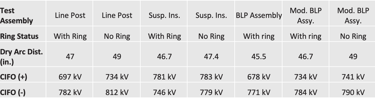
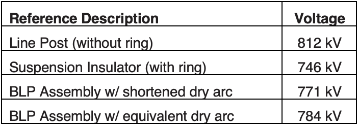
As per the standards, there is little guidance to determine an appropriate rating from the various ratings and test results. To maintain some consistency with previously reviewed results, the CIFO negative value was compared. The BLP assembly was tested with the combination of the line post and suspension insulator with a corona ring (see Fig. 7). However, this resulted in a shorter effective dry arc distance for the assembly than either insulator individually (see Table 5). Further, the assembly was modified with hardware that would allow for the effective dry arc distance of the assembly to match that of the shorter of the two individual insulators, i.e. an equivalent dry arc distance of 46.7” to match the dry arc distance of the suspension insulator. Test results did not indicate any reduction in demonstrated flashover value for the combination of the two insulators, as discussed with the probabilistic approach presented in ANSI and IEC standards.
Evaluation of the electrical characteristics of BLP assemblies, as discussed above, confirm that special consideration must be made to properly determine the electrical ratings of these assemblies. Based on the nature of assembly and the combination of two insulators that are electrically parallel, the standards currently do not offer enough guidance to define proper testing procedures and thus appropriate electrical ratings.

How Standards Apply to BLP Assemblies: Mechanical Ratings
Evaluation of the standards for guidance related to mechanical ratings for BLP assemblies also uncovers comparatively little. In relation to mechanical testing and determination of mechanical rating, there is no directly applicable guidance for the combination of a line post and a suspension insulator. While standards do provide test methods for the individual insulators, this is not appropriate for the assembly since it does not properly address the dramatic impact of combining both insulators compared to the mechanical strength of the individual insulators. This lack of direct guidance proves to be problematic as manufacturers and end users attempt to define the mechanical ratings and applicable test methods for these important assemblies. Moreover, the current lack of defined standards results in variation of these test methods based on factors defined by the manufacturer, the test facility or the end user. Increased consideration of applying braced line post assemblies at higher voltages and in more critical applications further magnifies the need for standardized guidance for mechanical testing and rating of BLPs.
A variety of different test methods are utilized across the industry that relate to establishing the mechanical ratings of BLP assemblies. However, findings of these various methods can show significant differences based on different arrangement of the testing and application of test load. Given such variability across test methods, mechanical testing was performed using the same assembly but with three different test methods that have three different applied loads.
1. Free-Weight Method: Load is applied as added weight to a sled that is suspended from the line end of the assembly.
2. Fixed Point Loading: Load is applied from a fixed point to the line end of the assembly.
3. Field Simulation Method: Load is applied as a combination of suspended weight from the line end fitting as well as from simulated spans connected to both sides of the assembly, i.e. to simulate adjacent spans.
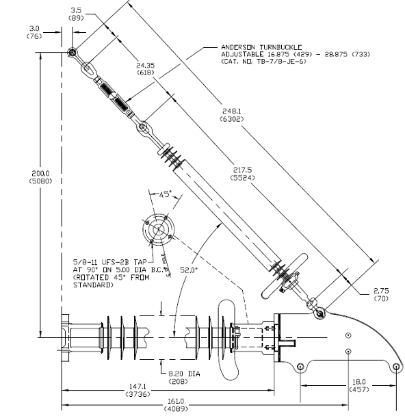
The assembly design for this comparison of mechanical testing consisted of a combination of a line post and a suspension insulator (see Fig. 8). The line post had a rod diameter of 3.5” and section length of 161” (4089 mm). The suspension insulator was rated at 50k lbs. with a 7/8” (22 mm) rod diameter and a section length of 217.5”. This was a horizontal vee assembly where the line post is in a horizontal position with a fixed attachment of the ground end to the tower. Overall length of the support string was 248.1” (6302 mm) that included the suspension insulator, a turnbuckle and necessary connecting hardware.
The assembly was tested using the three different load methods presented above and deflection of the line end of the assembly was measured for comparison.

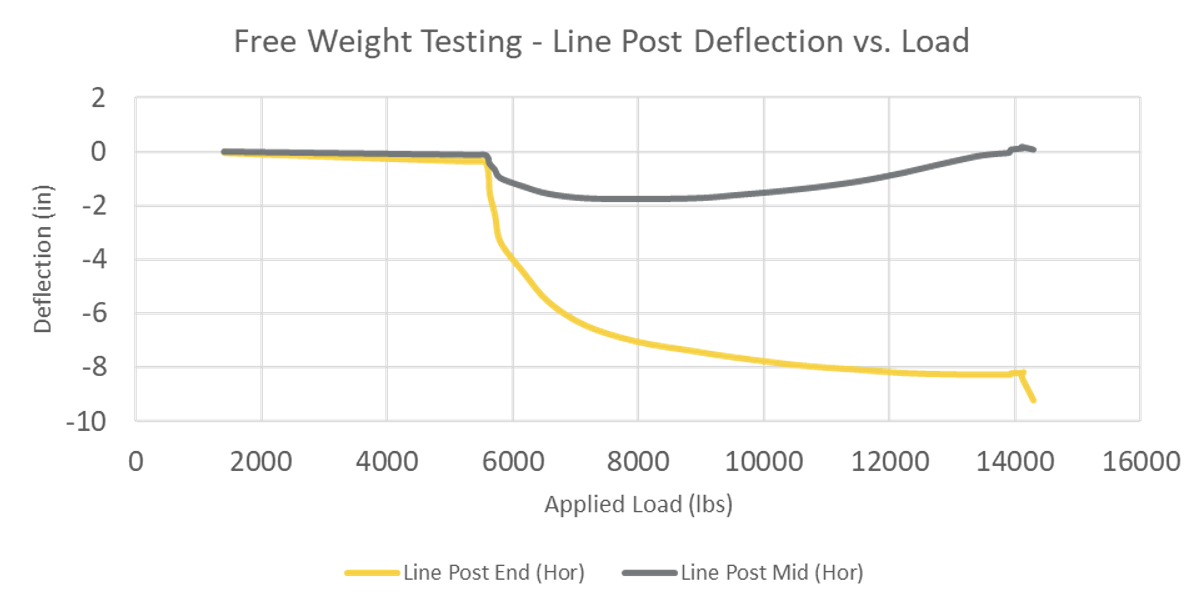
1. Free Weight Method: Test Results
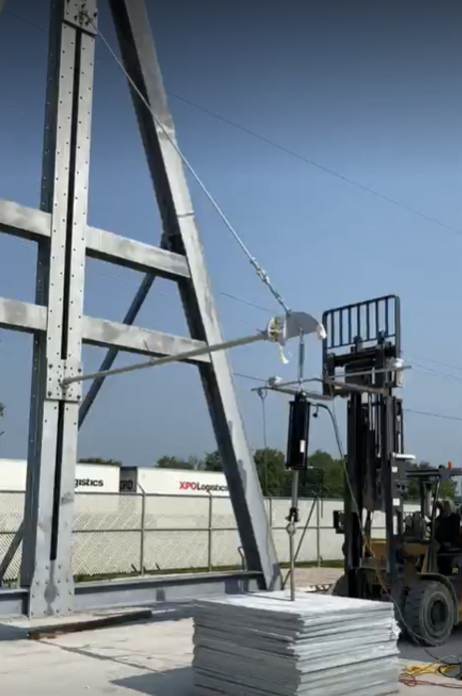
A hydraulic cylinder was attached to the line end fitting of the assembly while the other end was attached to a sled on the ground (see Fig. 9). Incremental weight was added to this sled and load applied to the assembly. The sled was allowed to move freely as the cylinder retracted and the sled was lifted from the ground. As the name of this test method suggests, this allowed for movement of the free weight as the load was applied. Deflection was recorded in the horizontal plane at both the mid-point of the line post insulator and the line end fitting of the assembly (see Fig. 10). Deflection was recorded up to a load of ~14,000 lbs. (~6300 kg).
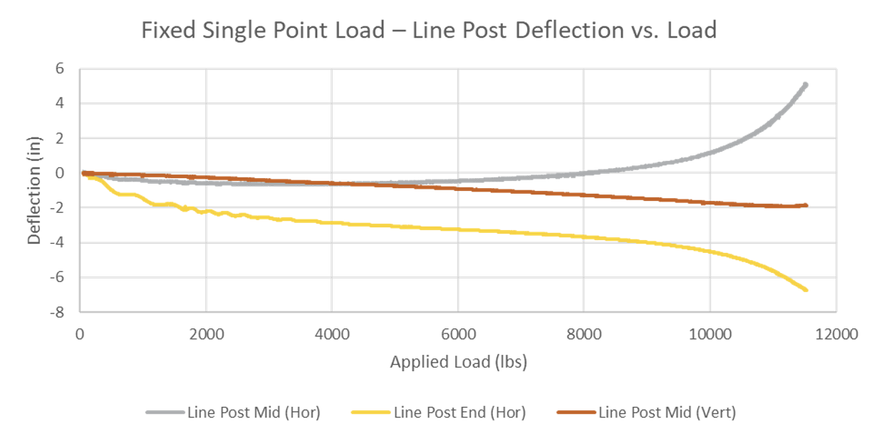
2. Fixed Point Method: Test Results
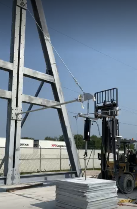
Initial set-up was similar to the Free Weight Method but in this case the hydraulic cylinder was connected to a sled that served as a fixed point as load was applied to the assembly (see Fig. 11). The sled was loaded with a stack of weights that exceeded the mechanical strength of the assembly and would not move during testing. The name of this test method is based on the fixed-point anchoring of the applied load during testing. Deflection was measured in the horizontal plane at both the mid-point of the line post insulator and the line end fitting of the assembly as was the vertical deflection of the mid-point of the assembly (see Fig. 12). This deflection was recorded up to a load of under 12,000 lbs. (~5400 kg).

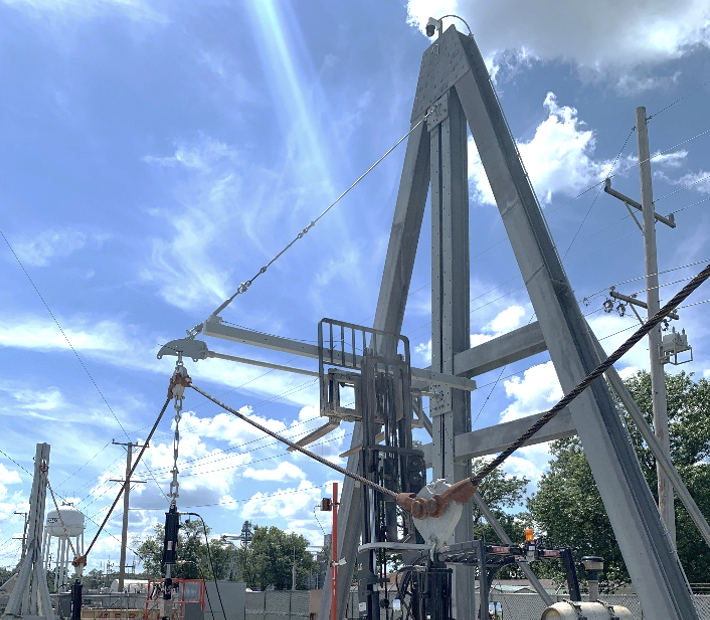
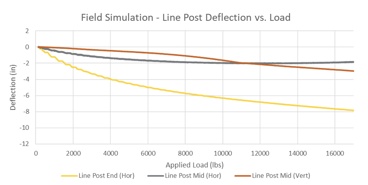
3. Field Simulation Method: Test Results
In this test set-up, the load was applied as a combination of suspended weight from the line end fitting (similar to the free weight method) as well as load applied to hardware connected to both sides of the assembly to simulate adjacent spans. The name of this test method is based on including the effects of the connecting hardware spans more closely, representing a field simulation arrangement. Cumulative load was measured at the line end fitting (see Fig. 13). Deflection was measured in the horizontal plane at both the mid-point of the line post insulator and the line end fitting of the assembly as was vertical deflection of the mid-point of the assembly (see Fig. 14).
Discussion of Test Results
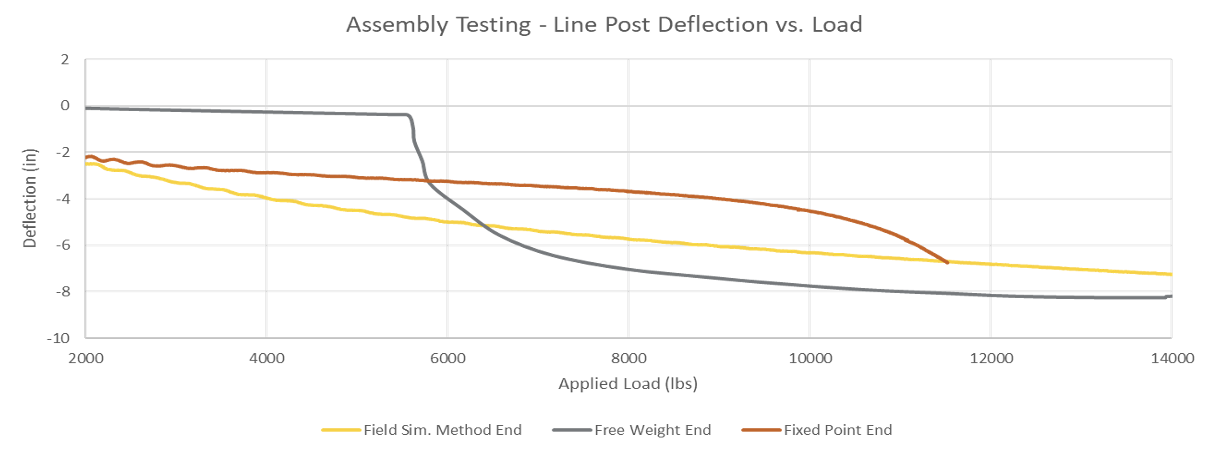
The results of all three methods were compared and horizontal deflection of the line end of the assembly was plotted (see Fig. 15). Evaluation of deflection serves as a straightforward methodology to evaluate behavior of an assembly based on test method and applied load.
In this comparison, for example, the findings demonstrate that different test methods can result in different deflection of the line end of the braced line post assembly. This variation in deflection values confirms that different forces are being experienced by the assembly for the given applied load. However, defined mechanical rating for this assembly would be influenced differently, depending on test method and applied load. Such differences could significant impact how this assembly should be rated for mechanical ability.
Conclusions
Braced line post assemblies are being utilized worldwide in increasing numbers and at increasing voltages. Such growing acceptance only drives the importance of proper understanding and application of braced line post assemblies, especially on critical transmission lines. However, current standards do not yet provide sufficient guidance relative to suitable test procedures for these compound assemblies.
The complexity of these assemblies, which combine line post and suspension insulators, creates additional challenges when it comes to how best to test and rate them based on existing standards. Continued industry effort will be needed to drive toward acceptable standardization for all important aspects of these assemblies. The above discussion and examples provide information and test results that only confirm the challenges of properly testing and rating braced line post assemblies.
1 Reference: A. C. Baker et al., “IEEE Guide for Braced Insulator Assemblies for Overhead Transmission Lines 60 kV and Greater,” in IEEE Transactions on Power Delivery, vol. 23, no. 2, pp. 785-791, April 2008, doi: 10.1109/TPWRD.2007.909103.